ECU ASTON MARTIN DB7 1997 Repair Manual
[x] Cancel search | Manufacturer: ASTON MARTIN, Model Year: 1997, Model line: DB7, Model: ASTON MARTIN DB7 1997Pages: 421, PDF Size: 9.31 MB
Page 285 of 421
Air Conditioning
Working Practices O" 15-^?
Working Practices
General
Be aware of, and comply
with,
all health and safety
requirements.
Before beginning any repair or service procedure,
disconnect the vehicle battery ground connection
and protect the vehicle from dirt or damage.
Work in a well ventilated, clean and tidy area.
Recovery and chargeequipment must comply
with,
or exceed the standard detailed in the General
Description.
Handling Refrigerant
Wear eye protection at all times.
Use gloves, keep skin that may come into contact
with refrigerant covered. If the refrigerant comes
into contactwith youreyesorskin wash the affected
area immediatelyw'ith cool water and seek medical
advice, do not attempt to treat yourself.
Avoid inhaling refrigerant vapour, it wil
your respiratory system.
irritate
Never use high pressure compressed air to flush out
a system. Under certain circumstances a
combination of HFC 134A and compressed air in
the presenceofa source ofcombustion (for instance,
welding or brazing equipment), results in an
explosion that releases toxic compounds into the
atmosphere.
The refrigerant and CFC 12 must never come into
contact with each other
as
they form an inseparable
mixture that can only be disposed of by incineration.
Do not vent refrigerant directly into the atmosphere,
always use approved recovery equipment.
Refrigerant is costly but it can be recycled. Clean
the refrigerant, using the recovery equipment and
reuse it.
Carry out LeakTestsonly with an electronic analyser
dedicated to Refrigerant El 34A.
Do not attemptto guess the amount of refrigerant in
a system, always recover it and recharge with the
correct charge weight. Do not depress the charge or
discharge port valves to check for the presence of
refrigerant.
Handling Lubricating Oil
Avoid breathinglubricantmist,itwillcauseirritation
to your respiratory system.
Always decant fresh oil from a sealed container. Do
not leave oil exposed to the atmosphere for any
reason other than to fill or empty a system; PAG oil
is hygroscopic (it absorbs water) and iscontaminated
rapidly by atmospheric moisture.
Following the recovery cycle do not reuse the oil
when it has been separated from the refrigerant;
dispose of the oil safely.
System Maintenance
Do not leave the system open to the atmosphere. If
a unit or part of the system is left open for more than
five minutes, it is advisable to renew the receiver-
dryer. There is not a safe period in which work is to
be carried out. Always plug pipes and units
immediately after disconnection and only remove
plugs when re-connecting.
If replacement parts are supplied without transit
plugs and seals do not use the parts. Return them to
your supplier.
Diagnostic equipment for pressure, mass and
volumeshouidbecalibrated regularly and certified
by a third party organisation.
Use extreme care when handling and securing
aluminium fittings, always use a backing spanner
and take special care when handlingtheevaporator.
Use only the correct or recommended tools for the
job and apply the manufacturer's torque
specifications.
Keep the working area, all components and tools
clean.
8-8 May 1996
Page 287 of 421
Air Conditioning
Temperature Distribution System
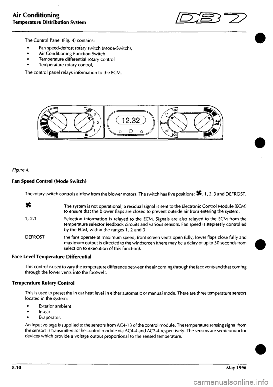
The Control Panel (Fig. 4) contains:
• Fan speed-defrost rotary switch (Mode-Switch),
• Air Conditioning Function Switch
• Temperature differential rotary control
• Temperature rotary control,
The control panel relays information to the ECM.
Figure 4.
Fan Speed Control (Mode Switch)
The rotary switch controls airflow from the blower motors. The switch has five positions: 3C, 1, 2,3 and DEFROST.
«» The system is not operational; a residual signal is sent to the Electronic Control Module (ECM)
to ensure that the blower flaps are closed to prevent outside air from entering the system.
1,
2,3 Selection information is relayed to the ECM. Signals are also relayed to the ECM from the
temperature selector feedback circuits and various sensors. Fan speed is steplessly controlled
by the ECM, within the ranges 1, 2 and 3.
DEFROST the fans operate at maximum speed, front screen vents open fully, lower flaps close fully and
maximum output is directed to the windscreen (there may be a delay of up to 30 seconds from
selection to execution of this function).
Face Level Temperature Differential
This control is used to vary the temperature difference between the air coming through the face vents and that coming
through the lower vents into the footwell.
Temperature Rotary Control
This is used to preset the in car heat level in either automatic or manual mode. There are three temperature sensors
located in the system:
• Exterior ambient
• In-car
• Evaporator.
An input voltage is supplied to the sensors from AC4-13 of the control module. The temperature sensing signal from
the sensors is transmitted to the control module via AC4-4 and AC2-4 respectively. The sensors are semiconductor
devices which provide a voltage output proportional to the sensed temperature.
8-10 May 1996
Page 289 of 421
Air Conditioning //~-->> ^/zz:^^ • ^ ^
General Svstem Procedures ' —"^ ^ '^ General System Procedures
From the condenser the liquid passes into the Receiver-Drier which has three functions:
• Storage vessel for varying system refrigerant demands.
• Filter to remove system contaminants.
• Moisture removal via the desiccant.
With the passage through the receiver-drier completed the, still high pressure liquid refrigerant, enters the Expansion
Valve where it is metered through a controlled orifice which has the effect of reducing the pressure and temperature.
The refrigerant, now in a cold atomised state, flows into the Evaporator and cools the air which is passing through
the matrix.
As heat is absorbed by the refrigerant it once again changes state, into a vapour, and returns to the compressor for
the cycle to be repeated (Fig. 5).
There is an automatic safety valve incorporated in the compressor which operates should the system pressure be
in excess of
41
bar. The valve re-seats when the pressure drops below 35 bar.
Note: The division of HIGH and LOW side is simply the
system pressure
differential created by the
compressor
discharge
(pressure),
suction
(inlet)
ports and
the
relative inlet and outlet
ports
of the
expansion
valve.
This
differential is critical to
system
fault
diagnosis
and efficiency checks.
System Protection
The trinary pressure switch, located in the liquid line, cuts electrical power to the compressor clutch if the system
pressure is outside of the range of 2 Bar
(1
st Function) to 27 Bar (2nd Function). The third function is to switch on
the cooling fans when pressure exceeds 20 bar.
General System Procedures
Leak Test
Faults associated with low refrigerant charge weight and low pressure may be caused by leakage. Leaks traced to
mechanical connections may be caused by torque relaxation or joint face contamination. Evidence of oil around
such areas is an indicator of leakage. When checking for non visible leaks use only a dedicated Refrigerant El 34A
electronic analyser and apply the probe all round the joint connection. Should a leak be traced to a joint, check that
the fixing is secured to the correct tightening torque before any other action is taken.
Do not forget to check the compressor shaft seal and evaporator.
Note: Never
use
a dedicated
CFC 12
or
naiced
flame type
analyser.
Charge Recovery (System Depressurisation)
The process of refrigerant recovery depends on the basic characteristics of your chosen recovery-recycle-recharge
equipment, therefore, follow the manufacturers instructions carefully. Remember that compressor oil may be drawn
out of the system by this process, take note of the quantity recovered so that it may be replaced.
CAUTION: Observe all relevant safety requirements.
• Do not vent refrigerant directly to atmosphere and always use approved recovery-recycle-recharge
equipment.
• Wear suitable eye and skin protection.
• Do not mix the refrigerant with CFC 12.
• Take note of the amount of recovered refrigerant, it indica
tes the
state of the
system
and
thus the
magnitude
of any problem.
8-12 May 1996
Page 313 of 421
Air Conditioning
Compressors ^?
Evaporator
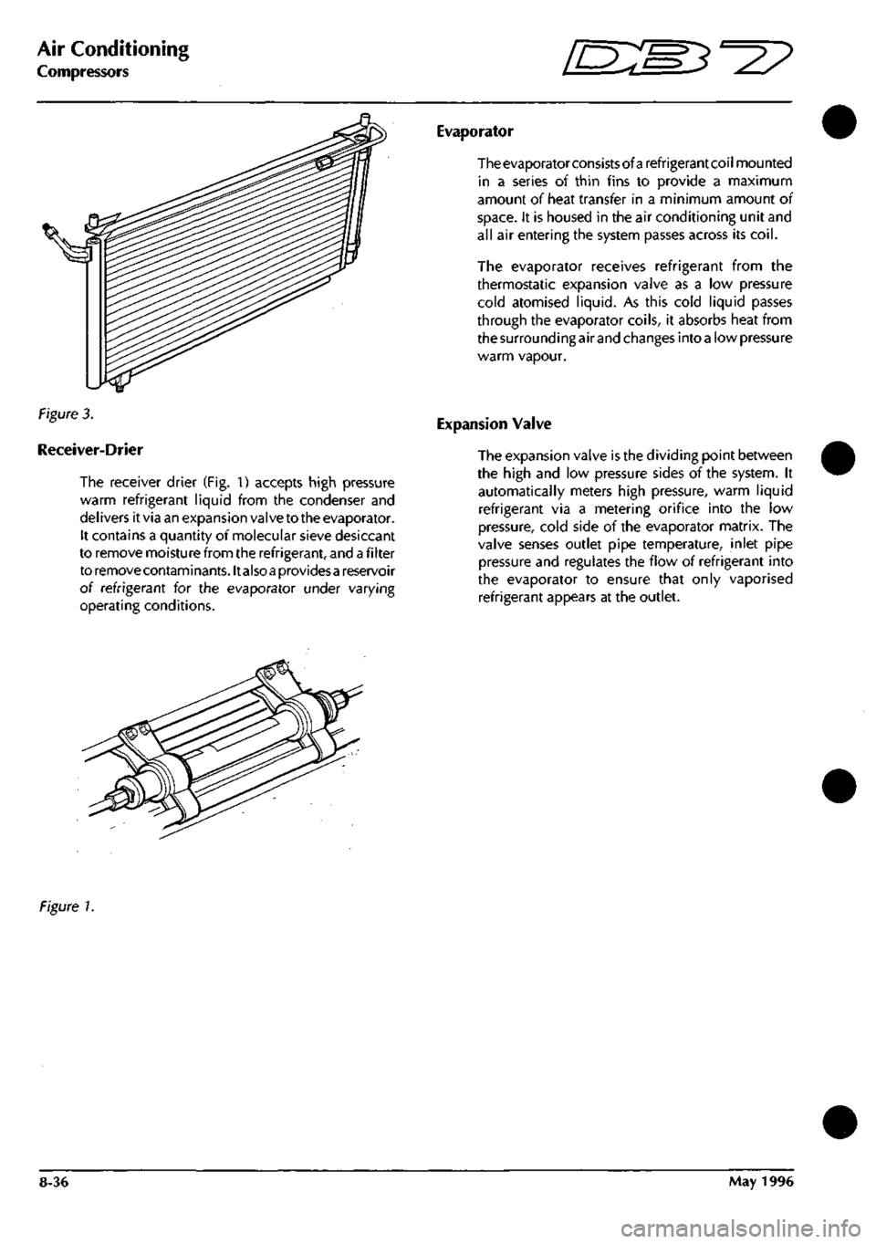
Figure 3.
Receiver-Drier
The receiver drier (Fig. 1) accepts high pressure
warm refrigerant liquid from the condenser and
del ivers it via an expansion valve to the evaporator.
It contains a quantity of molecular sieve desiccant
to remove moisture from the refrigerant, and
a
fi Iter
to removecontaminants.lt also
a
providesa reservoir
of refrigerant for the evaporator under varying
operating conditions.
The evaporator consists of a refrigerant coil mounted
in a series of thin fins to provide a maximum
amount of heat transfer in a minimum amount of
space.
It is housed in the air conditioning unit and
all air entering the system passes across its
coil.
The evaporator receives refrigerant from the
thermostatic expansion valve as a low pressure
cold atomised liquid. As this cold liquid passes
through the evaporator coils, it absorbs heat from
the surrounding air and changes into
a
low pressure
warm vapour.
Expansion Valve
The expansion valve is the dividing point between
the high and low pressure sides of the system. It
automatically meters high pressure, warm liquid
refrigerant via a metering orifice into the low
pressure, cold side of the evaporator matrix. The
valve senses outlet pipe temperature, inlet pipe
pressure and regulates the flow of refrigerant into
the evaporator to ensure that only vaporised
refrigerant appears at the outlet.
Figure 1.
8-36 May 1996
Page 328 of 421
^?
Air Conditioning Repair Procedures
Compressor Removal
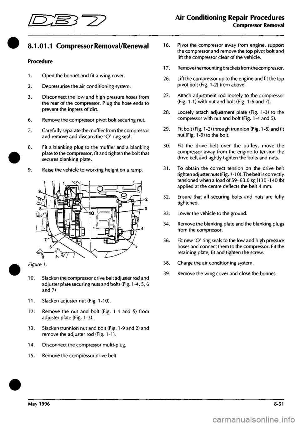
8.1.01.1 Compressor Removal/Renewal
Procedure
1.
Open the bonnet and fit a wing cover.
2.
Depressurise the air conditioning system.
3.
6.
7.
8.
9.
Disconnect the low and high pressure hoses from
the rear of the compressor. Plug the hose ends to
prevent the ingress of dirt.
Remove the compressor pivot bolt securing nut.
Carefully separate the muffler from the compressor
and remove and discard the 'O' ring
seal.
Fit a blanking plug to the muffler and a blanking
plate to the compressor, fit and tighten the bolt that
secures blanking plate.
Raise the vehicle to working height on a ramp.
Figure 7.
10.
Slacken the compressor drive belt adjuster rod and
adjuster plate securing nuts and bolts (Fig.
1
-4, 5, 6
and 7)
11.
Slacken adjuster nut (Fig.
1
-10).
12.
Remove the nut and bolt (Fig. 1-4 and 5) from
adjuster plate (Fig. 1-3).
13.
Slacken trunnion nut and bolt (Fig.
1
-9 and 2) and
remove the adjuster rod (Fig. 1-1).
14.
Disconnect the compressor multi-plug.
1
5. Remove the compressor drive belt.
16.
Pivot the compressor away from engine, support
the compressor and remove the top pivot bolt and
lift the compressor clear of the vehicle.
17.
Removethemountingbracketsfromthecompressor.
26.
Lift the compressor up to the engine and fit the top
pivot bolt (Fig.
1
-2) from above.
27.
Attach adjustment rod loosely to the compressor
(Fig.
1
-1) with nut and bolt (Fig.
1
-6 and 7).
28.
Loosely attach adjustment plate (Fig. 1-3) to the
compressor with nut and bolt (Fig.
1
-4 and 5).
29.
Fit bolt (Fig.
1
-2) through trunnion (Fig.
1
-8) and fit
nut (Fig. 1-9) to the bolt.
30.
Fit the drive belt over the pulley, move the
compressor away from the engine to tension the
drive belt and lightly tighten the bolts and nuts.
31.
To obtain the correct tension on the drive belt
tighten adjuster nuts
(Fig.
1
-10). The belt
is
correctly
tensioned when a load of 59- 63.6 kg (130 -140 lb)
applied at the centre deflects the belt 4 mm.
32.
Ensure that all securing bolts and nuts are fully
tightened.
33.
Lowerthe vehicle to the ground.
34.
Remove the blanking plate and the blanking plugs
from the compressor.
36.
Fit new 'O' ring seals to the low and high pressure
hoses and connect them to the compressor. Fit the
retaining plate, fit and tighten the screw.
38.
Charge the air conditioning system.
39.
Remove the wing cover and close the bonnet.
May 1996 8-51
Page 329 of 421
Air Conditioning Repair Procedures
Field Coil Renewal
/
Gasket Kit Renewal ffi^e^'^^
8.1.02.1 Field Coil Renewal 8.1.03.1 Renew Gasket
Kit
Procedure
1.
Open
the
bonnet
and fit a
wing cover.
2.
Depressurise
the air
conditioning system.
3. Remove
the
compressor.
4.
Remove
the
compressor drive clutch.
5. Remove
the
compressor pulley.
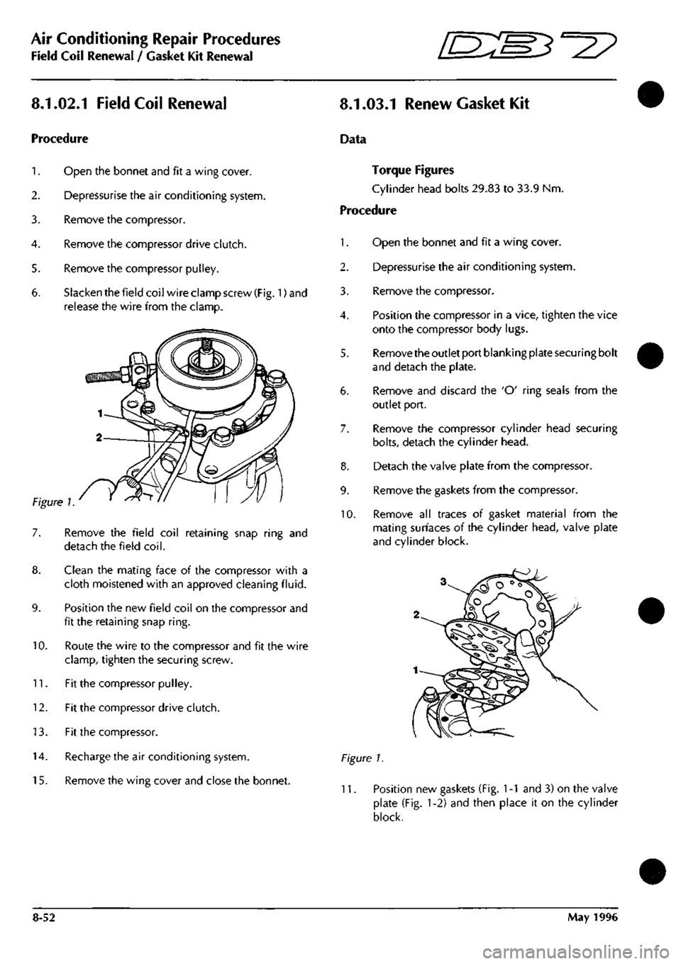
6. Slacken
the
field coil wire clamp screw
(Fig.
1) and
release
the
wire from
the
clamp.
10.
Remove
the
field coil retaining snap ring
and
detach
the
field
coil.
Clean
the
mating face
of the
compressor with
a
cloth moistened with
an
approved cleaning
fluid.
Position
the new
field coil
on the
compressor
and
fit
the
retaining snap
ring.
Route
the
wire
to the
compressor
and fit the
wire
clamp, tighten
the
securing screw.
11.
Fit the
compressor pulley.
12.
Fit the
compressor drive clutch.
13.
Fit the
compressor.
14.
Recharge
the air
conditioning system.
15.
Remove
the
wing cover
and
close
the
bonnet.
Data
Torque Figures
Cylinder head bolts 29.83
to 33.9 Nm.
Procedure
1.
Open
the
bonnet
and fit a
wing cover.
2.
Depressurise
the air
conditioning system.
3. Remove
the
compressor.
4.
Position
the
compressor
in a
vice, tighten
the
vice
onto
the
compressor body lugs.
5. Remove the outlet port blanking plate securing bolt
and detach
the
plate.
6. Remove
and
discard
the 'O'
ring seals from
the
outlet port.
7. Remove
the
compressor cylinder head securing
bolts,
detach
the
cylinder head.
8. Detach
the
valve plate from
the
compressor.
9. Remove
the
gaskets from
the
compressor.
10.
Remove
all
traces
of
gasket material from
the
mating surfaces
of the
cylinder head, valve plate
and cylinder block.
Figure
1.
11.
Position
new
gaskets (Fig.
1 -1
and 3) on the
valve
plate
(Fig. 1-2) and
then place
it on the
cylinder
block.
8-52 May
1996
Page 330 of 421
ES3^^
Air Conditioning Repair Procedures
Valve Plate Renewal
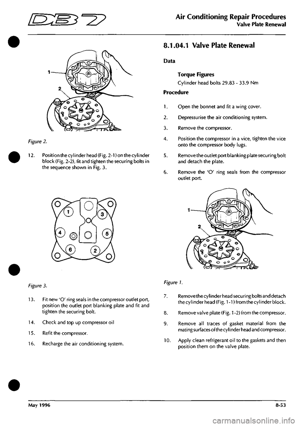
Figure
2.
12.
Position the cylinder head (Fig. 2-1) on the cylinder
block (Fig. 2-2), fit and tighten the securing bolts in
the sequence shown in Fig. 3.
8.1.04.1 Valve Plate Renewal
Data
Torque Figures
Cylinder head bolts 29.83 - 33.9 Nm
Procedure
1.
Open the bonnet and fit a wing cover.
2.
Depressurise the air conditioning system.
3. Remove the compressor.
4.
Position the compressor in a vice, tighten the vice
onto the compressor body lugs.
5. Remove the outlet port blanking plate securing bolt
and detach the plate.
6. Remove the 'O' ring seals from the compressor
outlet port.
figure 3.
13.
Fit new 'O' ring seals in the compressor outlet port,
position the outlet port blanking plate and fit and
tighten the securing bolt.
14.
Check and top up compressor oil
15.
Refit the compressor.
16.
Recharge the air conditioning system.
Figure 1.
7. Removethecylinder head securing boltsand detach
the cylinder head (Fig. 1-1) from the cylinder block.
8. Remove valve plate
(Fig.
1
-2) from the compressor.
9. Remove all traces of gasket material from the
mati
ng
surfaces of the cy
I
i nder
head
and compressor.
10.
Apply clean refrigerant oil to the gaskets and then
position them on the valve plate.
May 1996 8-53
Page 331 of 421
Air Conditioning Repair Procedures
Expansion Valve Renewal
ES^'^?
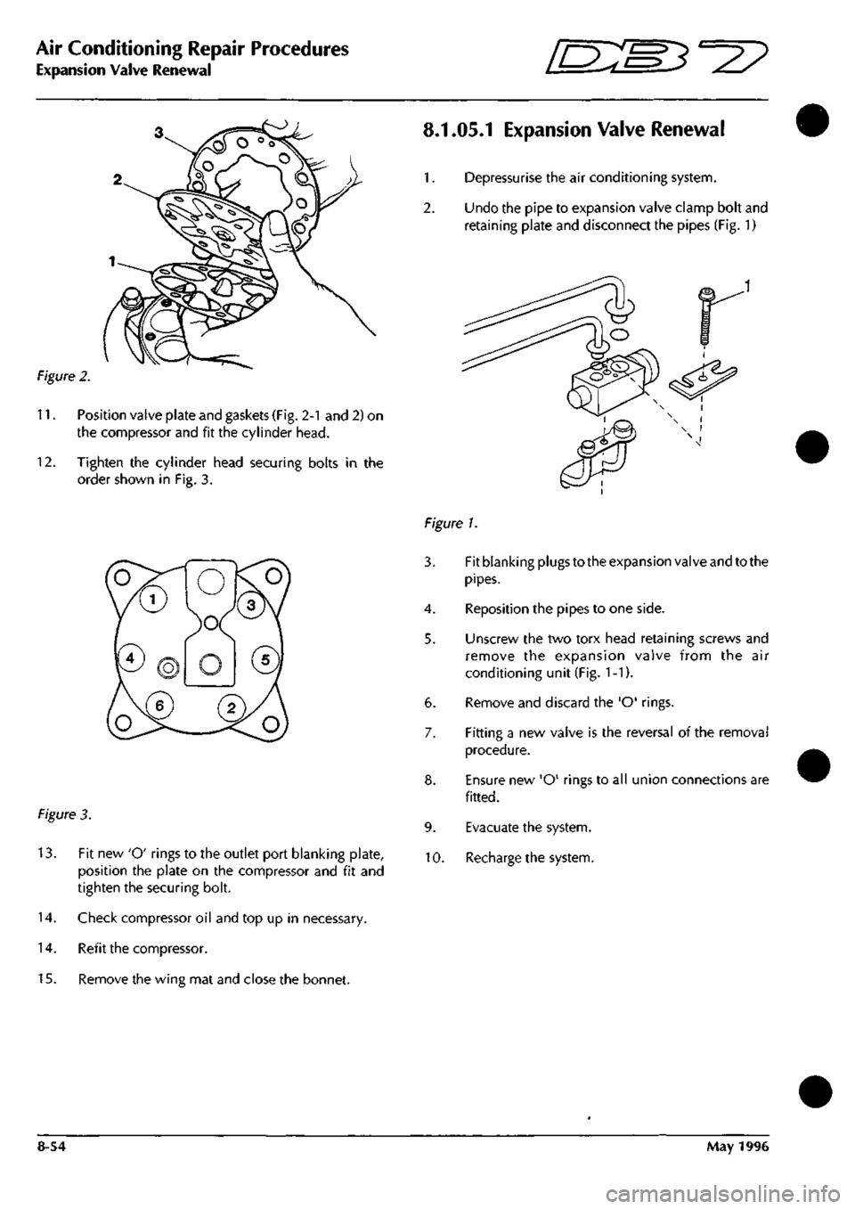
Figure 2.
11.
Position valve plate and gaskets (Fig. 2-1 and 2) on
the compressor and fit the cylinder head.
12.
Tighten the cylinder head securing bolts in the
order shown in Fig. 3.
Figure 3.
13.
Fit new 'O' rings to the outlet port blanking plate,
position the plate on the compressor and fit and
tighten the securing bolt.
14.
Check compressor oil and top up in necessary.
14.
Refit the compressor.
15.
Remove the wing mat and close the bonnet.
8.1.05.1 Expansion Valve Renewal
1.
Depressurise the air conditioning system.
2.
Undo the pipe to expansion valve clamp bolt and
retaining plate and disconnect the pipes (Fig. 1)
Figure 1.
3. Fit blanking plugs to the expansion valve and to the
pipes.
4.
Reposition the pipes to one side.
5. Unscrew the two torx head retaining screws and
remove the expansion valve from the air
conditioning unit (Fig.
1
-1).
6. Remove and discard the 'O' rings.
7. Fitting a new valve is the reversal of the removal
procedure.
8. Ensure new 'O' rings to all union connections are
fitted.
9. Evacuate the system.
10.
Recharge the system.
8-54 May 1996
Page 332 of 421
^2?
Air Conditioning Repair Procedures
Hose - Compressor to Evaporator/Air-Con Unit Renew
8.1.06.1 Hose-Compressor
to
Evaporator
Renewal
Procedure
1.
Open the bonnet and fit a wing cover.
2.
Depressurise the air conditioning systenn.
3. Remove the hose to evaporator valve clamping
plate,
disconnect the hose from the valve, remove
and discard the 'O' ring
seal.
4.
Fit a blanking plug to the evaporator valve. Release
the evaporator hose securing clips.
5. Remove the compressor outlet port retaining bolt.
6. Disconnect the hose from the compressor, discard
the hose complete with 'O' ring seals.
7. Connect the hose to the evaporator valve and
tighten clamp onto the hose.
8. Route the hose to the compressor, fit a new 'O' ring
seal and connect it to the compressor.
9. Position the outlet port retaining plate on the
compressor, fit and tighten the securing bolt.
10.
Refit the hose to the clips.
11.
Charge the air conditioning system.
12.
Remove the wing cover and close the bonnet.
8.2.01.1 Air Conditioning Unit Renewal
1.
Disconnect the battery earth
lead.
2.
Drain the engine coolant into a suitable container.
3. Depressurise the air conditioning system.
4.
Disconnect the high and low pressure hoses and
expansion valve from the air conditioning unit (see
expansion valve renewal).
5. Slacken the coolant hose to the heater matrix pipe
securing clips and disconnect the hoses from the
matrix. (This will require the removal of the air
intake hose for access.)
6. Remove the following items from inside the car:
front seats
underscuttle panels/knee bolsters
glove box assembly
facia trim (walnut trim)
radio and ashtray
centre console switch panel assembly
instrument panel and surround trim
steering wheel and column
facia assembly complete
hoses - distribution box to door vents
facia support frame
Details and drawings of the above operations can
be found in the electrical and trim sections.
Disconnect the vacuum hoses from the blower
motors, water valve and reservoir.
Un-clip the electrical harness from the air
conditioningunit, release theelectrical connections
and reposition the harness to allow removal of the
unit.
Displace and remove the footwell ventilator ducts
and hoses (Fig. 1-1).
May 1996 8-55
Page 333 of 421
Air Conditioning Repair Procedures
Air-Conditioning Unit Renew ^^?
10.
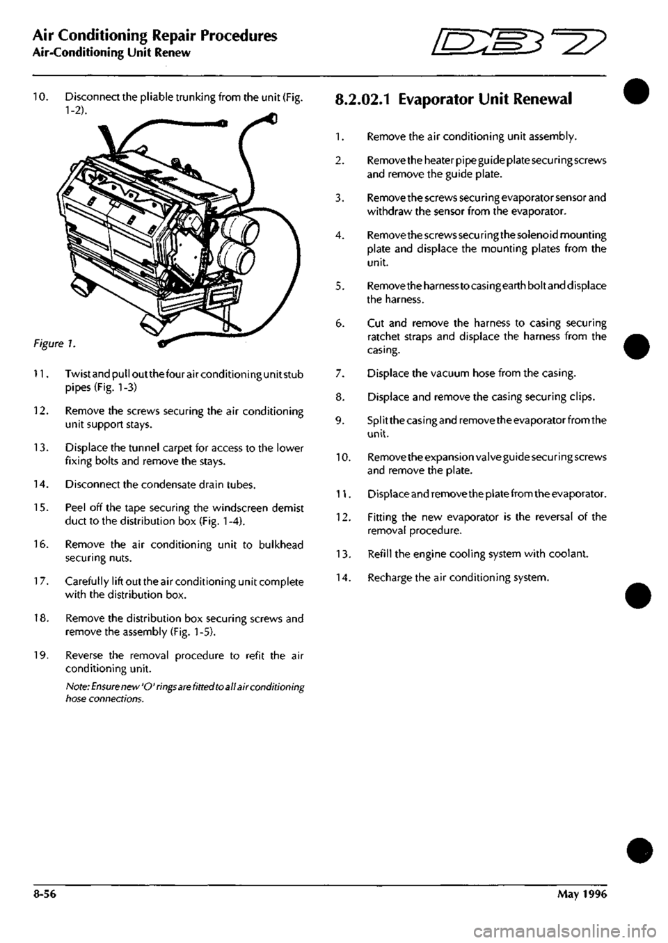
Disconnect the pliable trunking from the unit (Fig.
8.2.02.1
EvaporatOr Unit Renewal
1-2). ^
1.
Remove the air conditioning unit assembly.
2.
Remove the heater pipe guide plate securing screws
and remove the guide plate.
3. Remove the screws secu ri ng evaporator sensor and
withdraw the sensor from the evaporator.
4.
Remove the screws securing the solenoid mounting
plate and displace the mounting plates from the
unit.
5. Removetheharnesstocasingearthboltand displace
the harness.
6. Cut and remove the harness to casing securing
ratchet straps and displace the harness from the
casing.
7. Displace the vacuum hose from the casing.
8. Displace and remove the casing securing clips.
9. Splitthecasingandremovetheevaporatorfromthe
unit.
10.
Remove the expansion valve guide securing screws
and remove the plate.
11.
Displace and remove the plate from the evaporator.
12.
Fitting the new evaporator is the reversal of the
removal procedure.
13.
Refill the engine cooling system with coolant.
14.
Recharge the air conditioning system.
Figure 1
11.
Twistandpulloutthefourairconditioningunitstub
pipes (Fig. 1-3)
12.
Remove the screws securing the air conditioning
unit support stays.
13.
Displace the tunnel carpet for access to the lower
fixing bolts and remove the stays.
14.
Disconnect the condensate drain tubes.
15.
Peel off the tape securing the windscreen demist
duct to the distribution box (Fig.
1
-4).
16.
Remove the air conditioning unit to bulkhead
securing nuts.
1
7. Carefully lift out the air conditioning unit complete
with the distribution box.
18.
Remove the distribution box securing screws and
remove the assembly (Fig.
1
-5).
19.
Reverse the removal procedure to refit the air
conditioning unit.
Note:
Ensure new'O'rings
are
fitted toall air conditioning
tiose connections.
8-56 May 1996