window ASTON MARTIN DB7 1997 User Guide
[x] Cancel search | Manufacturer: ASTON MARTIN, Model Year: 1997, Model line: DB7, Model: ASTON MARTIN DB7 1997Pages: 421, PDF Size: 9.31 MB
Page 129 of 421
Electrics
Relay Location Index - 97 MY 5^^?
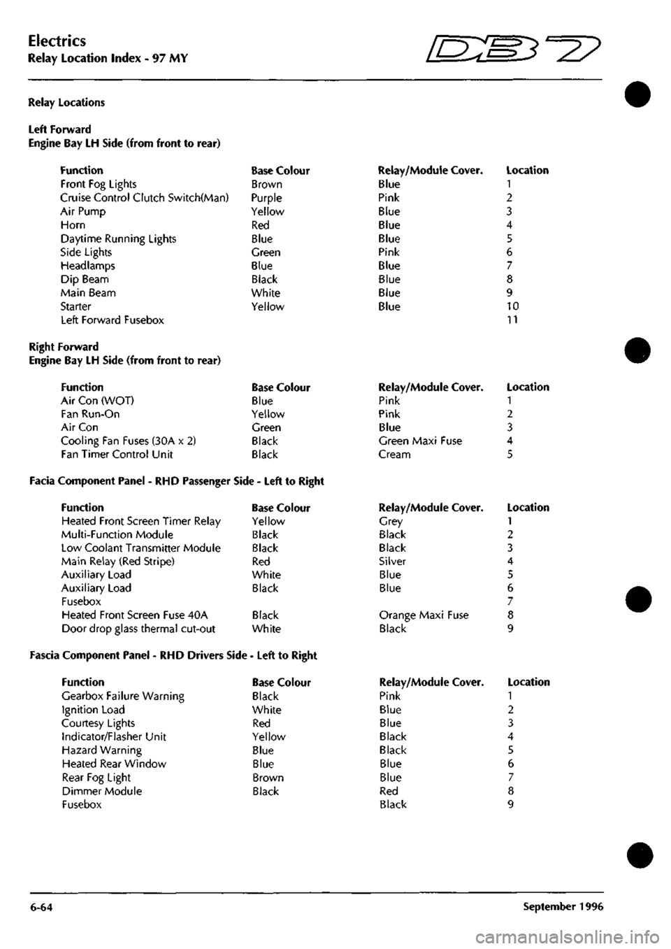
Relay Locations
Left Forward
Engine Bay LH Side (from front to
Function
Front Fog Lights
rear)
Cruise Control Clutch Switch(Man)
Air Pump
Horn
Daytime Running Lights
Side Lights
Headlamps
Dip Beam
Main Beam
Starter
Left Forward Fusebox
Base Colour
Brown
Purple
Yellow
Red
Blue
Green
Blue
Black
White
Yellow
Relay/Module Cover.
Blue
Pink
Blue
Blue
Blue
Pink
Blue
Blue
Blue
Blue
Location
1
2
3
4
5
6
7
8
9
10
11
Right Forward
Engine Bay LH Side (from front to rear)
Function Base Colour
Air Con (WOT) Blue
Fan Run-On Yellow
Air Con Green
Cooling Fan Fuses (30A x 2) Black
Fan Timer Control Unit Black
Facia Component Panel - RHD Passenger Side - Left to Right
Function Base Colour
Heated Front Screen Timer Relay Yellow
Multi-Function Module Black
Low Coolant Transmitter Module Black
Main Relay (Red Stripe) Red
Auxiliary Load White
Auxiliary Load Black
Fusebox
Heated Front Screen Fuse 40A Black
Door drop glass thermal cut-out White
Fascia Component Panel - RHD Drivers Side - Left to Right
Function
Gearbox Failure Warning
Ignition Load
Courtesy Lights
Indicator/Flasher Unit
Hazard Warning
Heated Rear Window
Rear Fog Light
Dimmer Module
Fusebox
Base Colour
Black
White
Red
Yellow
Blue
Blue
Brown
Black
Relay/Module
Pink
Pink
Blue
Cover.
Green Maxi Fuse
Cream
Relay/Module
Grey
Black
Black
Silver
Blue
Blue
Cover.
Orange Maxi Fuse
Black
Relay/Module
Pink
Blue
Blue
Black
Black
Blue
Blue
Red
Black
Cover.
Location
1
2
3
4
5
Location
1
2
3
4
5
6
7
8
9
Location
1
2
3
4
5
6
7
8
9
6-64 September 1996
Page 131 of 421
Electrics
Relay Location Index - 97 MY
D^^
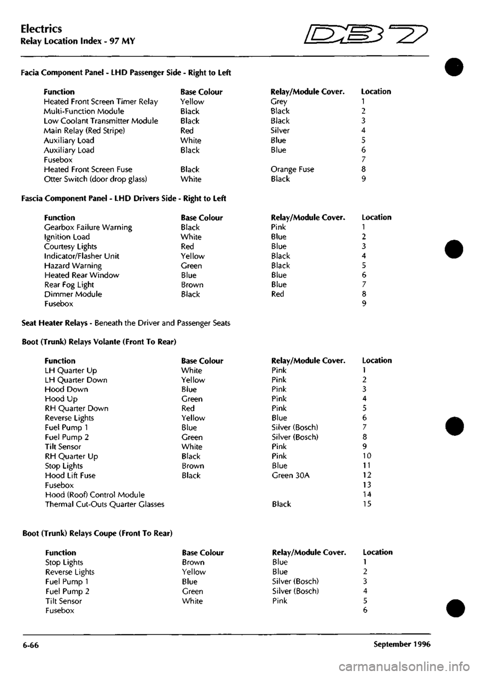
Facia Component Panel
- LHD
Passenger
Function
Heated Front Screen Timer Relay
Multi-Function Module
Low Coolant Transmitter Module
Main Relay (Red Stripe)
Auxiliary Load
Auxiliary Load
Fusebox
Heated Front Screen Fuse
Otter Switch (door drop glass)
Side
-
Right
to
Left
Base Colour
Yellow
Black
Black
Red
White
Black
Black
White
Fascia Component Panel
- LHD
Drivers Side
-
Right
to
Left
Function
Gearbox Failure Warning
Ignition Load
Courtesy Lights
Indicator/Flasher Unit
Hazard Warning
Heated Rear Window
Rear
Fog
Light
Dimmer Module
Fusebox
Base Colour
Black
White
Red
Yellow
Green
Blue
Brown
Black
Relay/Module Cover.
Grey
Black
Black
Silver
Blue
Blue
Orange Fuse
Black
Relay/Module Cover.
Pink
Blue
Blue
Black
Black
Blue
Blue
Red
Location
1
2
3
4
5
6
7
8
9
Location
1
2
3
4
5
6
7
8
9
Seat Heater Relays - Beneath the Driver and Passenger Seats
Boot (Trunk) Relays Volante (Front To Rear)
Function
LH Quarter
Up
LH Quarter Down
Hood Down
Hood
Up
RH Quarter Down
Reverse Lights
Fuel Pump
1
Fuel Pump
2
Tilt Sensor
RH Quarter
Up
Stop Lights
Hood Lift Fuse
Fusebox
Hood (Roof) Control Module
Thermal Cut-Outs Quarter Glasses
Base Colour
White
Yellow
Blue
Green
Red
Yellow
Blue
Green
White
Black
Brown
Black
Relay/Module Cover.
Pink
Pink
Pink
Pink
Pink
Blue
Silver (Bosch)
Silver (Bosch)
Pink
Pink
Blue
Green
30A
Black
Location
1
2
3
4
5
6
7
8
9
10
11
12
13
14
15
Boot (Trunk) Relays Coupe (Front To Rear)
Function
Stop Lights
Reverse Lights
Fuel Pump 1
Fuel Pump 2
Tilt Sensor
Fusebox
Base Colour
Brown
Yellow
Blue
Green
White
6-66
Relay/Module
Blue
Blue
Silver (Bosch)
Silver (Bosch)
Pink
Cover. Location
1
2
3
4
5
6
September
1996
Page 158 of 421

CIGAR LIGHTER
NO COLOUR 735 B 347 RW
746 8 818 RG 819 OR RH
1
1 4 5
AREA l3.B3-2ieA 15.B5-JI9A
I3.B3-2I84 13.86 I3.B6 WINDOW SWITCH
NO COLOUR PIN AREA 730 8 I l3.B3-2ieA 820 GP 2 13.86 329 RW I3.B5-2I9AI
0 0
[D
CRUISE ON/OFF SWITCH
•*• NO COLOUR 725 B 2203 YO 2201 LGY 2204 YO 307 RW
PIN 1 2 3 4
AREA 13.B3-2I8A 13.B4-2I9 I3.B4-2I8 13.84-219 I3.B5-2I9A
NO COLOUR AREA 729 8 I3.C3-2I8A
RIP
D
CRUISE SET SWITCH
•*• NO COLOUR 230 U 825 BP 2205 LGY 177 Y 343 RW
PIN 1 2 3 4
AREA I3.B3 I3.B6 I3.B4-2I8 13.86 I3.B5-2I9A
NO COLOUR AREA 734 B 13.C3-219A
0
D
NO COLOUR 817 YO 818 RG 819 GR 379 RU 380 GU 820 6P S2I RW 177 Y 825 BP 731 U 2202 LGY
332 8
PIN 1 ? 3 4 5 6 7 8 9 10 II 12 13 14 15 16
AREA 13.84-219 I3.A2 I3.A2 I3.D2 13.02 I3.A3 I3,B5-2I9A I3.A5 I3.B5 I3.B3 I3.B4-2I8
IS.B3-2I8A
SHEET II AREA Dl
GEAR SELECTOR ILLUMINATION
LH WINDOW SWITCH
NO COLOUR PIN AREA 331 RW I 13.B5-219A 705 6 2 l3.B3-2ieA NO COLOUR PIN 748 B 342 RW
778
B
379 RU 380 GU
AREA l3.B3-2ieA I3.B5-2I9A
I3.B3-2I8A 13.66 13.86 ^7 Wiring Diagram
Model - Aston Martin DB7
Harness Title - Console
Part No. - B37-84638
Revision - 0 Sheet 13 of 26-97 MY
Page 164 of 421
NO
COLOUR
PIN
AREA I0S8
KB I
I7.B3-I79 JAO
OC 2 H.BI
WINDOW LIFT NO COLOUR
PIN
AREA I0S3
GR I
I6.A3 1051
GW 2
I6.A3
I
NO
COLOUR AREA 1829
RN
I4.BI
I HEATED BACKLIGHTi
VAPOUR MANAGEMENT VALVE
HOOD LIFT NO COLOUR 1054
GW
1053
GR
1060 GW lOEl
GR
1
I
4
I
AREA I6.AI le.AI
I5.ei-I54A I5.BI-I54B
NO COLOUR
PIN
1096 BW 828
BG
AREA I4.AI I4.BI
I4.B5-I60 I4.BI
FUEL PUMP
I
NO COLOUR
PIN
1086
B 1
1087 UG
2
AREA I6.B3 I7.A2
NO COLOUR
PIN
AREA 16.85 I7.A3
INTERIOR LIGHT NO COLOUR
PIN
AREA
1056 P I I4.C4-I56 1057 PW 2 I4.C4-I57
m
fsD
1ST SECURITY STEM
I
AERIAL
I
NO
COLOUR
PIN
799
BR I
1800
B 2
AREA 14.Al 14.Al
I
NO
COLOUR ||055
TIN
AREA I7.B6
LINK PINS
I a 2
LING
PIN 3 a 4
NO COLOUR
PIN
AREA
1062
NP
792
VG
I6.B3-I68 I4.AI
6)[5]o[4)|3J
02 01 Qi 03
REAR LAMP
SHORTING
PLUG
02 01 Ql 03
NO COLOUR PINAREA
1064
GP I
IG.B5-I74
1065 GP
2 16.01 1066 RU 3 I4.C5-I59
1067
RU 4 16,01
Ql D3 D2 01
LINK PINS
I 8 4
RH REAR LAMP
NO COLOUR 1067
RU
1068
ON
1069 CW 1070
B
1071
RG
1065
GP
PIN 1 ? ^ 4 •) 6
AREA 16.01 I6.B3-I7I I6.BI-I67 I6.C3-IG9 I6.C3-I70 16.01
mmra CEIinnn
(—\ Qi 01
cr
D 0 I—I 03 06 SHEET 18 '• AREA B/CI
0
01 Qi 0 D 03 06
NO COLOUR AREA 813
LGO 14.01
1080
B
I6.B4-I73 FUEL TANK SENDER UNIT
NO COLOUR AREA 1086
B
1088
B
1090
B
1091
B
I6.A5 I6.A6 16.84-173 I6.C3-I69
TH^
SHEET 17 AREA Bl
-» ^
-F^Pl-'
NO COLOUR
PIN
AREA
1094
BR U
16.86-178
1095 BR W 16.84-172
NO COLOUR PIN 797 S I
1092
B 2
652
WU 3
1093
HP 4
AREA 14.01
I6.B4-I73 14.01 I6.B5-I75
NO COLOUR AREA 2183
B
I6.C5-2I8 1084 RG
16.04
RADIO TELEPHONE
E
Di 05 D 0 D D 04 08/
4
8
J^Q a
£o 0 PO 0
T?D 0 ^ 1 S ^
NO COLOUR
PIN
1081
BR I
1082 PG
2
3
NO COLOUR AREA
1078
NP
I6.B3-I68 1079
BR
I6.B4-I72
AREA I6.B4-I72 I7.C6
1084
RG 1085 B 16.03-170 I6.B4-I73
NO COLOUR
PIN
1081
BR I
1082
PG 2
3 i
RS 4
5 6 1084 RG
7
1085
B 8
AREA le.CG 16.CG
I6.C6 I6.C5-2I8
Zl
1
RH NUMBER PLATE LAMP
NO COLOUR
PIN
AREA 1081
BR I
I6.C4 2184
B 2
l6.C5-2ia
BOOT LOCK ACTUATOR NO COLOUR
PIN
AREA 2185
B I
I6.C5-2I8 1082
PG 2
I6.C4
^[}
[}
JLH
NUMBER
PLATE LAMP
NO COLOUR AREA 2186
B
I6.C5-2I6 ;I083
RS
I6.D4
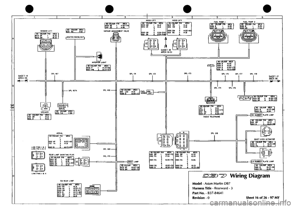
Wiring Diagram
Model - Aston Martin DB7
Harness Title - Rearward - 3
Part No. -
B3
7-84641
Revision - 0 Sheet 16 of 26-97 MY
Page 174 of 421

NO COLOUR PIN AREA 1233 BP I 2LC4-2I3 1234 8 2 2I,A4-2I2 3
MICRO SWITCH NO COLOUR PIN AREA 371 OU I 2I.B6 373 OR 2 2I.B6 1235 B 3 2I.B5-209 LOCK SWITCH
NO COLOUR 1241 B 1242 RN 1243 1 1244 Y6 1245 YU
PIN 1 ? 3 4 5
AREA 2I.A4-2I2 2I.B4-2II 2I.B5-205 2I.C5-206 2LB5-207
NO COLOUR PIN 372 OW I 370
OG
2
AREA 2I.B6 2I.B6
LOCK MOTOR [am
L.H DOOR MIRROR NO COLOUR PIN 1236 B 1 1237 RM 2 1238 Y 3 1239 YR 4 1240 YB 5
AREA 2I,A4-2I2 2LB4-2II 21.85-205 2I.C5-20B 2LB4-2IO i0©j R.H OOOR MIRROR
NO COLOUR AREA 1246 B 2I.A4-2I2 1247 B 21.85-209
X
WINDOW ECU
(am
(-
("
1 13 • • Q 0 D D DOZ^ D D D D D D
• D DOZ D Q D 0 G 0
NO COLOUR PIN 966 8 I 967
BW
2
AREA 21.86 2I.B6
REAR GUARD LAMP
NO COLOUR PIN AREA 385 LG 1249 BP 379 R
380
G
1248
8
386
NU
A B C D E F 6
2I.C6 2LC4-2I3 2I.B6 2I.B6
2I.B5-209 2I.C6
DOOR MIRROR SWITCH
NO
COLOUR
1250
YR
1251
YG
1252
Y
1253
LG
1254
YU
1230
8
1255
YB
PIN 1 ? 3 4 5 6
7 8
AREA 21.05-209 2I.C5-206 2LB5-205 2I.C6 2LA4-207 2L85-2I2 21,04-210
NO
COLOUf
370
00
371
OU
372
OW
373
OR
375
8
376
BW
377
PG
376
PW
379
R
380
G
381
YG
362
YU
383
Y
1230
LG
385
LG
386
NU
387
BP
388
RN
389
8
1231
YR
1232
YB
PIN 1 2 i
4 5 6
7 8 9 10 II 12 13 14 15 16 17 IB 19 20 71 22
AREA
21.81
2I.A2
21.81
2I.BI
2I.A2 2I.C5 2I.D2
21.02
2I.D2
21.03
21.03-206 2I.C5-207 2I.B5-205 2I.D5 2I.D3 2I.D3 2LC4-2I3 2I.C4-2II 21,85-209 2I.C5-208 2I.C4-2I0
SHEET 8 AREA Dl
NO COLOUR PIN 377P 1 378 PW 2 3
AREA 21.86 21.86 Wiring Diagram
Model - Aston Martin DB7
Harness Title - Drivers Door
Part No. - B3
7-84646
Revision - 0 Sheet 21 of 26-97 MY
Page 176 of 421

NO COLOUR
PIN
ARE*
1222
BP I
22.CA-Z0A
1223 B 2 22*4-203 3
MICRO SWITCH
KO COLOUR
PIN
ARE* 9S2
OU I
22.B6
984
OR 2
22.B6 1224
B 3
22.B5-200 LOCK SWITCH
NO COLOUR 1207
6
1208
RN 1209 t 1210 TG 1211 YU
PIN 1 ? 3 4 5
AREA 22.A4-203 22.B4-202 22.85-196 22.C5-I97 22.85-198
NO COLOUR PIN AREA 391 OW I 22.B6 389
OG
2 22.86
in LOCK MOTOR g] [J
L.H DC NO COLOUR
1225
B
1226
RN
1227
Y
1228
YR 1229 YB
PIN 1 2 3 4 5
OR MIRROR AREA 22.A4-203 22.B4-202 22.85-196 22.C5-I99 22.84-201
R.H DOOR MIRROR
NO COLOUR AREA
1212
B
22.A4-203
1213 B 22.85-200
SHEET 12 ^2> C=. AREA C6 ^* 1**^
SPL 200 SPL 198
n n 'I "TT
SPL
201
SPL 199
¥mpD'
c
1"
1 13
D
D
D
a D 0 00=1 D 0 0 0 Q 0 Q Q DDC D 0 D 0 D 0
NO COLOUF 981
06
982
OU
983
OW
984
OR
986
B
987
BW
988
PO
989
PW
818
RG
819
CR
381
YG
382
YU
383
Y
1206
LC
990
LO
991
NU
992
8P
993
RN
994
B
1204
YR
1205
YB
PIN 1 2 3
4 5 6
1 8 9 10 II 12 13 14 15 16 17 18 19 20 21 22
AREA 22.BI 22.A2 22.BI 22.A2
22.C5 22.C5 22.02 22.02 22.03 22.03 22.C5-197 22.B5-I98 22.B5-I96 22.D3 22.D3 22.03 22.C4-204 22.C4-202 22.B5-200 22.C5-I99 22.C4-20I
NO COLOUR
PIN
AREA
986 8 I 22.B6 987
BW
2
22.B6
WINDOW ECU
REAR GUARD LAMP
NO COLOUR PIN 990 LG A
1221
BP B
818
R C
819
G D
220
B
991
NU
AREA 22.C6 22.C4-204 22.86 22.B6
22.B5-200 22.C6
DOOR MIRROR SWITCH
NO
1214 1215 1216 1217 1218
1206 1219
COLOUR YR YG Y LG YU B YB
PIN 1 ? 3 4 5 6 7 8
AREA 22.C5-I99 22.C5-I97 22.85-196 22.C6 22.A4-I98 22.B5-203 22.C4-20I
NO COLOUR PIN AREA 988 PG I 22.B6 989 PW 2 22.B6 3
[D:[B3-=2? Wiring Diagram
Model - Aston Martin DB7
Harness Title - Passengers Door
Part No. - B37-84647
Revision - 0 Sheet 22 of 26 - 97 MY
Page 187 of 421
^=2?
Electrics
Airbag System
Eye Protection
Chemical protective goggles are recommended
where there is a possibility of eye contact with the
propellant. Safety glasses with side shields are
recommended for all other operations.
Protective Clothing
Approved protective gloves, overalls and shoes/
boots should be worn.
Handling and Storage Precautions
Do not store airbag modules near live electrical
equipment or circuitry. Store in a dry environment
at ambient temperatures.
Good housekeeping and engineering practices
should be employed to prevent the generation and
accumulation of
dusts.
Store in compliance with all
local state and federal regulations.
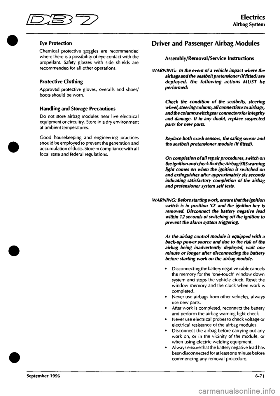
Driver and Passenger Airbag Modules
Assembly/Removal/Service Instructions
WARNING: In the event of a vehicle impact where the
airbags and the seatbeltpretensioner (if fitted) are
deployed, the following actions MUST be
performed:
Check the condition of the seatbelts, steering
wheel,
steering column, all connections to airbags,
and the column switchgear connectors for integrity
and damage. If in any
doubt,
replace suspected
parts for new parts.
Replace both crash
sensors,
the
safing sensor
and
the seatbelt pretensioner module (if fitted).
On completion of all repair procedures, switch on
the ignition and check that the
Airbag/SRS
warning
light comes on when the ignition is switched on
and extinguishes after approximately six seconds
indicating satisfactory completion of the airbag
and pretensioner
system
self
tests.
WARNING: Before starting
work,
ensure
that the ignition
switch is in position 'O' and the ignition key is
removed.
Disconnect the battery negative lead
within 12 seconds of switching off the ignition to
prevent the alarm system triggering.
As the airbag control module is equipped with a
back-up power source and due to the risk of the
airbag being inadvertently deployed, wait one
minute or longer after disconnecting the battery
before starting work on the airbag module.
• Disconnectingthe battery negative cable cancels
the memory for the 'one-touch' window down
system and stops the vehicle clock. Reset the
window memory and the clock when work is
completed.
• Never use airbags from other vehicles, always
use new parts.
• After work is completed, reconnect the battery
and perform the airbag warning light check
• Never use electrical probes to check voltage or
electrical resistance of the airbag modules.
• Disconnect the airbag before carrying out any
work on, or in the vicinity of the module, or
when using electric welding equipment.
• Always ensure that the battery negative lead has
been disconnected for at least one minute before
commencing any removal procedure.
September 1996 6-71
Page 189 of 421
^^
Electrics
Airbag System
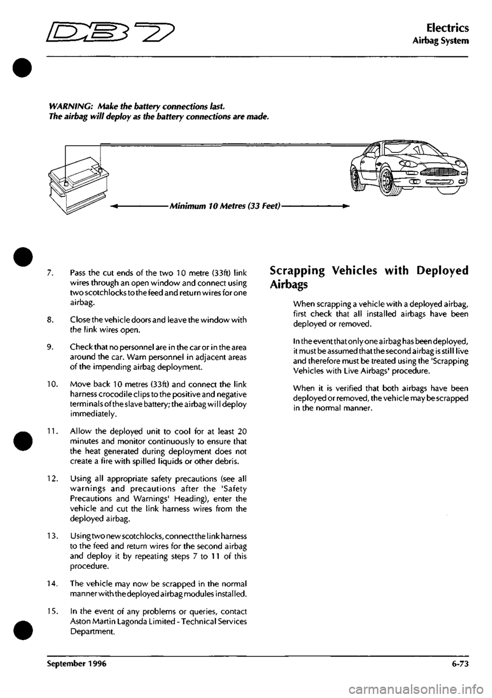
WARNING: Make the battery connections
last.
The airbag will deploy as the battery connections are made.
Minimum 10 Metres (33 Feet)-
7. Pass the cut ends of the two 10 metre (33ft) link
wires through an open window and connect using
two scotchlocks to the feed and return wires for one
airbag.
8. Closethe vehicle doors and leave the window with
the link wires open.
9. Check that no personnel are in the car or in the area
around the car. Warn personnel in adjacent areas
of the impending airbag deployment.
10.
Move back 10 metres (33ft) and connect the link
harness crocodile clips to the positive and negative
terminals ofthe slave battery; the airbag will deploy
immediately.
11.
Allow the deployed unit to cool for at least 20
minutes and monitor continuously to ensure that
the heat generated during deployment does not
create a fire with spilled liquids or other debris.
12.
Using all appropriate safety precautions (see all
warnings and precautions after the 'Safety
Precautions and Warnings' Heading), enter the
vehicle and cut the link harness wires from the
deployed airbag.
13.
Usingtwonewscotchlocks,connectthelinkharness
to the feed and return wires for the second airbag
and deploy it by repeating steps 7 to 11 of this
procedure.
14.
The vehicle may now be scrapped in the normal
manner with thedeployed airbag modules installed.
15.
In the event of any problems or queries, contact
Aston Martin Lagonda Limited - Technical Services
Department.
Scrapping Vehicles
Air bags
with Deployed
when scrapping a vehicle with a deployed airbag,
first check that all installed airbags have been
deployed or removed.
In the eventthatonly one airbag has beendeployed,
it must be assumed thatthe second airbag is still live
and therefore must be treated using the 'Scrapping
Vehicles with Live Airbags' procedure.
when it is verified that both airbags have been
deployed or removed, the vehicle may
be
scrapped
in the normal manner.
September 1996 6-73
Page 191 of 421
'=2?
Electrics
Airbag System
4.5.01.3 Driver's Airbag Module Renew
Read and adhere to all warnings and safety
procedures quoted at the start of this section when
working on airbag modules.
1.
Ensure that the steering system is centralised and
that the steering wheel is in the lowest tilt position.
2.
Disconnect the vehicle battery and insulate the
battery lead to avoid accidental reconnection. Wait
for at least one minute before proceeding with work
on the removal of the airbag.
Hote: The vehicle battery
must be
disconnected within
12 seconds of switching off
the
ignition to avoid the alarm
siren sounding.
5. Carefully remove the module from the steering
wheel and disconnect the airbag module multi-
plug.
6. To ensure personal safety, double check that the
battery is still disconnected and the battery lead
safely insulated. Connect the new airbag module
multi-plug.
Fit and align the new module to the
steering wheel and tighten the two securing torx
screws. Return the steering to the straight ahead
position.
7. Remove the battery lead insulation and reconnect
the battery
lead.
Note:
The vehicle
clockandthe window control unitwill
need
resetting
after completion of
this
procedure.
8. Switch on the ignition and check that the airbag
warni ng
I
ight comes on when the ignition is switched
on and extinguishes after approximately sixseconds
indicating satisfactory completion of the airbag
system self tests.
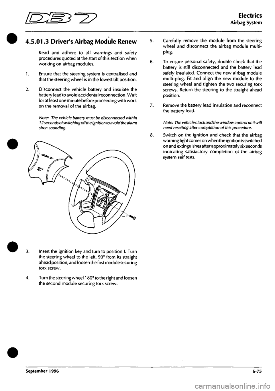
Insert the ignition key and turn to position I. Turn
the steering wheel to the left, 90° from its straight
ahead position, and loosen thefirstmoduiesecuring
torx screw.
Turn the steering wheehSO" to the rightand loosen
the second module securing torx screw.
September 1996 6-75
Page 192 of 421
Electrics
Airbag System ^^?
7.8.02.6
Renew
Passenger's Airbag Module
Read and adhere to all warnings and safety
procedures quoted at the start of this section when
working on airbag modules.
Disconnect the battery and wait for at least one
minute before proceeding with the airbag removal.
Note:
The
vehicle battery
must
be disconnected within
12
seconds
of switchingoff
the
ignition
to
avoid the alarm
siren sounding.
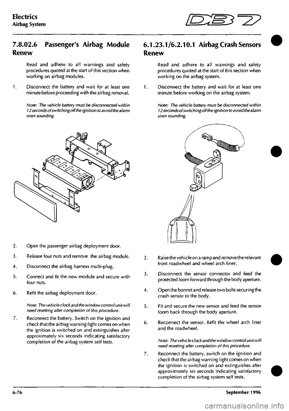
2. Open the passenger airbag deployment door.
3. Release four nuts and remove the airbag module.
4.
Disconnect the airbag harness multi-plug.
5. Connect and fit the new module and secure with
four nuts.
6. Refit the airbag deployment door.
Note:
The vehicle
clock and
the
window control unit will
need
resetting
after completion of
this
procedure.
7. Reconnect the battery. Switch on the ignition and
check that the airbag warning
I
ight comes on when
the ignition is switched on and extinguishes after
approximately six seconds indicating satisfactory
completion of the airbag system self tests.
6.1.23.1/6.2.10.1 Airbag
Crash
Sensors
Renew
Read and adhere to all warnings and safety
procedures quoted at the start of this section when
working on the airbag system.
1.
Disconnect the battery and wait for at least one
minute before working on the airbag system.
Note: The vehicle
battery
must be disconnected within
12
seconds
of switchingoff
the
ignition
to
avoid thealarm
siren sounding.
4.
5.
Raisethevehicleon a rampand remove the relevant
front roadwheel and wheel arch liner.
Disconnect the sensor connector and feed the
protected loom forward through the body aperture.
Open the bonnet and release two bolts securing the
crash sensor to the body.
Fit and secure the new sensor and feed the sensor
loom back through the body aperture.
Reconnect the sensor. Refit the wheel arch liner
and the roadwheel.
Note:
The vehicle
clock and
the
window control unit will
need
resetting
after completion of
this
procedure.
Reconnect the battery, switch on the ignition and
check that the airbag warning
I
ight comes on when
the ignition is switched on and extinguishes after
approximately six seconds indicating satisfactory
completion of the airbag system self tests.
6-76 September 1996