torque ASTON MARTIN V8 VANTAGE 2010 User Guide
[x] Cancel search | Manufacturer: ASTON MARTIN, Model Year: 2010, Model line: V8 VANTAGE, Model: ASTON MARTIN V8 VANTAGE 2010Pages: 947, PDF Size: 43.21 MB
Page 39 of 947

Body Closures (01.03)
Body System (01.00)
May 2007 Workshop Manual 1-3-13
3. Remove LH quarter upper trim panel (see Workshop
Manual procedure 01.05.CY Moulding Assembly -
Quarter Trim Upper - LH - Renew).
4. Remove rear header trim panel (see Workshop Manual procedure 01.05.BK Panel Assembly - Rear Header -
Renew).
5. Disconnect LH and RH tailgate harnesses in cabin
6. Remove LH and RH harness grommets from body.
7. Remove tailgate trim panel (see Workshop Manual procedure 01.05.EF Trim - Tailgate Lid Assembly -
Renew).
8. Disconnect GPS antenna mult iplug, remove bolts (x3),
remove GPS antenna.
9. Disconnect multiplug form central high stop lamp, remove nuts (x2), remove central high stop lamp.
10. Disconnect multiplug from tailgate release switch,
remove nuts (x2), remove tailgate release switch.
11. Remove tailgate buffer stops (x2).
12. Install protection between tailgate corners and bodywork.
13. Release clips, disconnect gas struts (x2) from tailgate.
14. With assistance, remove bolt s (x4) securing tailgate to
hinges, remove tailgate assembly.
Installation
1. With assistance, install and align tailgate to hinges, install bolts (x4). Do not torque tighten at this stage.
2. Adjust alignment of tailgate and torque tighten hinge bolts.
3. Connect gas struts to tailgate and secure with clips.
4. Install tailgate buffers and adjust height as necessary
5. Install tailgate release switch, install and tighten nuts (x2), connect multiplug.
6. Install central high level st op lamp assembly, install and
tighten nuts (x2), connect multiplug.
7. Install GPS antenna, install and tighten bolts (x3), connect multiplug.
8. Install tailgate trim panel (see Workshop Manual procedure 01.05.EF Trim - Tailgate Lid Assembly -
Renew).
9. Install rear header trim panel (see Workshop Manual procedure 01.05.BK Panel Assembly - Rear Header -
Renew).
10. Install LH upper quarter trim panel (see Workshop Manual procedure 01.05.CY Moulding Assembly -
Quarter Trim Upper - LH - Renew).
11. Install RH upper quarter trim panel (see Workshop Manual procedure 01.05.CX Moulding Assembly -
Quarter Trim Upper - RH - Renew).
12. Remove protection from tailgate and body.
13. Battery isolation switch ‘ON’.
Tailgate Hinge Assembly (Pair) - Renew
Removal
1. Protect bodywork.
2. Mark position of hinges.
3. With assistance support and hold tailgate.
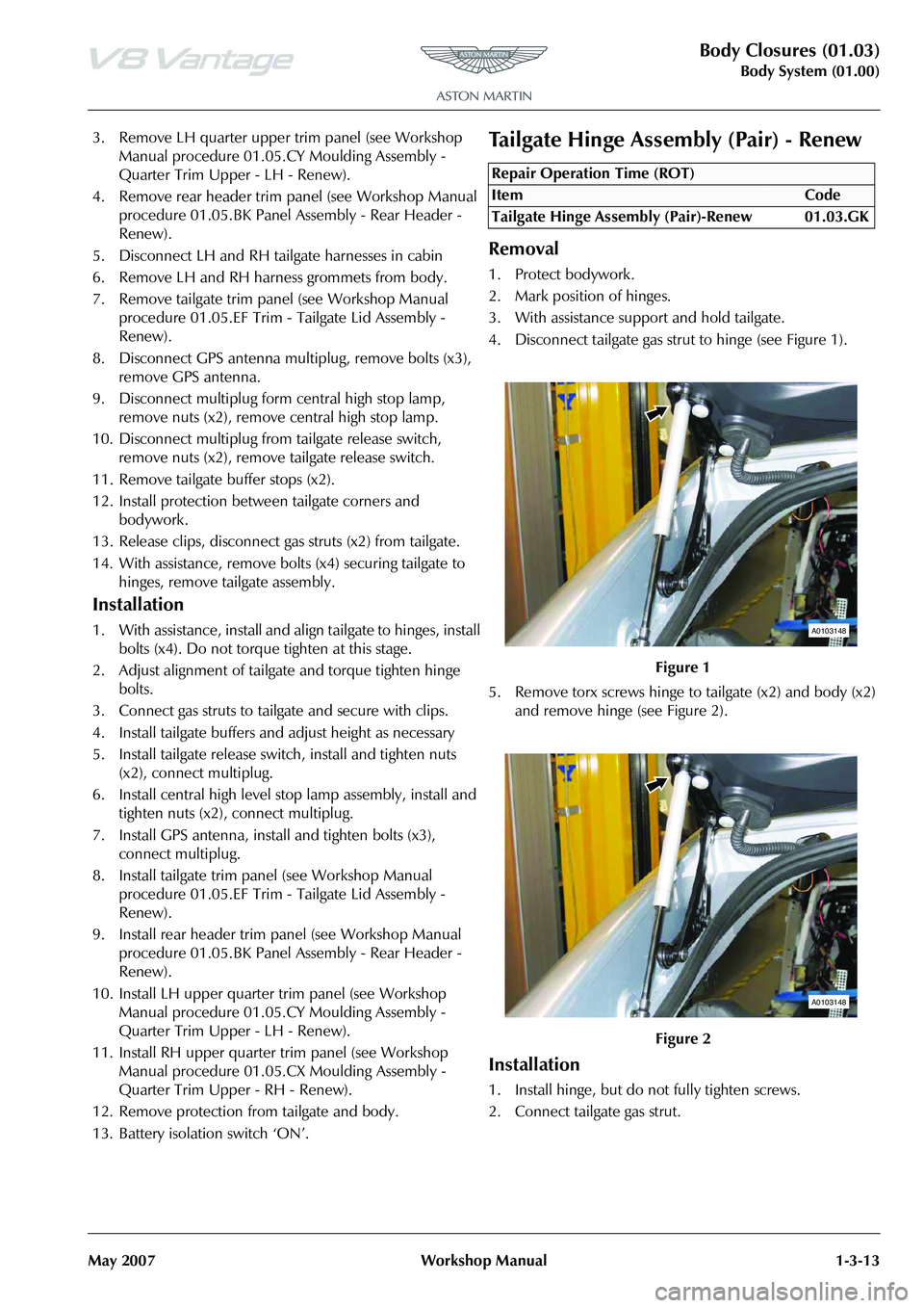
4. Disconnect tailgate gas strut to hinge (see Figure 1).
5. Remove torx screws hinge to tailgate (x2) and body (x2) and remove hinge (see Figure 2).
Installation
1. Install hinge, but do not fully tighten screws.
2. Connect tailgate gas strut.
Repair Operation Time (ROT)
A0103148
A0103148
Page 40 of 947

Body Closures (01.03)
Body System (01.00)1-3-14 Workshop Manual May 2007
3. Repeat remove and installa tion procedure for opposite
hinge (see Figure 1).
4. Check alignment of tailgate and adjust as necessary.
5. Fully tighten screws (x8) tailgate hinges.
6. Remove bodywork protection.
Hood Assembly - Renew
Removal
1. Open hood.
2. Disconnect windscreen wash pipe.
3. Remove cap nut, nut and release earth lead from hood.
4. Remove buffers from hood.
5. Remove Torx screws (x2) se curing striker plate to hood,
remove striker plate.
6. Remove Torx screws (x2) se curing safety catch to hood,
remove safety catch.
7. Remove hood sound insulation.
8. Remove cap nuts (x12) securing air intake grilles (x2) to
hood, remove grilles.
9. Disconnect screen washer hos e, reservoir to non-return
valve.
10. Loosen hood hinge bolts (4).
11. Disconnect gas struts and remove hinge bolts
12. With assistance, remove bolts (x4) and hood.
13. Remove ball studs from bonnet.
14. Remove screen washer jets (x2) and hoses from hood.
Installation
1. Install and torque tighten ball studs (x2).
2. Install screen washer hoses and jets (x2).
3. With assistance, position hood to hinges, install bolts
(x4). Do not torque tighten at this stage. 4. Install safety catch, install and torque tighten Torx
screws (x2).
5. Install striker plate, install and torque tighten Torx screws (x2).
6. Install air intake grilles (x2), install and tighten cap nuts (x12).
7. Install Buffers to hood.
8. Install sound insulation.
9. Align hood to aperture.
10. Raise hood and tighten up one hinge bolt either side.
11. Lower hood and check alignment
12. Raise hood and torque tighten hinge bolts (x4).
13. Install gas struts.
14. Install earth lead to hood, install and tighten nut and cap nut.
15. Connect screen washer hose.
16. Close hood to check enga gement of latch assembly,
adjust if necessary
17. Close hood and check operation of hood release lever.
Hood Hinge Assembly (Vehicle Set) -
Renew
Removal
1. Remove LH wing (see Workshop Manual procedure 01.02.LB Panel Assembly - Front Wing - LH - Renew).
2. Remove RH wing (see Workshop Manual procedure 01.02.KB Panel Assembly - Front Wing - RH - Renew).
3. Protect bodywork.
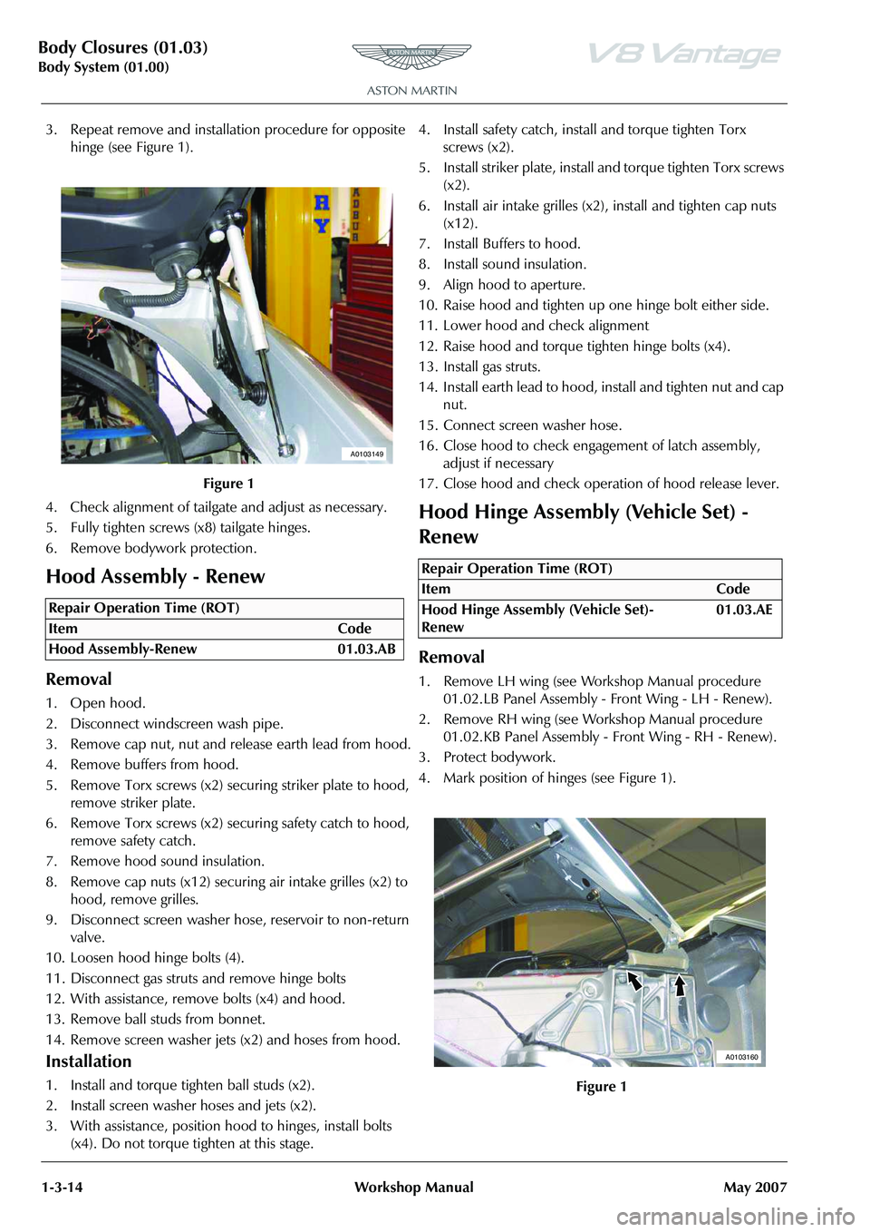
4. Mark position of hinges (see Figure 1).
Figure 1
Repair Operation Time (ROT)
A0103149
Repair Operation Time (ROT)
ItemCode
Hood Hinge Assembly (Vehicle Set)-
Renew 01.03.AE
Figure 1
A0103160
Page 62 of 947

Exterior Trim (01.08)
Body System (01.00)1-5-2 Workshop Manual May 2007
RH Wing Side Strake - Renew
Removal
1. Disconnect vehicle battery.
2. Raise vehicle on ramp.
3. Remove mesh - RH side strake (see Workshop Manual procedure 01.08.CE Mesh - Side Strake - RH - Renew).
4. Remove Torx screw, (inside A-post) securing side strake to body.
5. Remove nut securing side strake to RH inner fender.
6. Remove side strake.
Installation
1. Install side strake, install and tighten nut and Torx screw.
2. Install mesh - RH side strake (see Workshop Manual procedure 01.08.CE Mesh - Side Strake - RH - Renew).
3. Lower vehicle on ramp.
4. Connect vehicle battery.
LH Wing Side Strake - Renew
Removal
1. Raise vehicle on ramp.
2. Remove mesh - LH side strake (see Workshop Manual procedure 01.08.CF Mesh - Side Strake - LH - Renew).
3. Remove nuts (x3) mesh to side strake.
4. Remove mesh.
5. Remove screw inside A-post side strake to body.
6. Remove nut side strake to wheel arch.
7. Remove side strake.
Installation
1. Install side strake, nut and screw.
2. Position mesh to side strake and install nuts (x3).
3. Install mesh - LH side strake (see Workshop Manual procedure 01.08.CF Mesh - Side Strake - LH - Renew).
4. Lower vehicle on ramp.
Channel Assembly Divider Bar - Renew
Removal
1. Remove window regulator (see Workshop Manual procedure 01.11.DA Regulator - Door Glass - RH -
Renew). 2. Remove fixed glass (see Workshop Manual procedure
01.11.BG Glass - Front Door - Fixed RH - Renew).
3. Remove seal.
4. Remove screw, divider bar to mirror (see Figure 1).
5. Remove nut (hold stud with Allen key) divider bar to door and remove (see Figure 2).
Installation
1. Install bar and nut (hold stud with Allen key).
2. Install screw, divider bar to mirror (Do not tighten at this point).
3. Install seal.
4. Adjust bar. Rotate Allen stud in centre in/out until desired alignment of bar is achieved, then torque fixings.
5. Install fixed glass (see Workshop Manual procedure 01.11.BG Glass - Front Door - Fixed RH - Renew).
6. Install window regulator (see Workshop Manual procedure 01.11.DA Regulator - Door Glass - RH -
Renew).
Repair Operation Time (ROT)
Repair Operation Time (ROT)
Repair Operation Time (ROT)
Figure 1
Figure 2
A0108170
A0108171
Page 65 of 947

Mirrors (01.09)
Body System (01.00)
May 2007 Workshop Manual 1-6-1
Body System (01.00)
Mirrors (01.09)
Specifications
Maintenance
LH Door Mirror Assembly - Renew
Removal
1. Remove door trimboard (see Workshop Manual
procedure 01.05.CB Trimboard Assembly - Door -
Remove for Access and Refit).
Torque Figures
DescriptionNm
Mirror Mounting 20-25
Repair Operation Time (ROT)
A010808
Figure 2
Repair Operation Time (ROT)
A010807
Page 67 of 947

Seating (01.10)
Body System (01.00)
Issue 4, November 2008 Workshop Manual 1-7-1
Body System (01.00)
Seating (01.10)
Description
The front seats are installed with the following features:
• Integral side airbags
•Head restraints
• Safety belt reel pretensioner
• Electrically adjustable seat positioning and lumbar support
• Heated seat (optional)
Heated Seats
The heated seat system comprises:
• Heated seat switches
• Backrest heater element
• Cushion heater element and thermostat
The heated seat function permits the electrical heating of the
seat back and cushion on the driver and front passenger
seats. The heating system of each seat is selected by separate
switches located on the inside of each seat base.
Once the heated seat function has been activated, it will
operate until one of the following conditions have been
satisfied:
• A fixed period of time has expired (10 minutes)
• If the engine is not running and the ignition key is removed
• A malfunction is detected by the heated seat module
Confirmation that the heated seat function is active is
indicated by the illumination of an amber light on the
switch.
Specifications Maintenance
RH/LH Front Seat - Remove and Install
Remove
1. Power seat fully forward.
2. Remove bolts (x2), securing rear of seat to seat rails.
3. Power seat fully rearwards.
4. Disconnect vehicle battery.
5. Remove bolt securing se
at belt to seat frame.
6. Remove bolts (x2), securing front of seat to seat rails.
7. Tip the seat forwards and disconnect multiplugs (x4).
8. Protect sill plate and trim prior to seat removal.
9. With assistance, remove seat assembly.
Install
1. With assistance, Install seat in the vehicle.
2. Position seat belt to seat frame, install and torque tighten bolt.
3. Tip the seat forwards and connect multiplugs (x4).
4. Position seat onto seat rails.
5. Remove sill plate protection.
6. Connect vehicle battery.
7. Install front bolts (x2. Power seat forward and install rear bolts (x2). Torque tighten bolts (x4).
Front Seat Squab Cover Assembly (Each,
Pre-08MY) - Remove and Install
Remove
1. Remove seat (see Workshop Manual procedure 01.10.AB Seat Assembly - Front - LH - Remove for
Access and Refit).
Torque Figures
DescriptionNm
Seat mountings 20-25
Seatbelt 15-20
Repair Operation Time (ROT)
Repair Operation Time (ROT)
Page 69 of 947

Seating (01.10)
Body System (01.00)
Issue 4, November 2008 Workshop Manual 1-7-3
8. Release cover from seat back shell (strip x2 /clips x9) (see Figure 7).
9. Release cover from bottom of seat back shell (see Figure 8). 10. Push cover through to front
of seat, release strip, ease
from foam (velcro strips) and remove cover (see Figure
9).
Installation
1. Install cover over foam attach to velcro, secure strip and push through seat.
2. Secure cover to seat back shell.
3. Secure cover to bottom of seat back shell.
4. Secure cover to seat back shell (studs and velcro).
5. Install airbag module (bolt x1) (torque).
6. Install multiplug bracket fixing.
7. Connect airbag multiplug and secure to bracket.
8. Install lever cover.
9. Install release lever.
10. Install seat (see Workshop Manual procedure 01.10.AB Seat Assembly - Front - LH - Remove for Access and
Refit).
Front Seat Squab Cover Assembly (Each,
from 08MY) - Remove and Install
Remove
Information to follow
Front Seat Cushion Cover Assembly
(Each)-Renew
Figure 7
Figure 8
A0110298
A0110298A
Figure 9
Repair Operation Time (ROT)
Repair Operation Time (ROT)
A0110297
Page 72 of 947

Seating (01.10)
Body System (01.00)1-7-6 Workshop Manual Issue 4, November 2008
16. Slide 6 way height adjuster to release and remove adjuster from seat assembly (see Figure 5).
Installation
1. Install relay to seat cushion base.
2. Connect multiplugs (x3) and secure to 6 way adjuster frame.
3. Secure seat belt buckle harness (cable ties x4) to 6 way seat adjuster frame assembly.
4. Install a new bolt that attaches the seat belt buckle.
5. Position 6 way height adju ster to seat cushion frame
assembly and install screws (x4).
6. With assistance, install seat in the vehicle.
7. Position seat belt to seat frame, install and torque tighten bolt.
8. Tip seat forwards and connect multiplugs (x4).
9. Position seat onto seat rails.
10. Battery isolation switch ‘ON’.
11. Install front bolts (x2), Power seat forward and install rear bolts (x2). Torque tighten bolts (x 4).
Squab Motor Kit - Renew
Removal
1. Remove squab cover (see Workshop Manual procedure 01.10.AC Cover Assembly - Front Seat Squab - Each -
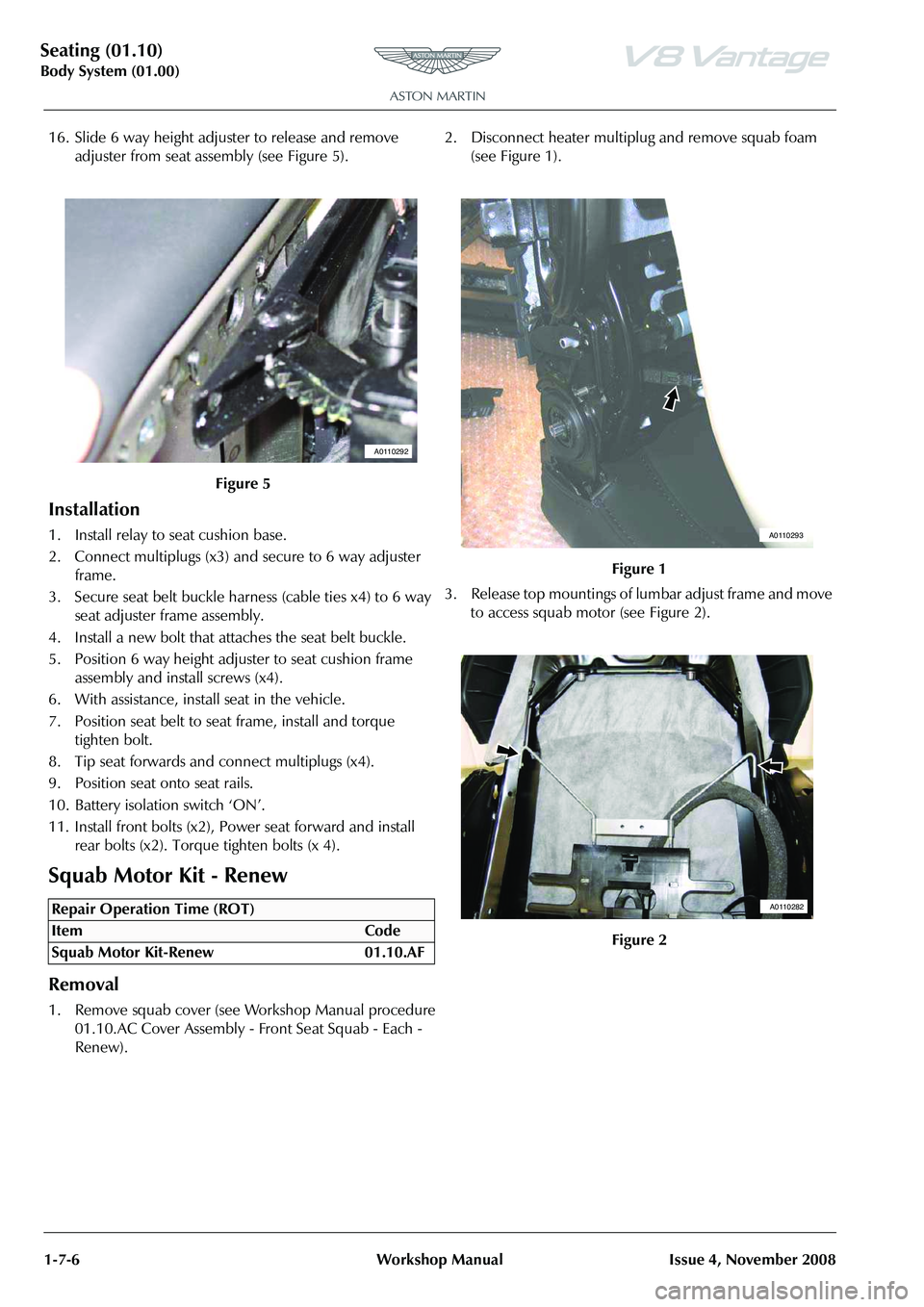
Renew). 2. Disconnect heater multiplug and remove squab foam
(see Figure 1).
3. Release top mountings of lumbar adjust frame and move to access squab motor (see Figure 2).
Figure 5
Repair Operation Time (ROT)
A0110292
Figure 1
Figure 2
A0110293
A0110282
Page 74 of 947

Seating (01.10)
Body System (01.00)1-7-8 Workshop Manual Issue 4, November 2008
4. Disconnect lumbar motor multiplug (see Figure 3).
5. Remove lumbar support fr om seat frame (screws x2)
(see Figure4).
Installation
1. Install lumbar support to seat frame (screws x2).
2. Connect lumbar motor multiplug.
3. Install seat back shell (rivets x4).
4. Connect heater multiplug and install squab foam.
5. Install squab cover (see Workshop Manual procedure 01.10.AC Cover Assembly - Front Seat Squab - Each -
Renew).
Side Airbag - Renew
Removal
1. Remove seat (see Workshop Manual procedure 01.10.AB Seat Assembly - Front - LH - Remove for
Access and Refit).
2. Remove lever cover (manoeuvre over lever).
3. Disconnect airbag multiplu g and release from bracket
(see Figure 1).
4. Remove fixing multiplug br acket, move aside (see Figure
2).
5. Remove (slide down) airbag module (bolt x1).
Installation
1. Install airbag module (bolt x1) (torque).
2. Install multiplug bracket fixing.
3. Connect airbag multiplug and secure to bracket.
4. Install lever cover (manoeuvre over lever).
5. Install seat (see Workshop Manual procedure 01.10.AB
Seat Assembly - Front - LH - Remove for Access and
Refit).
Figure 3
Figure 4
Repair Operation Time (ROT)
A0110284
A0110284A
Figure 1
Figure 2
A0110281
A0110281A
Page 75 of 947

Seating (01.10)
Body System (01.00)
Issue 4, November 2008 Workshop Manual 1-7-9
Front Seat Buckle Assembly - Renew
Removal
1. Power seat fully forward.
2. Remove bolts (x2) securing rear of seat to seat rails.
3. Power seat fully rearwards.
4. Remove bolts (x2) securing front of seat to seat rails.
5. Battery isolation switch ‘OFF’.
6. Remove bolt securing seat belt to seat frame.
7. Tip the seat forwards and disconnect multiplugs (x4).
8. With assistance, remove seat assembly.
9. Release multiplug (x1) seat belt buckle harness to 6 way
seat adjuster frame assembly.
10. Release cable ties (x4) securing seat belt buckle harness to 6 way seat adjuster frame assembly (see Figure 1). 11. Remove bolt (x1) seat belt buckle to frame (see Figure
2).
12. Remove seat belt buckle assembly.
Installation
1. Secure harness and multiplug to 6 way seat adjuster frame assembly.
2. Install seat belt buckle.
3. With assistance, install seat in the vehicle.
4. Position seat belt to seat frame, install and torque tighten bolt.
5. Tip seat forwards and connect multiplugs (x4).
6. Position seat onto seat rails.
7. Battery isolation switch ‘ON’.
8. Install front bolts (x2), Power seat forward and install rear bolts (x2). Torque tighten bolts (x 4).
Valance Heater and Lumbar Switch
Assembly - Renew
Removal
1. Power seat fully forward.
2. Remove bolts (x2) securing rear of seat to seat rails.
3. Power seat fully rearwards.
4. Remove bolts (x2) securing front of seat to seat rails.
5. Disconnect vehicle battery.
Repair Operation Time (ROT)
A0110289B
Figure 2
Repair Operation Time (ROT)
A0110287A
Page 76 of 947

Seating (01.10)
Body System (01.00)1-7-10 Workshop Manual Issue 4, November 2008
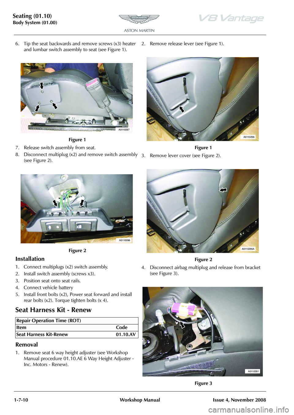
6. Tip the seat backwards and remove screws (x3) heater and lumbar switch assembly to seat (see Figure 1).
7. Release switch assembly from seat.
8. Disconnect multiplug (x2) and remove switch assembly (see Figure 2).
Installation
1. Connect multiplugs (x2) switch assembly.
2. Install switch assembly (screws x3).
3. Position seat onto seat rails.
4. Connect vehicle battery
5. Install front bolts (x2), Power seat forward and install rear bolts (x2). Torque tighten bolts (x 4).
Seat Harness Kit - Renew
Removal
1. Remove seat 6 way height adjuster (see Workshop Manual procedure 01.10.AE 6 Way Height Adjuster -
Inc. Motors - Renew). 2. Remove release lever (see Figure 1).
3. Remove lever cover (see Figure 2).
4. Disconnect airbag multiplu
g and release from bracket
(see Figure 3).
Figure 1
Figure 2
Repair Operation Time (ROT)
A0110287
A0110286
Figure 1
Figure 2
Figure 3
A0110296
A0110296A
A0110281