BATTERY SUPPLY ASTON MARTIN V8 VANTAGE 2010 Owner's Manual
[x] Cancel search | Manufacturer: ASTON MARTIN, Model Year: 2010, Model line: V8 VANTAGE, Model: ASTON MARTIN V8 VANTAGE 2010Pages: 947, PDF Size: 43.21 MB
Page 697 of 947
Wiring and Circuit Protection (18.01)
Electric Distribution/E lectronic Control (18.00)
18-1-8 Workshop Manual May 2007
Relays
Another significant component in the circuits is a relay, this
is in simple terms a switch that operates on the principal of
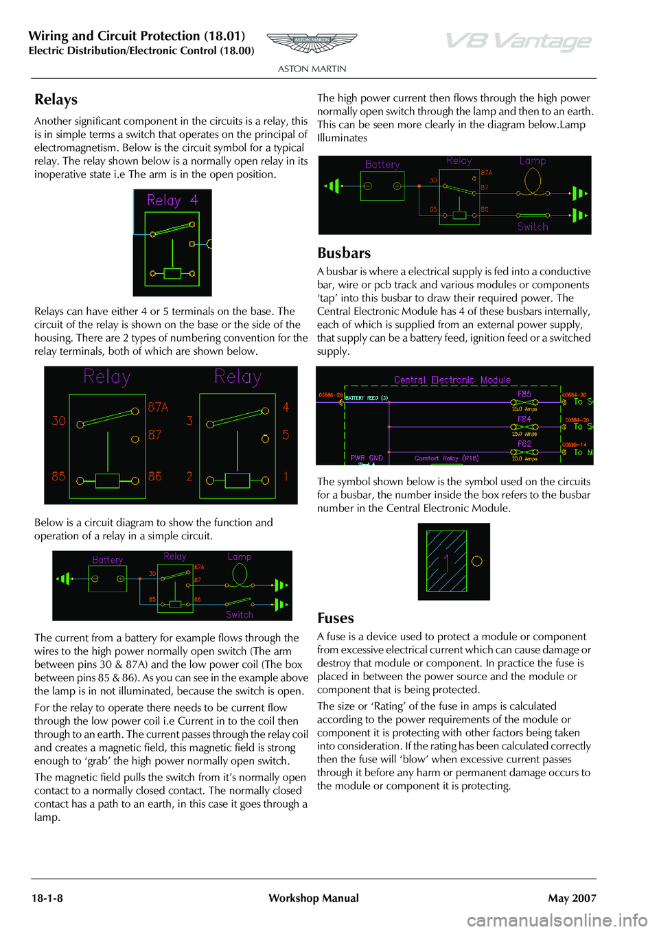
electromagnetism. Below is the circuit symbol for a typical
relay. The relay shown below is a normally open relay in its
inoperative state i.e The arm is in the open position.
Relays can have either 4 or 5 terminals on the base. The
circuit of the relay is shown on the base or the side of the
housing. There are 2 types of numbering convention for the
relay terminals, both of which are shown below.
Below is a circuit diagram to show the function and
operation of a relay in a simple circuit.
The current from a battery for example flows through the
wires to the high power normally open switch (The arm
between pins 30 & 87A) and the low power coil (The box
between pins 85 & 86). As you can see in the example above
the lamp is in not illuminated, because the switch is open.
For the relay to operate there needs to be current flow
through the low power coil i.e Current in to the coil then
through to an earth. The current passes through the relay coil
and creates a magnetic field, this magnetic field is strong
enough to ‘grab’ the high power normally open switch.
The magnetic field pulls the switch from it’s normally open
contact to a normally closed contact. The normally closed
contact has a path to an earth, in this case it goes through a
lamp. The high power current then flows through the high power
normally open switch through the lamp and then to an earth.
This can be seen more clearly in the diagram below.Lamp
Illuminates
Busbars
A busbar is where a electrical
supply is fed into a conductive
bar, wire or pcb track and various modules or components
‘tap’ into this busbar to draw their required power. The
Central Electronic Module has 4 of these busbars internally,
each of which is supplied from an external power supply,
that supply can be a battery feed, ignition feed or a switched
supply.
The symbol shown below is the symbol used on the circuits
for a busbar, the number inside the box refers to the busbar
number in the Central Electronic Module.
Fuses
A fuse is a device used to protect a module or component
from excessive electrical current which can cause damage or
destroy that module or component. In practice the fuse is
placed in between the power source and the module or
component that is being protected.
The size or ‘Rating’ of the fuse in amps is calculated
according to the power requirements of the module or
component it is protecting with other factors being taken
into consideration. If the rating has been calculated correctly
then the fuse will ‘blow’ when excessive current passes
through it before any harm or permanent damage occurs to
the module or component it is protecting.
Page 836 of 947
Electronics Training Programme
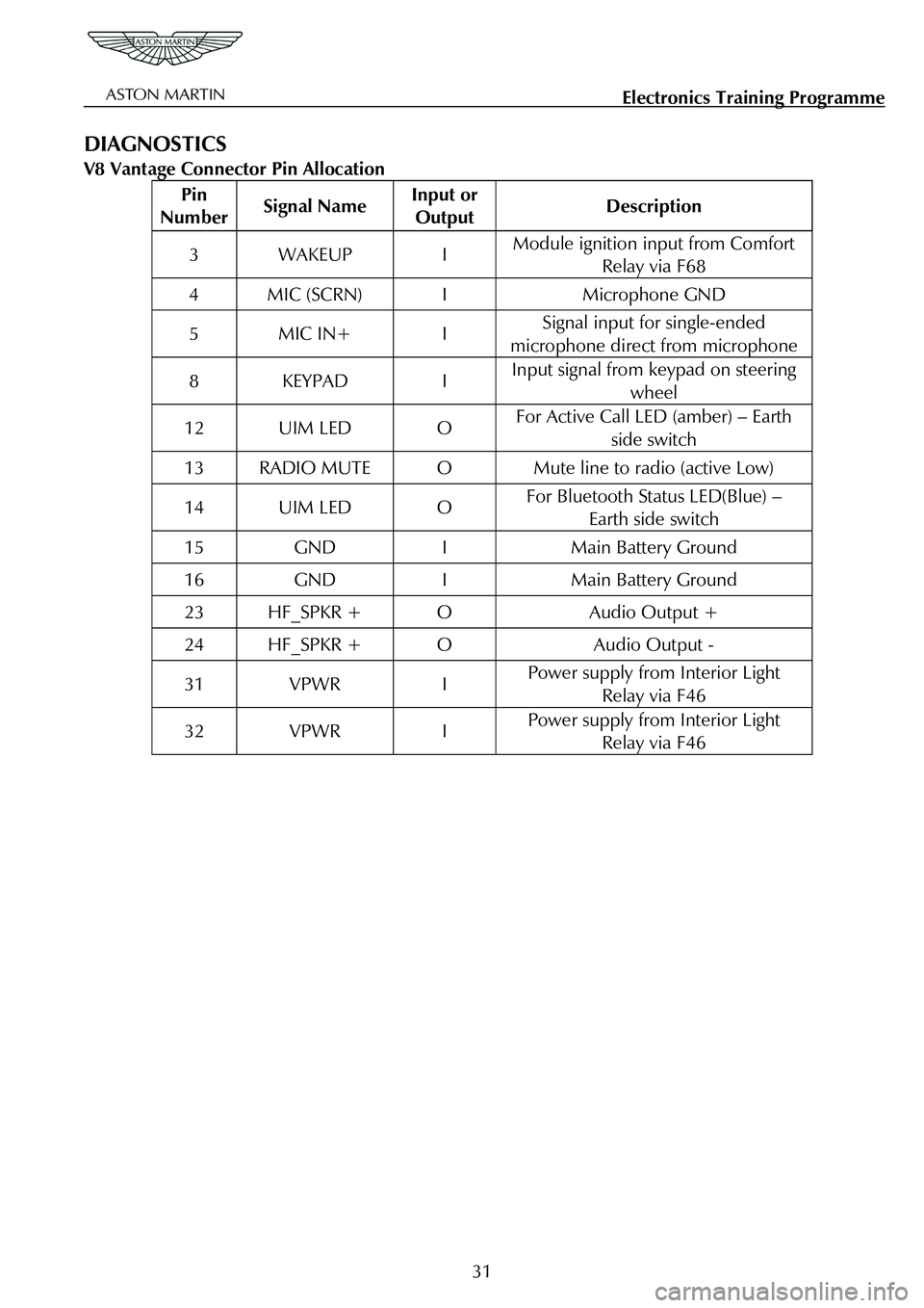
DIAGNOSTICS
V8 Vantage Connector Pin Allocation
Pin
Number Signal Name Input or
Output Description
3 WAKEUP I Module ignition input from Comfort
Relay via F68
4 MIC (SCRN) I Microphone GND
5 MIC IN+ I Signal input for single-ended
microphone direct from microphone
8 KEYPAD I Input signal from keypad on steering wheel
12 UIM LED O For Active Call LED (amber) – Earth
side switch
13 RADIO MUTE O Mute line to radio (active Low)
14 UIM LED O For Bluetooth Status LED(Blue) – Earth side switch
15 GND I Main Battery Ground
16 GND I Main Battery Ground
23 HF_SPKR + O Audio Output +
24 HF_SPKR + O Audio Output -
31 VPWR I Power supply from Interior Light Relay via F46
32 VPWR I Power supply from Interior Light Relay via F46
31
Page 837 of 947
Electronics Training Programme
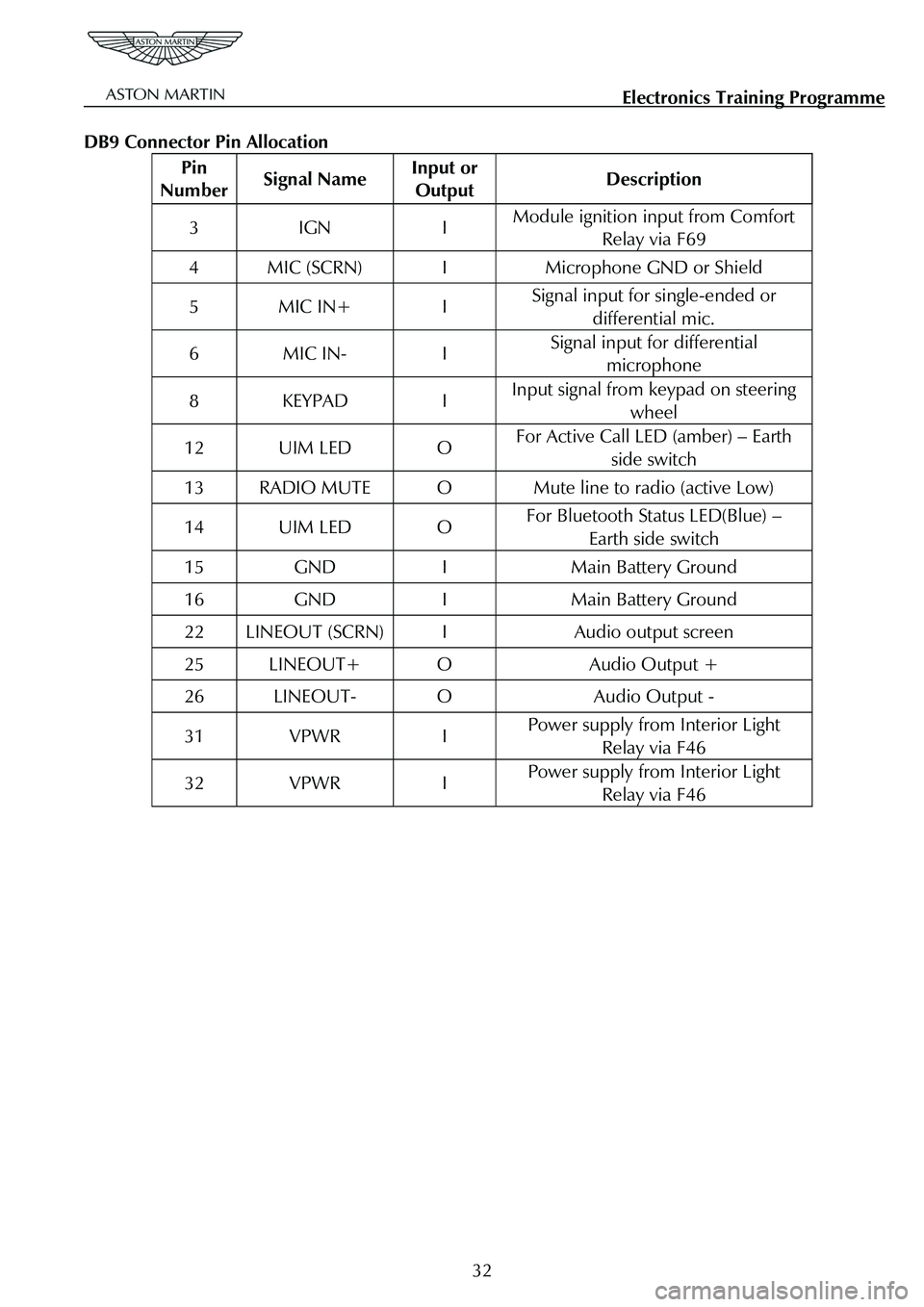
DB9 Connector Pin Allocation
Pin
Number Signal Name Input or
Output Description
3 IGN I Module ignition input from Comfort
Relay via F69
4 MIC (SCRN) I Microphone GND or Shield
5 MIC IN+ I Signal input for single-ended or
differential mic.
6 MIC IN- I Signal input for differential microphone
8 KEYPAD I Input signal from keypad on steering
wheel
12 UIM LED O For Active Call LED (amber) – Earth side switch
13 RADIO MUTE O Mute line to radio (active Low)
14 UIM LED O For Bluetooth Status LED(Blue) – Earth side switch
15 GND I Main Battery Ground
16 GND I Main Battery Ground
22 LINEOUT (SCRN) I Audio output screen
25 LINEOUT+ O Audio Output +
26 LINEOUT- O Audio Output -
31 VPWR I Power supply from Interior Light Relay via F46
32 VPWR I Power supply from Interior Light Relay via F46
32
Page 905 of 947
Aston Martin V8 Vantage2009MY OBDII Documentation 4.7L Aston Martin Confidential
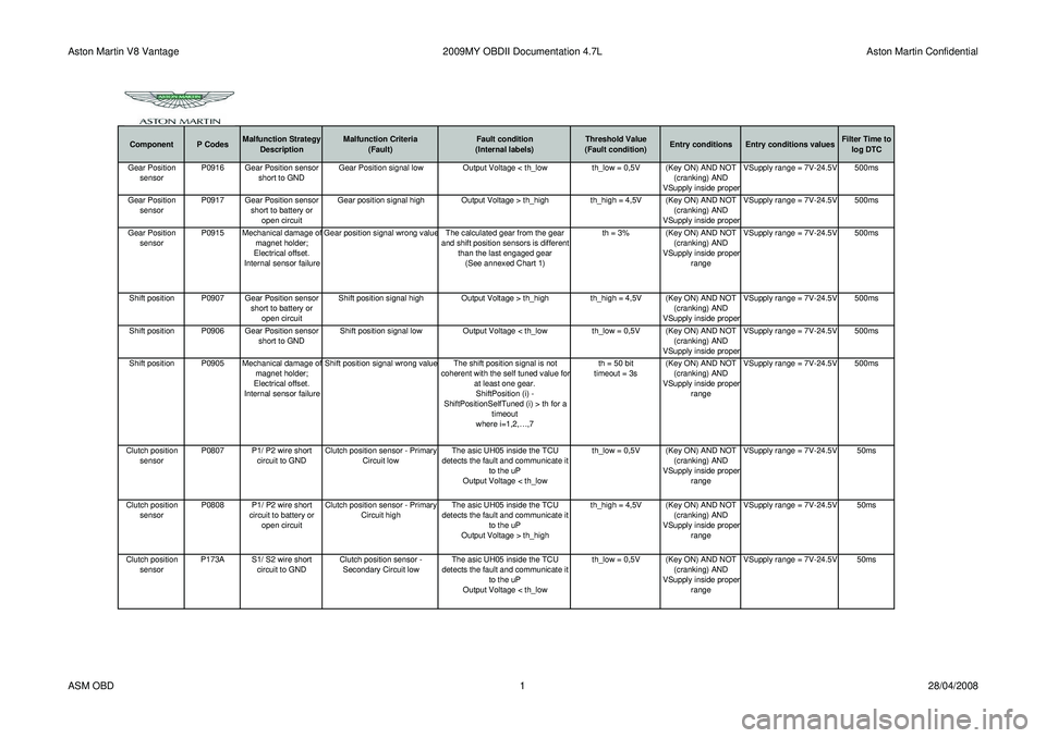
Component P CodesMalfunction Strategy
Description Malfunction Criteria
(Fault) Fault condition
(Internal labels) Threshold Value
(Fault condition) Entry conditions Entry conditions values Filter Time to
log DTC
Gear Position sensor P0916 Gear Position sensor
short to GND Gear Position signal low Output Voltage < th_low th_low = 0,5V (Key ON) AND NOT
(cranking) AND
VSupply inside prope
r VSupply range = 7V-24.5V 500ms
Gear Position sensor P0917 Gear Position sensor
short to battery or open circuit Gear position signal high Output Voltage > th_high
th_high = 4,5V (Key ON) AND NOT
(cranking) AND
VSupply inside proper VSupply range = 7V-24.5V 500ms
Gear Position sensor P0915 Mechanical damage o
f
magnet holder;
Electrical offset.
Internal sensor failure Gear position signal wrong value The calculated gear from the gear
and shift position sensors is different than the last engaged gear(See annexed Chart 1) th = 3% (Key ON) AND NOT
(cranking) AND
VSupply inside prope
r
range VSupply range = 7V-24.5V 500ms
Shift position P0907 Gear Position sensor short to battery or open circuit Shift position signal high Output Voltage > th_high
th_high = 4,5V (Key ON) AND NOT
(cranking) AND
VSupply inside proper VSupply range = 7V-24.5V 500ms
Shift position P0906 Gear Position sensor short to GNDShift position signal low
Output Voltage < th_low th_low = 0,5V (Key ON) AND NOT
(cranking) AND
VSupply inside proper VSupply range = 7V-24.5V 500ms
Shift position P0905 Mechanical damage o
f
magnet holder;
Electrical offset.
Internal sensor failure Shift position signal wrong value The shift position signal is not
coherent with the self tuned value fo
r
at least one gear.ShiftPosition (i) -
ShiftPositionSelfTuned (i) > th for a timeout
where i=1,2,…,7 th = 50 bit
timeout = 3s (Key ON) AND NOT
(cranking) AND
VSupply inside prope
r
range VSupply range = 7V-24.5V 500ms
Clutch position sensor P0807 P1/ P2 wire short
circuit to GND Clutch position sensor - Primary
Circuit low The asic UH05 inside the TCU
detects the fault and communicate it to the uP
Output Voltage < th_low th_low = 0,5V (Key ON) AND NOT
(cranking) AND
VSupply inside proper
range VSupply range = 7V-24.5V 50ms
Clutch position sensor P0808 P1/ P2 wire short
circuit to battery or open circuit Clutch position sensor - Primary
Circuit high The asic UH05 inside the TCU
detects the fault and communicate it to the uP
Output Voltage > th_high th_high = 4,5V (Key ON) AND NOT
(cranking) AND
VSupply inside proper
range VSupply range = 7V-24.5V 50ms
Clutch position sensor P173A S1/ S2 wire short
circuit to GND Clutch position sensor -
Secondary Circuit low The asic UH05 inside the TCU
detects the fault and communicate it to the uP
Output Voltage < th_low th_low = 0,5V (Key ON) AND NOT
(cranking) AND
VSupply inside proper
range VSupply range = 7V-24.5V 50ms
ASM OBD
128/04/2008
Page 906 of 947
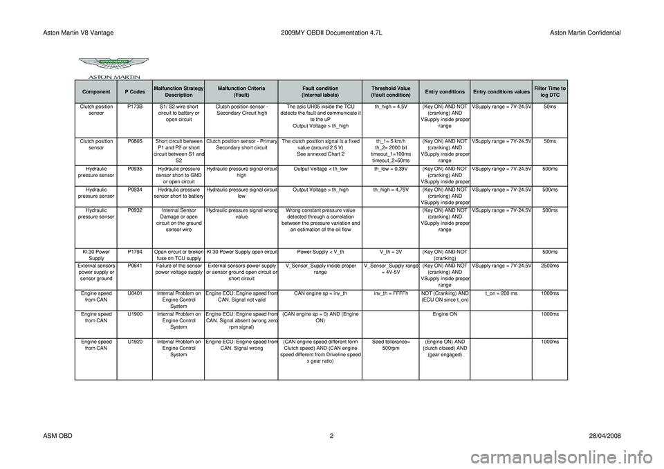
Aston Martin V8 Vantage2009MY OBDII Documentation 4.7L Aston Martin Confidential
Component P CodesMalfunction Strategy
Description Malfunction Criteria
(Fault) Fault condition
(Internal labels) Threshold Value
(Fault condition) Entry conditions Entry conditions values Filter Time to
log DTCClutch position sensor P173B S1/ S2 wire short
circuit to battery or open circuit Clutch position sensor -
Secondary Circuit high The asic UH05 inside the TCU
detects the fault and communicate it to the uP
Output Voltage > th_high th_high = 4,5V (Key ON) AND NOT
(cranking) AND
VSupply inside prope
r
range VSupply range = 7V-24.5V 50ms
Clutch position sensor P0805 Short circuit between
P1 and P2 or short
circuit between S1 and S2 Clutch position sensor - Primary
Secondary short circuit The clutch position signal is a fixed
value (around 2.5 V)
See annexed Chart 2 th_1= 5 km/h
th_2= 2000 bit
timeout_1=100ms timeout_2=50ms (Key ON) AND NOT
(cranking) AND
VSupply inside proper
range VSupply range = 7V-24.5V 50ms
Hydraulic
pressure sensor P0935 Hydraulic pressure
sensor short to GND or open circuit Hydraulic pressure signal circuit
high Output Voltage < th_low th_low = 0,39V (Key ON) AND NOT
(cranking) AND
VSupply inside proper VSupply range = 7V-24.5V 500ms
Hydraulic
pressure sensor P0934 Hydraulic pressure
sensor short to battery Hydraulic pressure signal circuit
low Output Voltage > th_high th_high = 4,79V (Key ON) AND NOT
(cranking) AND
VSupply inside proper VSupply range = 7V-24.5V 500ms
Hydraulic
pressure sensor P0932 Internal Sensor
Damage or open
circuit on the ground sensor wire Hydraulic pressure signal wrong
value Wrong constant pressure value
detected through a correlation
between the pressure variation and an estimation of the oil flow (Key ON) AND NOT
(cranking) AND
VSupply inside proper
range VSupply range = 7V-24.5V 500ms
Kl.30 Power Supply P1794 Open circuit or broken
fuse on TCU supply Kl.30 Power Supply open circuit Power Supply < V_th
V_th = 3V (Key ON) AND NOT
(cranking) 500ms
External sensors power supply or sensor ground P0641 Failure of the sensor
power voltage supply External sensors power supply
or sensor ground open circuit or short circuit V_Sensor_Supply inside proper
range V_Sensor_Supply range
= 4V-5V (Key ON) AND NOT
(cranking) AND
VSupply inside proper
range VSupply range = 7V-24.5V 2500ms
Engine speed from CAN U0401 Internal Problem on
Engine Control System Engine ECU: Engine speed fro
m
CAN. Signal not valid
CAN engine sp = inv_th inv_th = FFFFh NOT (Cranking) AND
(ECU ON since t_on)t_on = 200 ms 1000ms
Engine speed from CAN U1900 Internal Problem on
Engine Control System Engine ECU: Engine speed fro
m
CAN. Signal absent (wrong zero
rpm signal) (CAN engine sp = 0) AND (Engine
ON) Engine ON 1000ms
Engine speed from CAN U1920 Internal Problem on
Engine Control System Engine ECU: Engine speed fro
m
CAN. Signal wrong
(CAN engine speed different form
Clutch speed) AND (CAN engine
speed different from Driveline speed x gear ratio) Seed tollerance=
500rpm (Engine ON) AND
(clutch closed) AND (gear engaged) 1000ms
ASM OBD
228/04/2008
Page 907 of 947
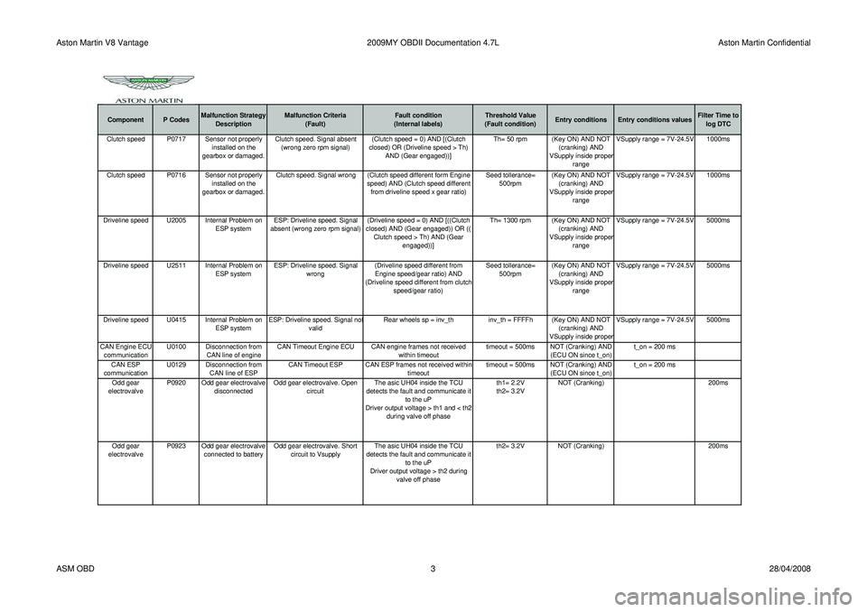
Aston Martin V8 Vantage2009MY OBDII Documentation 4.7L Aston Martin Confidential
Component P CodesMalfunction Strategy
Description Malfunction Criteria
(Fault) Fault condition
(Internal labels) Threshold Value
(Fault condition) Entry conditions Entry conditions values Filter Time to
log DTCClutch speed P0717 Sensor not properly installed on the
gearbox or damaged. Clutch speed. Signal absent
(wrong zero rpm signal) (Clutch speed = 0) AND [(Clutch
closed) OR (Driveline speed > Th) AND (Gear engaged))] Th= 50 rpm (Key ON) AND NOT
(cranking) AND
VSupply inside prope
r
range VSupply range = 7V-24.5V 1000ms
Clutch speed P0716 Sensor not properly installed on the
gearbox or damaged. Clutch speed. Signal wrong (Clutch speed different form Engine
speed) AND (Clutch speed different from driveline speed x gear ratio) Seed tollerance=
500rpm (Key ON) AND NOT
(cranking) AND
VSupply inside proper
range VSupply range = 7V-24.5V 1000ms
Driveline speed U2005 Internal Problem on ESP systemESP: Driveline speed. Signal
absent (wrong zero rpm signal) (Driveline speed = 0) AND [((Clutch
closed) AND (Gear engaged)) OR (( Clutch speed > Th) AND (Gear engaged))] Th= 1300 rpm (Key ON) AND NOT
(cranking) AND
VSupply inside proper
range VSupply range = 7V-24.5V 5000ms
Driveline speed U2511 Internal Problem on ESP systemESP: Driveline speed. Signal
wrong (Driveline speed different from
Engine speed/gear ratio) AND
(Driveline speed different from clutch speed/gear ratio) Seed tollerance=
500rpm (Key ON) AND NOT
(cranking) AND
VSupply inside proper
range VSupply range = 7V-24.5V 5000ms
Driveline speed U0415 Internal Problem on ESP systemESP: Driveline speed. Signal no
t
valid Rear wheels sp = inv_th
inv_th = FFFFh (Key ON) AND NOT
(cranking) AND
VSupply inside prope
r VSupply range = 7V-24.5V 5000ms
CAN Engine ECU communication U0100 Disconnection from
CAN line of engine CAN Timeout Engine ECU CAN engine frames not received
within timeouttimeout = 500ms NOT (Cranking) AND
(ECU ON since t_on) t_on = 200 ms
CAN ESP
communication U0129 Disconnection from
CAN line of ESP CAN Timeout ESP CAN ESP frames not received within
timeouttimeout = 500ms NOT (Cranking) AND
(ECU ON since t_on) t_on = 200 ms
Odd gear
electrovalve P0920 Odd gear electrovalve
disconnected Odd gear electrovalve. Open
circuit The asic UH04 inside the TCU
detects the fault and communicate it to the uP
Driver output voltage > th1 and < th2 during valve off phase th1= 2.2V
th2= 3.2V
NOT (Cranking)
200ms
Odd gear
electrovalve P0923 Odd gear electrovalve
connected to battery Odd gear electrovalve. Short
circuit to Vsupply The asic UH04 inside the TCU
detects the fault and communicate it to the uP
Driver output voltage > th2 during valve off phase th2= 3.2V
NOT (Cranking) 200ms
ASM OBD 328/04/2008
Page 908 of 947
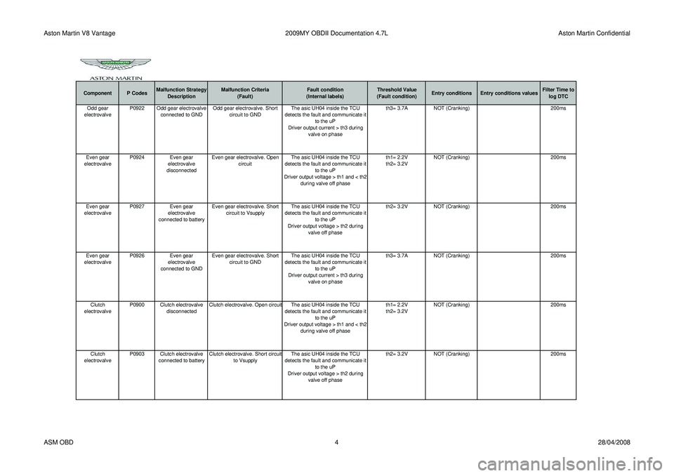
Aston Martin V8 Vantage2009MY OBDII Documentation 4.7L Aston Martin Confidential
Component P CodesMalfunction Strategy
Description Malfunction Criteria
(Fault) Fault condition
(Internal labels) Threshold Value
(Fault condition) Entry conditions Entry conditions values Filter Time to
log DTCOdd gear
electrovalve P0922 Odd gear electrovalve
connected to GND Odd gear electrovalve. Short
circuit to GND The asic UH04 inside the TCU
detects the fault and communicate it to the uP
Driver output current > th3 during valve on phase th3= 3.7A
NOT (Cranking) 200ms
Even gear
electrovalve P0924 Even gear
electrovalve
disconnected Even gear electrovalve. Open
circuit The asic UH04 inside the TCU
detects the fault and communicate it to the uP
Driver output voltage > th1 and < th2 during valve off phase th1= 2.2V
th2= 3.2V
NOT (Cranking)
200ms
Even gear
electrovalve P0927
Even gear
electrovalve
connected to battery Even gear electrovalve. Short
circuit to Vsupply The asic UH04 inside the TCU
detects the fault and communicate it to the uP
Driver output voltage > th2 during valve off phase th2= 3.2V
NOT (Cranking) 200ms
Even gear
electrovalve P0926 Even gear
electrovalve
connected to GND Even gear electrovalve. Short
circuit to GND The asic UH04 inside the TCU
detects the fault and communicate it to the uP
Driver output current > th3 during valve on phase th3= 3.7A
NOT (Cranking) 200ms
Clutch
electrovalve P0900 Clutch electrovalve
disconnected Clutch electrovalve. Open circuit The asic UH04 inside the TCU
detects the fault and communicate it to the uP
Driver output voltage > th1 and < th2 during valve off phase th1= 2.2V
th2= 3.2V
NOT (Cranking)
200ms
Clutch
electrovalve P0903 Clutch electrovalve
connected to battery Clutch electrovalve. Short circuit
to Vsupply The asic UH04 inside the TCU
detects the fault and communicate it to the uP
Driver output voltage > th2 during valve off phase th2= 3.2V
NOT (Cranking) 200ms
ASM OBD 428/04/2008
Page 909 of 947
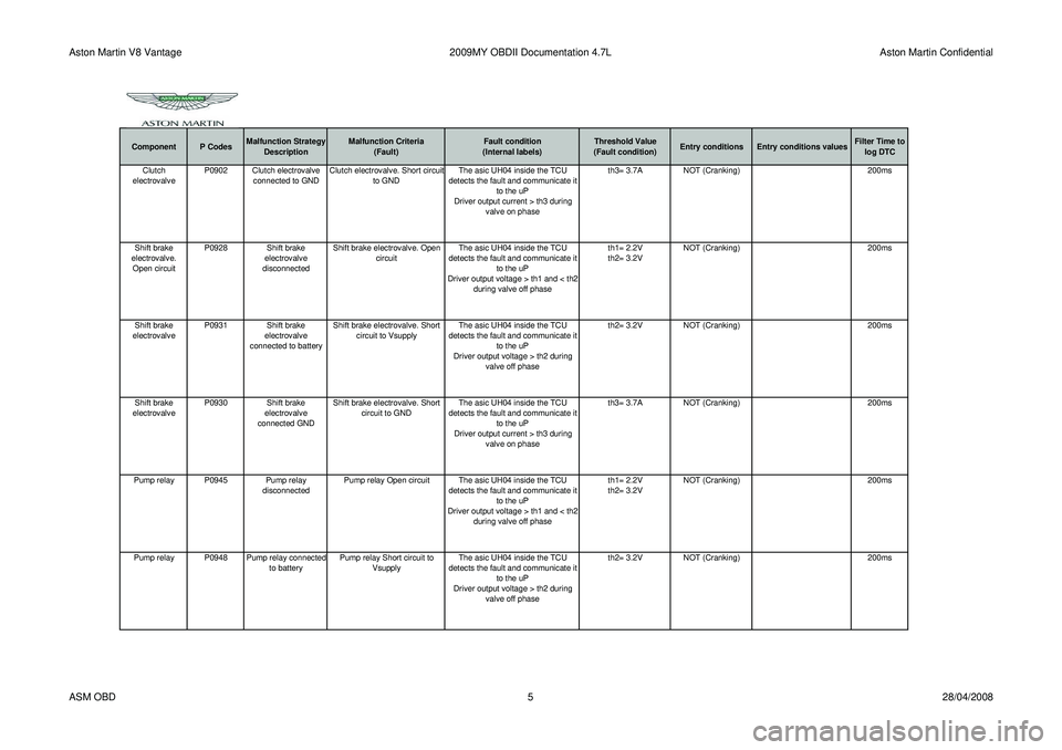
Aston Martin V8 Vantage2009MY OBDII Documentation 4.7L Aston Martin Confidential
Component P CodesMalfunction Strategy
Description Malfunction Criteria
(Fault) Fault condition
(Internal labels) Threshold Value
(Fault condition) Entry conditions Entry conditions values Filter Time to
log DTCClutch
electrovalve P0902 Clutch electrovalve
connected to GND Clutch electrovalve. Short circuit
to GND The asic UH04 inside the TCU
detects the fault and communicate it to the uP
Driver output current > th3 during valve on phase th3= 3.7A
NOT (Cranking) 200ms
Shift brake
electrovalve. Open circuit P0928 Shift brake
electrovalve
disconnected Shift brake electrovalve. Open
circuit The asic UH04 inside the TCU
detects the fault and communicate it to the uP
Driver output voltage > th1 and < th2 during valve off phase th1= 2.2V
th2= 3.2V
NOT (Cranking)
200ms
Shift brake
electrovalve P0931 Shift brake
electrovalve
connected to battery Shift brake electrovalve. Short
circuit to Vsupply The asic UH04 inside the TCU
detects the fault and communicate it to the uP
Driver output voltage > th2 during valve off phase th2= 3.2V
NOT (Cranking) 200ms
Shift brake
electrovalve P0930 Shift brake
electrovalve
connected GND Shift brake electrovalve. Short
circuit to GND The asic UH04 inside the TCU
detects the fault and communicate it to the uP
Driver output current > th3 during valve on phase th3= 3.7A
NOT (Cranking) 200ms
Pump relay P0945 Pump relay disconnectedPump relay Open circuit The asic UH04 inside the TCU
detects the fault and communicate it to the uP
Driver output voltage > th1 and < th2 during valve off phase th1= 2.2V
th2= 3.2V
NOT (Cranking)
200ms
Pump relay P0948 Pump relay connected to batteryPump relay Short circuit to
Vsupply The asic UH04 inside the TCU
detects the fault and communicate it to the uP
Driver output voltage > th2 during valve off phase th2= 3.2V
NOT (Cranking) 200ms
ASM OBD 528/04/2008
Page 933 of 947
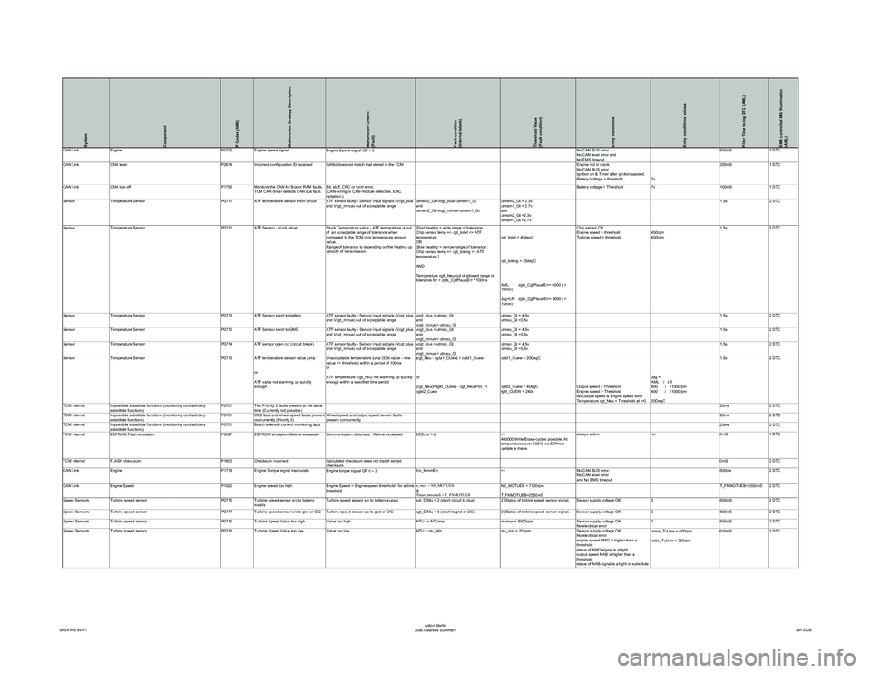
System
Component
P Codes (AML)
Malfunction Strategy Description
Malfunction Criteria
(Fault)
Fault condition
(Internal labels)
Threshold Value
(Fault condition)
Entry conditions
Entry conditions values
Filter Time to log DTC (AML)
EMS controlled MIL Illumination
(AML)
CAN LinkEngine P0725Engine speed signal
Engine Speed signal QF ≠ 3 No CAN BUS error.
No CAN level error and
No EMS timeout.600mS
1 DTC
CAN Link CAN level P0614Incorrect configuration ID received CANid does not match that stored in the TCM Engine not in crank.
No CAN BUS error
Ignition on & Timer after ignition passed.
Battery Voltage > threshold7v250mS
1 DTC
CAN Link CAN bus off P1796Monitors the CAN for Bus or RAM faults.
TCM CAN driver detects CAN bus fault. Bit, stuff, CRC or form error,
(CAN-wiring or CAN-module defective, EMC
radiation.) Battery voltage > Threshold
7v100mS1 DTC
Sensor Temperature Sensor P0711 ATF temperature sensor short circuit ATF sensor faulty - Sensor input signals (Vcgt_plus
and Vcgt_minus) out of acceptable range utmsm2_Gt
utmsm2_Gt
and
utmsm2_Gt =2.3v
utmsm1_Gt =2.7v 1.5s
2 DTC
Sensor Temperature Sensor P0711ATF Sensor - stuck value Stuck Temperature value - ATF temperature is out
of an acceptable range of tolerance when
compared to the TCM chip temperature sensor
value.
Range of tolerance is depending on the heating up
velocity of transmission . [
Fast heating = wide range of tolerance :
Chip sensor temp +/- cgt_tolwt <> ATF
temperature
OR
Slow heating = narrow range of tolerance :
Chip sensor temp +/- cgt_toleng <> ATF
temperature.]
AND
Temperature cgtf_Neu out of allowed range of
tolerance for > zgts_CgtPlausiErr * 100ms cgt_tolwt = 40degC
cgt_toleng = 25degC
AML: zgts_CgtPlausiErr= 6000 ( =
10min)
Jag+LR: zgts_CgtPlausiErr= 9000 ( =
15min)Chip sensor OK
Engine speed > threshold
Turbine speed > threshold
450rpm
450rpm1.5s
2 DTC
Sensor Temperature Sensor P0713ATF Sensor short to battery ATF sensor faulty - Sensor input signals (Vcgt_plus
and Vcgt_minus) out of acceptable range vcgt_plus > utmso_Gt
and
vcgt_minus > utmsu_Gtutmso_Gt = 4.5v
utmsu_Gt =0.5v
1.5s
2 DTC
Sensor Temperature Sensor P0712ATF Sensor short to GND ATF sensor faulty - Sensor input signals (Vcgt_plus
and Vcgt_minus) out of acceptable range vcgt_plus < utmso_Gt
and
vcgt_minus < utmsu_Gtutmso_Gt = 4.5v
utmsu_Gt =0.5v
1.5s
2 DTC
Sensor Temperature Sensor P0714ATF sensor open cct (circuit break) ATF sensor faulty - Sensor input signals (Vcgt_plus
and Vcgt_minus) out of acceptable range vcgt_plus > utmso_Gt
and
vcgt_minus < utmsu_Gtutmso_Gt = 4.5v
utmsu_Gt =0.5v
1.5s
2 DTC
Sensor Temperature Sensor P0713 ATF temperature sensor value jump
or
ATF value not warming up quickly
enough Unacceptable temperature jump (lOld value - new
value <> threshold) within a period of 100ms
or
ATF temperature (cgt_neu) not warming up quickly
enough within a specified time period
|cgt_Neu - cgta1_CUew| > cgtd1_Cuew
or
(cgt_Neu(t=tgtd_CUew) - cgt_Neu(t=0) ) <
cgtd2_Cuewcgtd1_Cuew = 20DegC
cgtd2_Cuew = 4DegC
tgtd_CUEW = 240s
Output speed > Threshold
Engine speed > Threshold
No Output speed & Engine speed error
Temperature cgt_Neu < Threshold at t=0Jag +
AML / LR
800 / 11000rpm
400 / 11000rpm
20DegC1.5s
2 DTC
TCM Internal Impossible substitute functions (monitoring contradictory
substitute functions) P0701
Two Priority 2 faults present at the same
time (Currently not possible) 20ms
2 DTC
TCM Internal Impossible substitute functions (monitoring contradictory
substitute functions) P0701
OSS fault and wheel speed faults present
concurrently (Priority 3) Wheel speed and output speed sensor faults
present concurrently. 20ms
2 DTC
TCM Internal Impossible substitute functions (monitoring contradictory
substitute functions) P0701
Bosch solenoid current monitorin
g fault 20ms 2 DTC
TCM Internal EEPROM Flash emulation P062FEEPROM emulation lifetime exceeded Communication disturbed, lifetime exceeded EEError !=0 =1
400000 Write/Erase-cycles possible. At
temperatures over 135°C no EEProm
update is made.always active
no0mS1 DTC
TCM Internal FLASH checksum P1603Checksum incorrect Calculated checksum does not match stored
checksum 0mS
2 DTC
CAN Link Engine P1719Engine Torque signal inaccurate
Engine torque signal QF 0 = 3 fcn_MmmErr
=1No CAN BUS error.
No CAN level error
and No EMS timeout. 600ms
2 DTC
CAN Link Engine Speed P1920Engine speed too high Engine Speed > Engine speed threshold> for a time
threshold n_mot > NS_MOTUEB
&
Timer_nmotueb > T_FNMOTUEBNS_MOTUEB = 7100rpm
T_FNMOTUEB=2550mS T_FNMOTUEB=2550mS 2 DTC
Speed Sensors Turbine speed sensor P0715Turbine speed sensor s/c to battery
supply Turbine speed sensor s/c to battery supply sgt_DiNtu = 2 (short circuit to plus)
2 (Status of turbine speed sensor signal. Sensor supply voltage OK0600mS2 DTC
Speed Sensors Turbine speed sensor P0717Turbine speed sensor s/c to gnd or O/C Turbine speed sensor s/c to gnd or O/C sgt_DiNtu = 0 (short to gnd or OC)0 (Status of turbine speed sensor signal. Sensor supply voltage OK 0600mS2 DTC
Speed Sensors Turbine speed sensor P0716Turbine Speed Value too high Value too high NTU >= NTUmaxntumax = 8000rpmSensor supply voltage OK
No electrical error 0
600mS2 DTC
Speed Sensors Turbine speed sensor P0716Turbine Speed Value too low Value too low NTU < ntu_Minntu_min = 20 rpmSensor supply voltage OK
No electrical error
engine speed NMO is higher than a
threshold:
status of NMO-signal is alright
output speed NAB is higher than a
threshold:
status of NAB-signal is alright or substitute
fltfl fb Ei t t
nmos_TuUew = 600rpm
nabs_TuUew = 250rpm 600mS
2 DTC
8ASXV05.9VH1 Aston Martin
Auto Gearbox Summary Jan 2008
Page 934 of 947
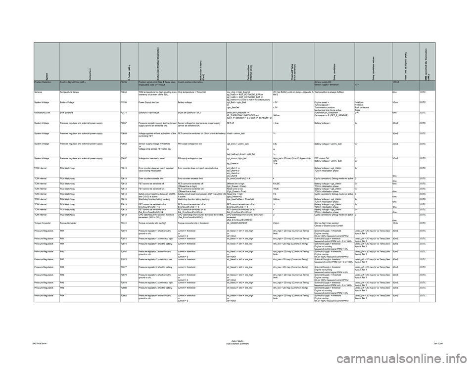
System
Component
P Codes (AML)
Malfunction Strategy Description
Malfunction Criteria
(Fault)
Fault condition
(Internal labels)
Threshold Value
(Fault condition)
Entry conditions
Entry conditions values
Filter Time to log DTC (AML)
EMS controlled MIL Illumination
(AML)
y volts Vs temp - Appendix A,
Ref 2 Test condition is always fulfilled. 0ms 1 DTC
System Voltage Battery Voltage P1793 Power Supply too low Battery voltage ugt_Batt < ugtu_Batt or
ugtu_BattDef< 7V
< 7VEngine speed >
Turbine speed >
Transmission position
Mechanical limp home active1400rpm
1400rpm
Park or Neutral
False30ms
2 DTC
Mechatronic Unit Shift Solenoid P0771Solenoid / Valve stuck Stuck off Solenoid 1 or 2 timer_MV12mechdef <=
KL_TUEBCGMV12MECHDEF and
(GET_P_SENSOR = 0 or GET_P_SENSOR = 2) 500mspumpendruck_vorhanden
Park sensor = P (GET_P_SENSOR)0->1
0ms2 DTC
System Voltage Pressure regulator and solenoid power supply P0657Pressure regulator supply too low (power
supply cannot be switched on) Sensor voltage too low because power supply
cannot be switched ON. FET off
= trueBattery Voltage > 7v30mS2 DTC
System Voltage Pressure regulator and solenoid power supply P0659Voltage applied without activation of the
controlling FET FET cannot be switched on (Short circuit to battery) Vbatt > udrmv_batt
7v 30mS2 DTC
System Voltage Pressure regulator and solenoid power supply P0658Sensor supply voltage < threshold
or
Voltage drop across FET is too big PR supply voltage too low
u
gt_drmv < udrmv_ksm
or
lugt_batt-ugt_drmvl > ugtd_fet 0.5v
or
1vBattery Voltage > udrmv_batt
7v30mS2 DTC
System Voltage Pressure regulator and solenoid power supply P0657Voltage too low due to reset. PR supply voltage too low ugt_drmv < Ugtu_bat
fgt_Dreset = Ugtu_bat = 2D map (V vs C) Appendix A,
ref 3
TrueFET control OK
Battery Voltage > udrmv_batt
1
7v30mS
2 DTC
TCM Internal TCM Watchdog P0613Error counter does not reach required
value during initialisation Error counter does not reach required value sdi_Ufet=1 or
sdi_Ufet=4 or
sdi_Ufet=5 or
sdi_Ufet=8 Battery Voltage > ugt_UfetIni
TCU in initialisation phase
7v
0ms2 DTC
TCM Internal TCM Watchdog P0613Error counter exceeds limit Error counter exceeds limit Zs_errorCountForUC > 4.4Cyclic (operation): Debug-mode not active 0
0ms2 DTC
TCM Internal TCM Watchdog P0613FET cannot be switched off FET cannot be switched off
(DReset line is high) DReset line is high
(fgtr_Dreset = False)FALSE
Battery Voltage > ugt_UfetIni
TCU in initialisation phase7v
0ms2 DTC
TCM Internal TCM Watchdog P0613FET cannot be switched On FET cannot be switched On
(DReset line is low) Reset Line is low.
(Fgtr_Dreset = True)TRUE
Battery Voltage > ugt_UfetIni
TCU in initialisation phase7v
0ms2 DTC
TCM Internal TCM Watchdog P0613Safety circuit reset line between CG115
and CG120 is active. Safety circuit reset line between CG115 and CG120
is active. Reset line = high
(fgtr_Dreset!=0)!=0
Cyclic (operation): Debug-mode not active 0
0ms2 DTC
TCM Internal TCM Watchdog P0613Watchdog function taking too long. Watchdog function taking too long. tgts_UewFetGes > Threshold300msBattery Voltage > ugt_UfetIni
TCU in initialisation phase7v
0ms2 DTC
TCM Internal TCM Watchdog P0613FET cannot be switched off at
ErrorCountForUC >= 5 FET cannot be switched off at
ErrorCountForUC >= 5 FET cannot be switched off at
ErrorCountForUC >= 55
Battery Voltage > ugt_UfetIni
TCU in initialisation phase7v
0ms2 DTC
TCM Internal TCM Watchdog P0613FET cannot be switched on at
Zsk_ErrorCountForUC<=4 FET cannot be switched on at
Zsk_ErrorCountForUC<=4 FET cannot be switched on at
Zsk_ErrorCountForUC<=44
Battery Voltage > ugt_UfetIni
TCU in initialisation phase7v
0ms2 DTC
TCM Internal TCM Watchdog P0613CPU watchdog error counter threshold
exceeded. (WD to CPU) CPU watchdog error counter threshold exceeded.
(Zsk_ErrorCountForWD>3) CPU watchdog error counter threshold
exceeded.
(Zsk_ErrorCountForWD>3)3
Cyclic (operation): Debug-mode not active 0
0ms2 DTC
Torque Converter Torque Converter P0741Torque converter slip too high Torque converter slip > threshold. KL_NDSKPLDEFEKT25rpmSlip too high timer expired
Closed or Closed Loop Control 10.0s
2 DTC
Pressure Regulators PR1 P0973Pressure regulator 1 short circuit to
ground or o/c. current > threshold
or
current = 0 idr_Mess1 > idr1 + idrs_high
or
idr1=0mAidrs_high = 2D map (Current vs Temp)
0mA
Solenoid Supply > threshold
Engine running
0% or 100% measured current PWMudrso_prf = 2D map (V vs Temp) See
App A, Ref 1
30mS
2 DTC
Pressure Regulators PR1 P0972Pressure regulator 1 current too high current > threshold idr_Mess1 > idr1 + idrs_highidrs_high = 2D map (Current vs Temp) Solenoid Supply > threshold
Measured control PWM not = 0 or 100%udrso_prf = 2D map (V vs Temp) See
App A, Ref 130mS
2 DTC
Pressure Regulators PR1 P0974Pressure regulator 1 short to battery current < threshold idr_Mess1 < idr1 + idrs_lowidrs_low = 2D map (Current vs Temp) Solenoid Supply > threshold
Engine not running
Measured control signal PWM = 0%udrso_prf = 2D map (V vs Temp) See
App A, Ref 1
30mS
2 DTC
Pressure Regulators PR2 P0976Pressure regulator 2 short circuit to
ground or o/c. current > threshold
or
current = 0 idr_Mess2 > idr2 + idrs_high
or
idr1=0mAidrs_high = 2D map (Current vs Temp)
0mA
Solenoid Supply > threshold
Engine running
0% or 100% measured current PWMudrso_prf = 2D map (V vs Temp) See
App A, Ref 1
50mS
2 DTC
Pressure Regulators PR2 P0975Pressure regulator 2 current too low current < threshold idr_Mess2 < idr2 + idrs_lowidrs_low = 2D map (Current vs Temp) Solenoid Supply > threshold
Meassured control PWM not = 0 or 100%udrso_prf = 2D map (V vs Temp) See
App A, Ref 150mS
2 DTC
Pressure Regulators PR2 P0977Pressure regulator 2 short to battery current < threshold idr_Mess2 < idr2 + idrs_lowidrs_low = 2D map (Current vs Temp) Solenoid Supply > threshold
Engine not running
Measured control signal PWM = 0%udrso_prf = 2D map (V vs Temp) See
App A, Ref 1
50mS
2 DTC
Pressure Regulators PR3 P0979Pressure regulator 3 short circuit to
ground or o/c. current > threshold
or
current = 0 idr_Mess3 > idr3 + idrs_high
or
idr1=0mAidrs_high = 2D map (Current vs Temp)
0mA
Solenoid Supply > threshold
Engine running
0% or 100% measured current PWMudrso_prf = 2D map (V vs Temp) See
App A, Ref 1
50mS
2 DTC
Pressure Regulators PR3 P0978Pressure regulator 3 current too high current > threshold idr_Mess3 > idr3 + idrs_highidrs_high = 2D map (Current vs Temp) Solenoid Supply > threshold
Measured control PWM not = 0 or 100%udrso_prf = 2D map (V vs Temp) See
App A, Ref 150mS
2 DTC
Pressure Regulators PR3 P0980Pressure regulator 3 short to battery current < threshold idr_Mess3 < idr3 + idrs_lowidrs_low = 2D map (Current vs Temp) Solenoid Supply > threshold
Engine not running
Measured control signal PWM = 0%udrso_prf = 2D map (V vs Temp) See
App A, Ref 1
50mS
2 DTC
Pressure Regulators PR4 P0982Pressure regulator 4 short circuit to
ground or o/c. current > threshold
or
current = 0 idr_Mess4 > idr4 + idrs_high
or
idr1=0mAidrs_high = 2D map (Current vs Temp)
0mA
Solenoid Supply > threshold
Engine running
0% or 100% measured current PWMudrso_prf = 2D map (V vs Temp) See
App A, Ref 1
50mS
2 DTC
8ASXV05.9VH1 Aston Martin
Auto Gearbox Summary Jan 2008