fuel ASTON MARTIN V8 VANTAGE 2010 Owner's Guide
[x] Cancel search | Manufacturer: ASTON MARTIN, Model Year: 2010, Model line: V8 VANTAGE, Model: ASTON MARTIN V8 VANTAGE 2010Pages: 947, PDF Size: 43.21 MB
Page 312 of 947
Fuel Charging System (03.04)
Engine (03.00)3-4-6 Workshop Manual May 2007
Installation
1. Install new O-rings to remaining injectors (lube O-ringP-
clips).
2. Install clip to new injector then injector into rail.
3. Install rail (with injectors) to manifold (bolt x2) (torque)
(taking care each injector is aligned correctly).
4. Connect EGR vac pipe to sensor and manifold.
5. Install coolant pipe bracket (bolt x2, nut x2).
6. Connect EGR (x1), fuel rail pressure sensor (x1) and injector multiplugs (x4).
7. Refit harness to coolant pipe bracket (fir tree x3).
8. Connect heater hose to pipe (quick fit).
9. Refit heater hose (clipx2) and EGR vacuum lines (clips
x2) to bracket.
10. Install fuel feed pipe.
11. Install purge pipe P-clip.
12. Install harness bracket to engine.
13. Feed harness into inner wing area.
14. Install fusebox to bracket.
15. Install earth lead to fusebox.
16. Install battery lead to fusebox (1x nut and rubber cover).
17. Install multiplugs to fuse box.
18. Install fusebox bracket fixings.
19. Refit harness fir tree clips to cylinder head.
20. Refit engine breather hose.
21. Install VVT solenoid multiplug, position coil and CMP harness (1x edge clip).
22. Install ECM (see Workshop Manual procedure 03.14.BB Engine Control Module - RH Renew).
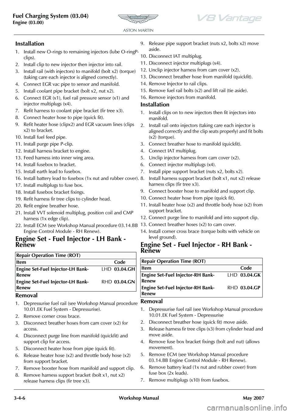
Engine Set - Fuel Injector - LH Bank -
Renew
Removal
1. Depressurise fuel rail (see Workshop Manual procedure 10.01.EK Fuel System - Depressurise).
2. Remove corner cross brace.
3. Disconnect breather hoses from cam cover (x2) for access.
4. Disconnect purge line from manifold (quickfit) and
support clip for access.
5. Disconnect heater hose from pipe (quick fit).
6. Release heater hose (x2) and throttle body hose (x2)
from support bracket.
7. Remove booster hose from manifold and support clip.
8. Remove harness support bracket (bolt x1, nut x2) release harness clips (fir tree x3). 9. Release pipe support bracket
(nuts x2, bolts x2) move
aside.
10. Disconnect IAT multiplug.
11. Disconnect injector multiplugs (x4).
12. Unclip injector harness from cam cover (x2).
13. Disconnect breather hose from manifold (quickfit).
14. Remove Injector to rail clips.
15. Remove fuel rail bolts (x2) and lift rail (tie aside).
16. Remove injectors from manifold.
Installation
1. Install clips on to new injectors then fit injectors into manifold.
2. Install rail onto injectors (taking care each injector is aligned correctly and the clip seats properly) and fit bolts
(x2) (torque).
3. Connect breather hose to manifold (quickfit).
4. Connect IAT multiplug.
5. Unclip injector harness from cam cover (x2).
6. Connect injector multiplugs (x4).
7. Install pipe support bracket (nuts x2, bolts x2).
8. Install harness support bracket (bolt x1, nut x2) release harness clips (fir tree x3).
9. Connect booster hose to manifold and support clip.
10. Connect heater hose from pipe (quick fit).
11. Install heater hose (x2) and throttle body hose (x2) from support bracket.
12. Connect purge line to manifold and into support clip.
13. Connect breather hoses (x2) to cam cover.
14. Install corner cross brace (torque bolts with vehicle on level ground).
Engine Set - Fuel Injector - RH Bank -
Renew
Removal
1. Depressurise fuel rail (see Workshop Manual procedure 10.01.EK Fuel System - Depressurise
2. Disconnect breather hose (quick fit) move aside.
3. Release harness fir tree clips (x3) from cylinder head and move aside.
4. Remove fuse box bracket fixings (bolt and nut) (allows movement).
5. Remove ECM (see Workshop Manual procedure 03.14.BB Engine Contro l Module - RH Renew).
6. Remove battery lead (1x nut and rubber cover) from fuse box (2x leads).
7. Remove multiplugs (x10) from fusebox.
Repair Operation Time (ROT)
Repair Operation Time (ROT)
ItemCode
Engine Set-Fuel Injector-RH Bank-
Renew LHD
03.04.GK
Engine Set-Fuel Injector-RH Bank-
Renew RHD
03.04.GP
Page 313 of 947

Fuel Charging System (03.04)
Engine (03.00)
May 2007 Workshop Manual 3-4-7
8. Remove earth terminal (1x nut and rubber cover) from
fusebox.
9. Remove fuse box from bracket (bolt x2).
10. Release harness fir tree clips (x3) from engine bracket.
11. Feed harness from inner wing and over engine to gain access to cam cover.
12. Remove purge pipe P-clip (bolt x1) and move pipe aside.
13. Remove harness bracket from engine (bolts x2, nut x1).
14. Release fuel feed hose from rail (clip x1) and move aside.
15. Disconnect heater hose from pipe (quick fit).
16. Release heater hose (clips x2) and EGR vacuum line (clips x2) from bracket.
17. Release harness from coolant pipe bracket (fir tree x3).
18. Disconnect EGR (x1), fuel ra il pressure sensor (x1) and
injector multiplugs (x 4), move harness aside.
19. Remove coolant pipe bracket (nuts x2 and bolts x2).
20. Disconnect EGR vac pipe from sensor and manifold,
move aside.
21. Remove Injector to rail clips.
22. Remove fuel rail bolts (x2) and lift rail (tie aside).
23. Remove injectors from manifold.
Installation
1. Install clips on to new injectors then fit injectors into manifold.
2. Install rail onto injectors (taking care each injector is aligned correctly and the clip seats properly) and fit bolts
(x2) (torque).
3. Connect EGR vac pipe to sensor and manifold.
4. Install coolant pipe bracket (bolt x2, nut x2).
5. Connect EGR (x1), fuel rail pressure sensor (x1) and
injector multiplugs (x4).
6. Refit harness to coolant pipe bracket (fir tree x3).
7. Connect heater hose to pipe (quick fit).
8. Refit heater hose (clipx2) and EGR vac lines (clips x2) to bracket.
9. Install fuel feed pipe.
10. Install purge pipe P-clip.
11. Install harness bracket to engine.
12. Feed harness into inner wing area.
13. Install fusebox to bracket.
14. Install earth lead to fusebox.
15. Install battery lead to fusebox (1x nut and rubber cover).
16. Install multiplugs to fuse box.
17. Install fusebox bracket fixings.
18. Refit harness fir tree clips to cylinder head.
19. Refit engine breather hose.
20. Install VVT solenoid multip lug, position coil and CMP
harness (1x edge clip).
21. Install ECM (see Workshop Manual procedure 03.14.BB Engine Control Module - RH Renew).
Page 314 of 947

Fuel Charging System (03.04)
Engine (03.00)3-4-8 Workshop Manual May 2007
Page 415 of 947
Evaporative Emissions (03.13)
Engine (03.00)
May 2007 Workshop Manual 3-13-1
Engine (03.00)
Evaporative Emissions (03.13)
Description
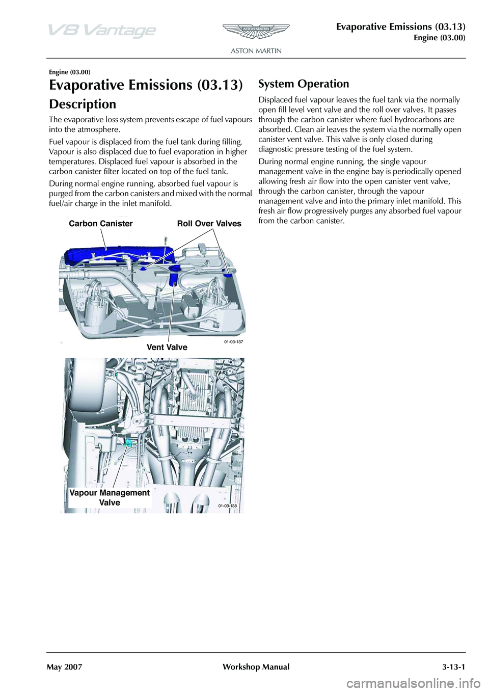
The evaporative loss system prevents escape of fuel vapours
into the atmosphere.
Fuel vapour is displaced from the fuel tank during filling.
Vapour is also displaced due to fuel evaporation in higher
temperatures. Displaced fuel vapour is absorbed in the
carbon canister filter located on top of the fuel tank.
During normal engine running, absorbed fuel vapour is
purged from the carbon canisters and mixed with the normal
fuel/air charge in the inlet manifold.
System Operation
Displaced fuel vapour leaves the fuel tank via the normally
open fill level vent valve and the roll over valves. It passes
through the carbon canister where fuel hydrocarbons are
absorbed. Clean air leaves the system via the normally open
canister vent valve. This valve is only closed during
diagnostic pressure testing of the fuel system.
During normal engine ru nning, the single vapour
management valve in the engine bay is periodically opened
allowing fresh air flow into th e open canister vent valve,
through the carbon canister, through the vapour
management valve and into the primary inlet manifold. This
fresh air flow progressively purg es any absorbed fuel vapour
from the carbon canister.
Page 426 of 947
Road Wheel Alignment (04.00)
Suspension (04.00)1-1-2 Workshop Manual Issue 6, May 2010
Suspension (04.00)
Road Wheel Alignment (04.00)
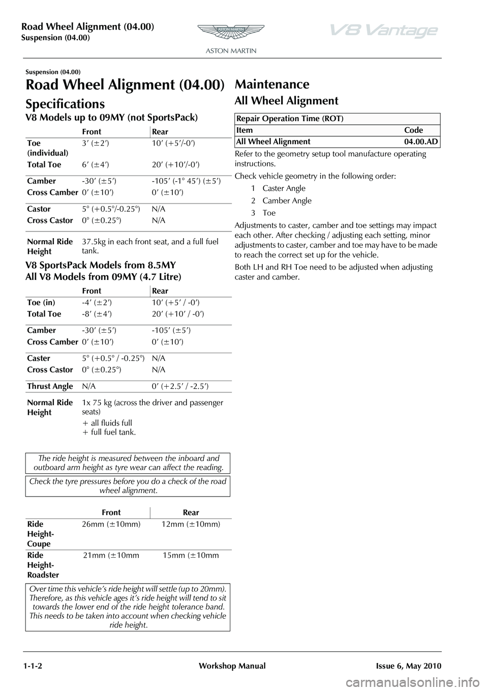
Specifications
V8 Models up to 09MY (not SportsPack)
V8 SportsPack Models from 8.5MY
All V8 Models from 09MY (4.7 Litre)
Maintenance
All Wheel Alignment
Refer to the geometry setup tool manufacture operating
instructions.
Check vehicle geometry in the following order:
1 Caster Angle
2 Camber Angle
3Toe
Adjustments to caster, camber and toe settings may impact
each other. After checking / adjusting each setting, minor
adjustments to caster, camber and toe may have to be made
to reach the correct set up for the vehicle.
Both LH and RH Toe need to be adjusted when adjusting
caster and camber.
Front Rear
Toe
(individual) 3’ (±2’) 10’ (+5’/-0’)
Total Toe 6’ (±4’) 20’ (+10’/-0’)
Camber -30’ (±5’) -105’ (-1° 45’) (±5’)
Cross Camber 0’ (±10’) 0’ (±10’)
Castor 5° (+0.5°/-0.25°) N/A
Cross Castor 0° (±0.25°) N/A
Normal Ride
Height 37.5kg in each front seat, and a full fuel
tank.
Front Rear
Toe (in) -4
Page 427 of 947

Front Suspension (04.01)
Suspension (04.00)
November 2008 Workshop Manual 4-1-1
Suspension (04.00)
Front Suspension (04.01)
Description
Suspension Arms
The upper suspension arm is attached to the body structure.
The lower suspension arm is attached to the front subframe.
Each upper suspension arm has a press-fit ball-joint, and two
interleaved rubber bushes. Two bolts attach the upper
suspension arm to the body structure.
Each lower suspension arm has a press fit ball-joint and
metal-to-rubber bonded bushes which are attached to the
front subframe by two eccentric cam bolts (Camber and
castor settings).
Anti-roll Bar
The anti-roll bar, is attached to the subframe in two positions
by rubber bushes and clamps. The outer ends of the anti-roll
bar are attached to the lower suspension arms by drop links.
The anti-roll bar provides the required stiffness to control
body roll.
Vertical link
The Vertical link (Knuckle Joint) swivels on the upper and
lower suspension arms via ball-joints, and carries the hub, a
unit 3 wheel bearing (including the ABS encoder ring), the
wheel speed sensor, the brake caliper, and the brake disc
and shield. The position of the Vertical link is determined by
the movement of the steering rack, which is connected to
the Vertical link by the steering track rod.
Specifications
Upper Arm Ball Joint
and Bushes
Ball Joint
and Bushes Verticle
Link
Bolts to Body
Lower Arm
Anti-roll Bar Drop Links
Eccentric
Cam Bolts
04-01-003
Torque Figures
DescriptionNmlb. / ft.
Brake dust shield. 9 7
Bearing Assembly to the Vertical
link. 55 41
Vertical Link to the Lower
Suspension Arm. 90 66.5
Vertical Link to the Upper
Suspension Arm. 90 66.5
Track-rod End Lock Nut. 70 52
Vehicle Ride Height Sensor. M8 M522.5
9 17
7
Anti-roll Bar Link Nuts 110 81.5
Anti-roll Bar Mounting Bolts
Torque bolt 1, then bolt 2, then
bolt 1 again (to allow for rubber
compression) 22.5 17
Torque the following suspensi on fixings with the vehicle
at normal ride height
Lower Suspension Arm front
bush to the Subframe M14 185 137
Lower Suspension Arm rear
bush to the Subframe. M12 115 85
Upper Suspension Arm to the
Front Structure 115 85
Spring and Damper Bolts Top Lower22.5
175 17
129.5
Normal ride height 2 x 37.5kg in front seats (37.5kg in
each seat) plus a full fuel tank.
Page 436 of 947
Rear Suspension (04.02)
Suspension (04.00)4-2-2 Workshop Manual May 2007
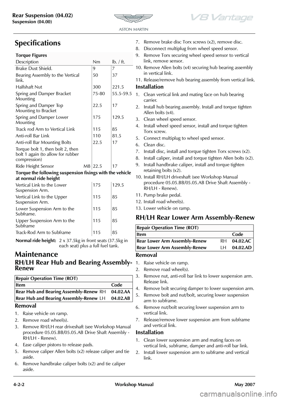
Specifications
Maintenance
RH/LH Rear Hub and Bearing Assembly-
Renew
Removal
1. Raise vehicle on ramp.
2. Remove road wheel(s).
3. Remove RH/LH rear drivesha ft (see Workshop Manual
procedure 05.05.BB/05.05.AB Drive Shaft Assembly -
RH/LH - Renew).
4. Ease caliper pistons to release pads.
5. Remove caliper Allen bolts (x2) release caliper and tie aside.
6. Remove handbrake caliper bolts (x2) and tie caliper aside. 7. Remove brake disc Torx screws (x2), remove disc.
8. Disconnect multiplug fr
om wheel speed sensor.
9. Remove Torx securing wheel speed sensor to vertical link, remove sensor.
10. Remove Allen bolts (x4) se curing hub bearing assembly
in vertical link.
11. Release/remove hub bearing a ssembly from vertical link.
Installation
1. Clean vertical link and mating face on hub bearing
carrier.
2. Install hub bearing assembly. Install and torque tighten Allen bolts (x4).
3. Clean wheel speed sensor.
4. Install wheel speed sensor, install and torque tighten Torx screw.
5. Connect multiplug to wheel sped sensor.
6. Clean disc.
7. Install disc, install and torq ue tighten Torx screws (x2).
8. Install caliper, install and torque tighten Allen bolts (x2).
9. Install handbrake caliper, install and torque tighten
retaining bolts (x2).
10. Install RH/LH driveshaft (see Workshop Manual
procedure 05.05.BB/05.05.AB Drive Shaft Assembly -
RH/LH - Renew).
11. Pump brake pedal.
12. Install road wheel(s).
13. Lower vehicle on ramp.
RH/LH Rear Lower Arm Assembly-Renew
Removal
1. Raise vehicle on ramp.
2. Remove road wheel(s).
3. Remove nut, anti-roll bar li nk to lower suspension arm.
Release link.
4. Remove bolt securing damper to lower suspension arm.
5. Remove bolt and nut/bolt, securing lower suspension arm to subframe.
6. Remove nut/bolt securing lower suspension arm to
vertical link.
7. Release/remove lower suspension arm from subframe and vertical link.
Installation
1. Clean lower suspension arm and mating faces on vertical link, subframe, damper and anti-roll bar link.
2. Install lower suspension ar m to subframe and vertical
link.
Torque Figures
DescriptionNmlb. / ft.
Brake Dust Shield. 9 7
Bearing Assembly to the Vertical
link. 50 37
Halfshaft Nut 300 221.5
Spring and Damper Bracket
Mounting 75-80 55.5-59.5
Spring and Damper Top
Mounting to Bracket 22.5 17
Spring and Damper Lower
Mounting 175 129.5
Track rod Arm to Vertical Link 115 85
Anti-roll Bar Link 110 81.5
Anti-roll Bar Mounting Bolts
Torque bolt 1, then bolt 2, then
bolt 1 again (to allow for rubber
compression) 22.5 17
Ride Height Sensor M8 22.5 17
Torque the following suspensi on fixings with the vehicle
at normal ride height
Vertical Link to the Lower
Suspension Arm. 175 129.5
Vertical Link to the Upper
Suspension Arm. 115 85
Lower Suspension Arm to the
Subframe. 115 85
Upper Suspension Arm to the
Subframe 115 85
Track-Rod Arm to Subframe 115 85
Normal ride height: 2 x 37.5kg in front seats (37.5kg in
each seat) plus a full fuel tank.
Repair Operation Time (ROT)
Repair Operation Time (ROT)
ItemCode
Rear Lower Arm Assembly-Renew RH04.02.AC
Rear Lower Arm Assembly-Renew LH04.02.AD
Page 445 of 947

Shock Absorber System (04.03)
Suspension (04.00)
May 2007 Workshop Manual 4-3-5
7. Remove nuts (x3 each side) from damper top mounting and remove engine cross brace support.
8. Remove nuts and bolts each side from damper lower mountings.
9. Remove spring and damper assembly.
10. Position spring compresso r to spring and compress
spring.
11. Hold damper shaft, and remove top mounting retaining nut.
12. Remove top mounting and spring assembly.
13. Remove dust shield from rebound bumper and spring seat flange.
Installation
1. Clean spring , spring seat flange, bumper, dust shield and top mounting .
2. Install spring seat flange, rebound bumper and dust shield onto damper.
3. Install spring and top mounting and install and tighten retaining nut.
4. Remove spring compressor.
5. Install spring and damper assembly and install engine cross brace support.
6. Install top mounting nuts (x3) each side (do not torque tighten).
7. Align damper to lower mounting and install bolts and nuts each side (do not torque tighten).
8. Position upper suspension arm and install bolts and nuts (x2) each side (do not torque tighten).
9. Connect ABS sensor multiplug and install harness clips in upper suspension arm and vertical link.
10. Install road wheel(s).
11. Lower vehicle on ramp.
12. Tighten upper arm nuts an d bolts to correct torque.
13. Torque tighten top mounting nuts (x3) and lower mounting nut and bolt.
14. Align engine cross brace, install Torx bolts (x2) and
tighten Torx bolts (x4) to correct torque.
Rear Spring and Damper Assembly-Pair-
Renew
Removal
1. Open fuel filler lid and remove fuel filler cap.
2. Raise vehicle on ramp.
3. Remove road wheel(s).
4. Remove LH rear wheel arch liner (see Workshop Manual procedure 01.02.HB Wheel Arch Liner - Rear -
RH - Renew).
5. Remove RH wheel arch liner (see Workshop Manual procedure 01.02.JB Wheel Arch Liner - Rear - LH -
Renew).
6. Remove bolt securing fuel filler pipe bracket to shock
absorber mounting bracket.
7. Remove nut securing fuel fille r pipe to body and tie filler
pipe aside (see Fig. 1).
8. Disconnect ABS sensor multiplug (see Fig. 2).
If removed, place the engine
bay cross brace, complete with
mounts, in position.
Caution
Ensure that the brake flex hose is not over stretched.
Caution
Final tightening of suspension components must be
carried out with the suspensi on arms at normal ride
height. Failure to do this wi ll over stress the suspension
bushes when the suspension is deflected to maximum upward travel.
Repair Operation Time (ROT)
Page 447 of 947
Shock Absorber System (04.03)
Suspension (04.00)
May 2007 Workshop Manual 4-3-7
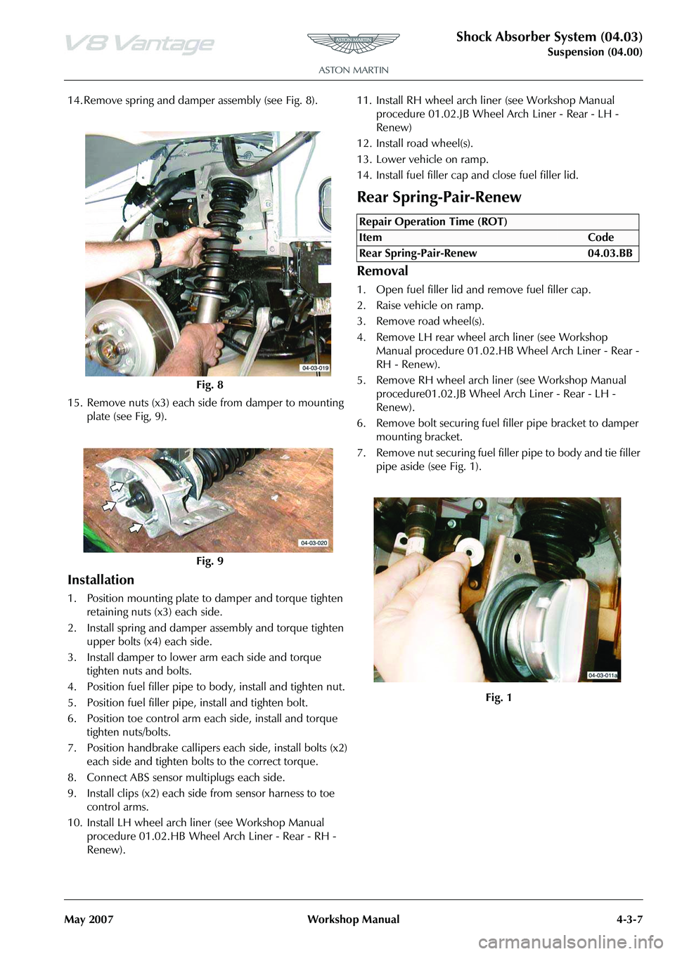
14. Remove spring and damper assembly (see Fig. 8).
15. Remove nuts (x3) each side from damper to mounting plate (see Fig, 9).
Installation
1. Position mounting plate to damper and torque tighten retaining nuts (x3) each side.
2. Install spring and damper assembly and torque tighten upper bolts (x4) each side.
3. Install damper to lower arm each side and torque tighten nuts and bolts.
4. Position fuel filler pipe to body, install and tighten nut.
5. Position fuel filler pipe, install and tighten bolt.
6. Position toe control arm each side, install and torque tighten nuts/bolts.
7. Position handbrake callipers each side, install bolts (x2) each side and tighten bolts to the correct torque.
8. Connect ABS sensor multiplugs each side.
9. Install clips (x2) each side from sensor harness to toe control arms.
10. Install LH wheel arch liner (see Workshop Manual procedure 01.02.HB Wheel Arch Liner - Rear - RH -
Renew). 11. Install RH wheel arch li
ner (see Workshop Manual
procedure 01.02.JB Wheel Arch Liner - Rear - LH -
Renew)
12. Install road wheel(s).
13. Lower vehicle on ramp.
14. Install fuel filler cap and close fuel filler lid.
Rear Spring-Pair-Renew
Removal
1. Open fuel filler lid and remove fuel filler cap.
2. Raise vehicle on ramp.
3. Remove road wheel(s).
4. Remove LH rear wheel arch liner (see Workshop Manual procedure 01.02.HB Wheel Arch Liner - Rear -
RH - Renew).
5. Remove RH wheel arch liner (see Workshop Manual procedure01.02.JB Wheel Arch Liner - Rear - LH -
Renew).
6. Remove bolt securing fuel filler pipe bracket to damper
mounting bracket.
7. Remove nut securing fuel fille r pipe to body and tie filler
pipe aside (see Fig. 1).
Fig. 8
Fig. 9
Repair Operation Time (ROT)
Page 449 of 947
Shock Absorber System (04.03)
Suspension (04.00)
May 2007 Workshop Manual 4-3-9
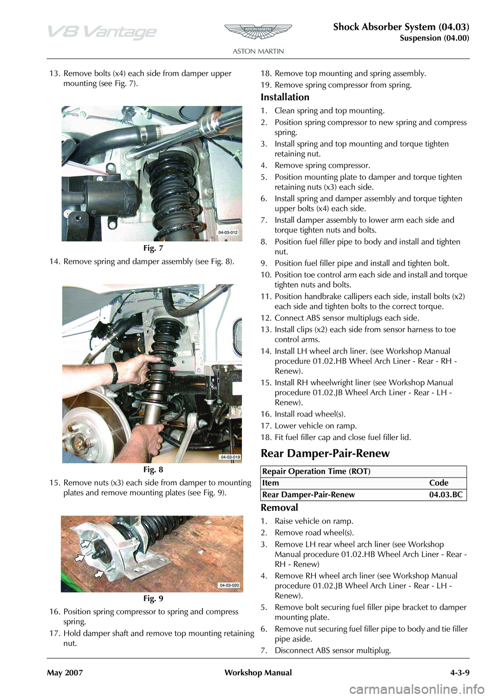
13. Remove bolts (x4) each side from damper upper mounting (see Fig. 7).
14. Remove spring and damper assembly (see Fig. 8).
15. Remove nuts (x3) each side from damper to mounting plates and remove mounting plates (see Fig. 9).
16. Position spring compresso r to spring and compress
spring.
17. Hold damper shaft and remove top mounting retaining nut. 18. Remove top mounting and spring assembly.
19. Remove spring compressor from spring.
Installation
1. Clean spring and top mounting .
2. Position spring compressor to new spring and compress
spring.
3. Install spring and top mounting and torque tighten retaining nut.
4. Remove spring compressor.
5. Position mounting plate to damper and torque tighten
retaining nuts (x3) each side.
6. Install spring and damper assembly and torque tighten upper bolts (x4) each side.
7. Install damper assembly to lower arm each side and torque tighten nuts and bolts.
8. Position fuel filler pipe to body and install and tighten nut.
9. Position fuel filler pipe and install and tighten bolt.
10. Position toe control arm each side and install and torque tighten nuts and bolts.
11. Position handbrake callipers each side, install bolts (x2) each side and tighten bolts to the correct torque.
12. Connect ABS sensor multiplugs each side.
13. Install clips (x2) each side from sensor harness to toe control arms.
14. Install LH wheel arch li ner. (see Workshop Manual
procedure 01.02.HB Wheel Arch Liner - Rear - RH -
Renew).
15. Install RH wheelwright li ner (see Workshop Manual
procedure 01.02.JB Wheel Arch Liner - Rear - LH -
Renew).
16. Install road wheel(s).
17. Lower vehicle on ramp.
18. Fit fuel filler cap and close fuel filler lid.
Rear Damper-Pair-Renew
Removal
1. Raise vehicle on ramp.
2. Remove road wheel(s).
3. Remove LH rear wheel arch liner (see Workshop Manual procedure 01.02.HB Wheel Arch Liner - Rear -
RH - Renew)
4. Remove RH wheel arch liner (see Workshop Manual procedure 01.02.JB Wheel Arch Liner - Rear - LH -
Renew).
5. Remove bolt securing fuel filler pipe bracket to damper
mounting plate.
6. Remove nut securing fuel fille r pipe to body and tie filler
pipe aside.
7. Disconnect ABS sensor multiplug.
Fig. 7
Fig. 8
Fig. 9
Repair Operation Time (ROT)