ignition ASTON MARTIN V8 VANTAGE 2010 Repair Manual
[x] Cancel search | Manufacturer: ASTON MARTIN, Model Year: 2010, Model line: V8 VANTAGE, Model: ASTON MARTIN V8 VANTAGE 2010Pages: 947, PDF Size: 43.21 MB
Page 733 of 947

Active Anti-Theft System (19.01)
Electronic Features (19.00)19-1-2 Workshop ManualIssue 5, January 2010
Electronic Features (19.00)
Active Anti-Theft System (19.01)
Alarm System Overview
All alarm and central locking operations are controll
ed from within the Central Electronic Module (CEM).
Component Descriptions
Battery Backed Sounder
This device produces the audible out-put from the alarm
system. The sounder can also house a tilt sensor to detect
unauthorised vehicle movement.
Guard Reduction Switch
Used to disable the mass movement sensor, double locking
and tilt sensor, so that people or animals can be left in the
vehicle.
Mass Movement Sensor (optional)
Detects movement within the cabin of the car using
microwaves. It is specifically designed to protect the ignition
barrel and lock.
Central Electronics Module (CEM)
This module controls the vehicle alarm system. The CEM
controls all alarm system inputs and outputs.
Driver Informatio n Module (DIM)
Instrument Cluster
The message centre right provides text messages displaying
alarm information to the user.
Ajar switches (perimeter sensors)
The car is equipped with ajar switches to sense unauthorised
access to the following areas:
Page 734 of 947

Active Anti-Theft System (19.01)
Electronic Features (19.00)
Issue 5, Jan
ua
ry 2010 Workshop Manual 19-1-3
Functional Description
Overview – Alarm
The Vehicle Alarm System (VAS) will generate an audible
and visual warning if the vehicle doors, bonnet or boot are
opened without first disarming the system using an
authorised remote transmitter key.
There are two types of alarm system:
•Standard
• High Specification (optional). Includes an interior
movement sensor and tilt sensor
The interior movement sensor offers further protection of
the ignition barrel and steering wheel lock, the tilt sensor will
detect unauthorised angular movement of the vehicle.
A Battery Backup sounder (BBS) is used to protect the
sounder from disconnection. The BBS will sound if any
attempt is made to disconnect it from the rest of the alarm
system when the vehicle is armed.
General setting
The system will be armed on the first press of the remote
transmitter ‘Lock’ button. Th e alarm system will arm and
deadlock 25 seconds after receiving the arm request.
Door open
If the alarm system is set when any door, bonnet or boot are
left open, then the alarm will be armed on all closed doors
only, 25 seconds after the alarm set command has been
requested. The open door, bonnet or boot will not be
armed. 5 seconds after the open door, bonnet or boot have
been closed, the alarm will Arm on that door, bonnet or
boot.
Disable the Alarm
The alarm will be disabled following the unlock or boot open
commands from the remote transmitter key or by turning the
ignition key in the ignition barrel.
Reduced guard mode
When the vehicle is in reduced guard mode the mass
movement and tilt sensors are disabled. This allows people
or animals to be left in the vehicle.
With doors, boot and bonnet cl osed, ignition key in position
‘0’ or ‘I’ or within 60 sec after removing the keys the reduced
guard button can be activated.
When the alarm is set, the vehicle will enter reduced guard
mode. To deactivate reduced guard mode simply insert and
turn the ignition key to position ‘II’.
If the alarm is deactivated and then activated without turning
the ignition key to position ‘II’ first, then the reduced guard
mode will remain active.
Alarm Cycle
When the alarm has been activated there will be two
outputs, these are listed below:
Audible output device (Siren)
The audible alarm signal is generated by the battery backed
sounder. Duration of one alarm cycle is 25 seconds. The
maximum number of cycles is ten.
Visible output device DI’s
The turn indicators are activated during and alarm cycle. The
alarm signal is given by flashing all direction indicators for 5
minutes. Following an alarm cycle the vehicle alarm will
remain set.
Panic Alarm
The Panic Alarm is to be used in emergency situations for
attracting attention while in or outside the vehicle.
Activate Panic Alarm
The Panic Alarm can be activated using the Panic Alarm
button on the remote transmitter, there are two ways to
initiate the feature:
• Press the Panic Alarm button for a minimum time of 3 seconds.
• Press the Panic Alarm button tw ice, the second press must
be made within 3 seconds from the first press.
Deactivate Panic Alarm
The panic alarm cannot be deactivated for the first 5 seconds
of operation following its activation. Following the first 5
seconds of the panic alarm cycle, it can then be deactivated
in following ways:
• Pressing the panic button on the remote transmitter.
• The activation time has exceeded (25 seconds).
Panic alarm cycle
When active, the DI’s will flash and the vehicle horn will
sound for 25 seconds.
The ignition key must have be en in position ‘II’ first.
Page 735 of 947
Active Anti-Theft System (19.01)
Electronic Features (19.00)19-1-4 Workshop ManualIssue 5, January 2010
Remote Transmitter
The security system allows up to eight remote transmitters to
be used for controlling the system functions.
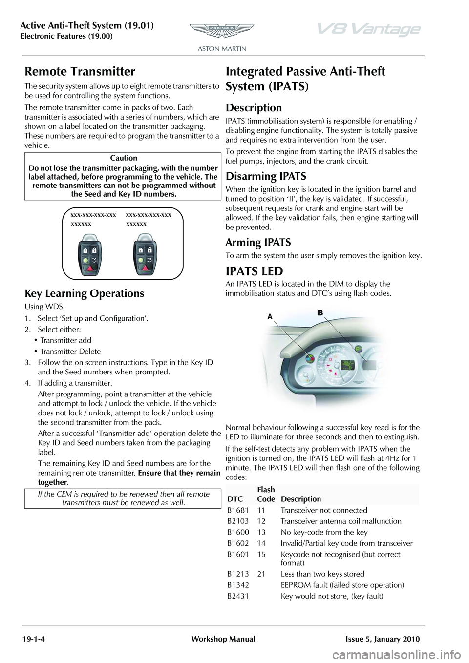
The remote transmitter come in packs of two. Each
transmitter is associated with a
series of numbers, which are
shown on a label located on the transmitter packaging.
These numbers are required to program the transmitter to a
vehicle.
Key Learning Operations
Using WDS.
1. Select ‘Set up and Configuration’.
2. Select either:
• Transmitter add
• Transmitter Delete
3. Follow the on screen instructions. Type in the Key ID and the Seed numbers when prompted.
4. If adding a transmitter. After programming , point a transmitter at the vehicle
and attempt to lock / unlock the vehicle. If the vehicle
does not lock / unlock, attempt to lock / unlock using
the second transmitter from the pack.
After a successful ‘Transmitter add’ operation delete the
Key ID and Seed numbers taken from the packaging
label.
The remaining Key ID and Seed numbers are for the
remaining remote transmitter. Ensure that they remain
together .
Integrated Passive Anti-Theft
System (IPATS)
Description
IPATS (immobilisation system) is responsible for enabling /
disabling engine functionality. The system is totally passive
and requires no extra inte rvention from the user.
To prevent the engine from starting the IPATS disables the
fuel pumps, injectors, and the crank circuit.
Disarming IPATS
When the ignition key is located in the ignition barrel and
turned to position ‘II’, the key is validated. If successful,
subsequent requests for crank and engine start will be
allowed. If the key validation fa ils, then engine starting will
be prevented.
Arming IPATS
To arm the system the user simply removes the ignition key.
IPATS LED
An IPATS LED is located in the DIM to display the
immobilisation status and DTC’s using flash codes.
Normal behaviour following a su ccessful key read is for the
LED to illuminate for three seconds and then to extinguish.
If the self-test detects any problem with IPATS when the
ignition is turned on, the IPAT S LED will flash at 4Hz for 1
minute. The IPATS LED will then flash one of the following
codes:
Caution
Do not lose the transmitter packaging, with the number
label attached, before progra mming to the vehicle. The
remote transmitters can not be programmed without the Seed and Key ID numbers.
If the CEM is required to be renewed then all remote
transmitters must be renewed as well.
XXX-XXX-XXX-XXX
XXXXXX XXX-XXX-XXX-XXX
XXXXXX
DTC
Flash
Code
Description
B1681 11 Transceiver not connected
B2103 12 Transceiver antenna coil malfunction
B1600 13 No key-code from the key
B1602 14 Invalid/Partial key code from transceiver
B1601 15 Keycode not recognised (but correct format)
B1213 21 Less than two keys stored
B1342 EEPROM fault (failed store operation)
B2431 Key would not store, (key fault)
Page 736 of 947
Active Anti-Theft System (19.01)
Electronic Features (19.00)
Issue 5, Jan
ua
ry 2010 Workshop Manual 19-1-5
Key Programming
All vehicle keys are required to perform key programming.
Using AMDS.
1. Insert the first key to the ignition.
2. Select ‘Set up and Configuration’ on AMDS.
3. Select either: •Key Learn
•Key Delete
4. Follow the on screen instructions. You will be prompted to program successiv e keys as required.
Count Keys
Using AMDS.
Select Count keys to check how many keys are programmed
into the vehicle security.
Maintenance
Tracker-Renew
Removal
1. Remove IP assembly (see Workshop Manual procedure
01.12.AB Instrument Panel - Facia Assembly - Remove
for Access and Refit).
2. Disconnect multiplugs (x2) from tracker horizon and
GPS antenna assembly.
3. Remove nuts (x2) securing tracker assembly to mounting bracket.
4. Release GPS antenna from bracket, remove tracker assembly.
5. Remove screws (x2) securing tracker horizon to bracket.
Intallation
1. Position tracker horizon to bracket, install and tighten screws (x2).
2. Install tracker horizon assenb ly, install and tighten nuts
(x2).
3. Install tracker GPS antenna in bracket.
4. Connect multiplugs (x2).
5. Install IP assembly (see Workshop Manual procedure 01.12.AB Instrument Panel - Facia Assembly - Remove
for Access and Refit).
Mass Movement Sensor-Renew
Removal
1. Remove front header console assembly (see Workshop Manual procedure 01.05.BC Console Assembly - Front
Header - Renew)
2. Remove RH front pillar upper trim panel (see Workshop Manual procedure 01.05.BD Trim - Upper Panel - Front
Pillar - RH - Renew).
3. Remove LH front pillar uppe r trim panel (see Workshop
Manual procedure 01.05.BE Trim - Upper Panel - Front
Pillar - LH - Renew).
4. Remove sun visors Allen screws (x4).
5. Remove sunvisors.
6. Remove screws (x2) front header to body.
7. Remove front header panel.
8. Remove mass movement sensor from front header.
Installation
1. Install mass movement sensor.
2. Install front header panel.
3. Position sun visors and install screws (x4).
4. Install RH front pillar uppe r trim panel (see Workshop
Manual procedure 01.05.BD Trim - Upper Panel - Front
Pillar - RH - Renew).
5. Install LH front pillar upper trim panel (see Workshop Manual procedure 01.05.BE Trim - Upper Panel - Front
Pillar - LH - Renew).
6. Install front header console assembly (see Workshop Manual procedure 01.05.BC Console Assembly - Front
Header - Renew).
Pats Tranceiver ECU (Pre-08 MY Only) -
Remove and Install
Removal
1. Remove the top and bottom shrouds for the steering column (Refer to ’Top and Bottom Shrouds for the
Steering Column - Remove and Install’, page 11-4-4).
2. Release the clips that attach the wiper switch to its mounting.
3. Release the wiper switch from its mounting.
4. Move the wiper switch away to give access.
5. Remove the self-tapping screw that attaches the PATS tranceiver ECU (ECU) to the steering column.
6. Disconnect the electrical connector for the ECU.
7. Remove the ECU.
Installation
1. Put the ECU in position on the steering column.
2. Install the self-tapping screw to attach the ECU.
3. Connect the electrical connector for the ECU.
4. Install the wiper switch in the mounting.
Note: You will need a
ccess to the Internet
Repair Operation Time (ROT)
Repair Operation Time (ROT)
Repair Operation Time (ROT)
Page 795 of 947

Squeaks and Rattles Repair Manual
July 2010 Page 11 of 21
Figure 6
10. Connect the electrical connector to ignition start/stop switch (refer to Figure 7).
Figure 7
11. Connect the electrical connectors to each of the four transmission control switches (refer to Figure 8).
Figure 8
12. Make sure that the heater vents are correctly aligned.
Page 799 of 947

Squeaks and Rattles Repair Manual
July 2010 Page 15 of 21
Figure 6
9. Install the sat-nav top panel.
10. Put the instrument panel into po sition (refer to Figure 7).
Figure 7
11. Connect the electrical connector to ignition start/stop switch (refer to Figure 8).
Figure 8
12. Connect the electrical connectors to each of the four transmission control switches (refer to Figure 9).
Page 803 of 947
Squeaks and Rattles Repair Manual
July 2010 Page 19 of 21
Figure 6
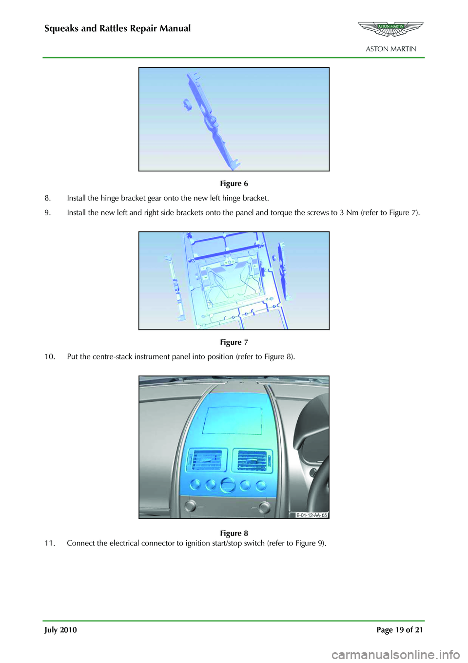
8. Install the hinge bracket gear onto the new left hinge bracket.
9. Install the new left and right side brackets onto the pane l and torque the screws to 3 Nm (refer to Figure 7).
Figure 7
10. Put the centre-stack instrument panel into position (refer to Figure 8).
Figure 8
11. Connect the electrical connector to ignition start/stop switch (refer to Figure 9).
Page 830 of 947
Electronics Training Programme
Answering Incoming Calls
When receiving an incoming call, the system responds with ‘Call from < Caller ID>’, if available. If
Caller ID is not available:
• The system plays the ‘in-band’ ring tone, if the phone supports it.
• If no ‘in-band’ ring tone is supported , the system generates a local ring tone.
There are two methods of answering an incoming call:
1. Press the button.
2. Press the ‘answer call’ key on the phone’s handset.
Ending Calls
Use one of the following three methods to end a call:
1. Press the button. When prompted say ‘Hang Up’. The responds with ‘Call ended’.
2. Press the button.
3. Pres the ‘end call’ key on the phone’s handset.
Transfer A Call
If you wish t transfer a call from the car to your phone either:
• Press the button. When prompted say ‘privacy mode’.
Or
• Press and hold the button.
• Turn the vehicle ignition to 0 (off) (If your p hone asks to switch to handset mode press yes.).
To transfer a call from your phone to the car either:
• Press the button. When prompted say ‘handsfree mode’.
Or
• Press the button.
• Turn the car ignition to position II (on).
Note: Some mobile phones will end the Bluetooth co nnection. If this happens the only way of
transferring to the vehicle is by the mobile phone menu (if supported).
Rejecting A Call
To reject an incoming call either:
• Press the button. The system will respond ‘call rejected’.
Or
• Press the ignore, end or hang-up key on the phone handset.. The system responds with ‘call
ended’.
25
Page 834 of 947

Electronics Training Programme
The procedure to change the selected language is:
Warning: When changing the system’s language, all contac ts in the Bluetooth contacts list are deleted.
1. Press and hold the button while turning on the vehicle ignition. Continue holding the
button for at least 10 seconds.
The system enters language selection mode and re sponds with ‘Language Menu. Press volume up or
down to change language’.
2. Use the volume Up / Down button to scroll through the language choices. As a language appears, the system plays the prompt for that la nguage (For example: ‘English. To choose this
language, restart the vehicle’.).
When the desired language has been selected, turn t he vehicle ignition to 0 (off). Wait for 6 seconds,
then switch the ignition to II (on), the new language is then loaded.
29
Page 836 of 947
Electronics Training Programme
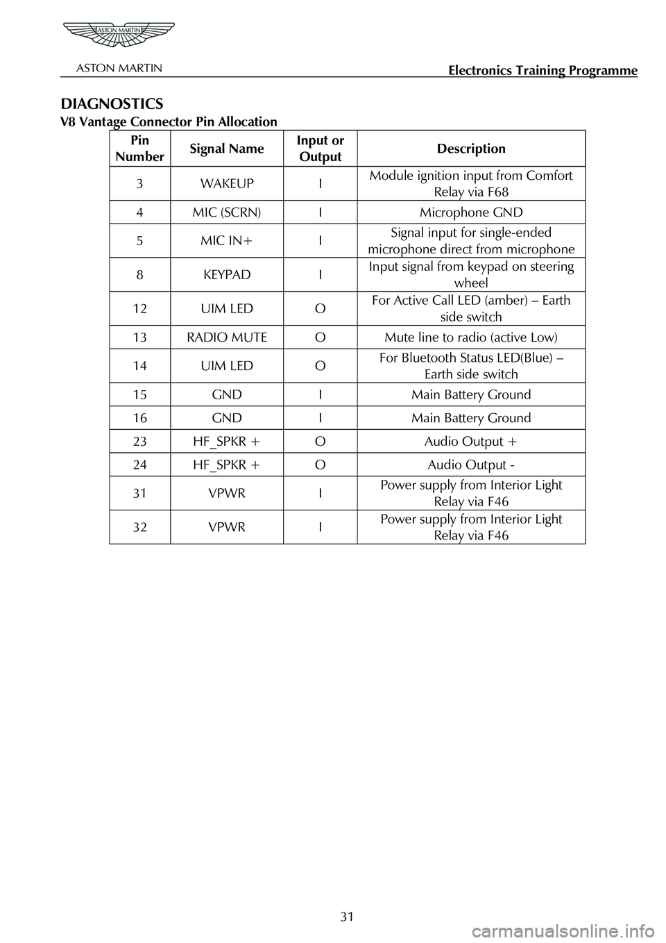
DIAGNOSTICS
V8 Vantage Connector Pin Allocation
Pin
Number Signal Name Input or
Output Description
3 WAKEUP I Module ignition input from Comfort
Relay via F68
4 MIC (SCRN) I Microphone GND
5 MIC IN+ I Signal input for single-ended
microphone direct from microphone
8 KEYPAD I Input signal from keypad on steering wheel
12 UIM LED O For Active Call LED (amber) – Earth
side switch
13 RADIO MUTE O Mute line to radio (active Low)
14 UIM LED O For Bluetooth Status LED(Blue) – Earth side switch
15 GND I Main Battery Ground
16 GND I Main Battery Ground
23 HF_SPKR + O Audio Output +
24 HF_SPKR + O Audio Output -
31 VPWR I Power supply from Interior Light Relay via F46
32 VPWR I Power supply from Interior Light Relay via F46
31