steering wheel ASTON MARTIN V8 VANTAGE 2010 Repair Manual
[x] Cancel search | Manufacturer: ASTON MARTIN, Model Year: 2010, Model line: V8 VANTAGE, Model: ASTON MARTIN V8 VANTAGE 2010Pages: 947, PDF Size: 43.21 MB
Page 792 of 947

Squeaks and Rattles Repair Manual
Page 8 of 21 Issue 3
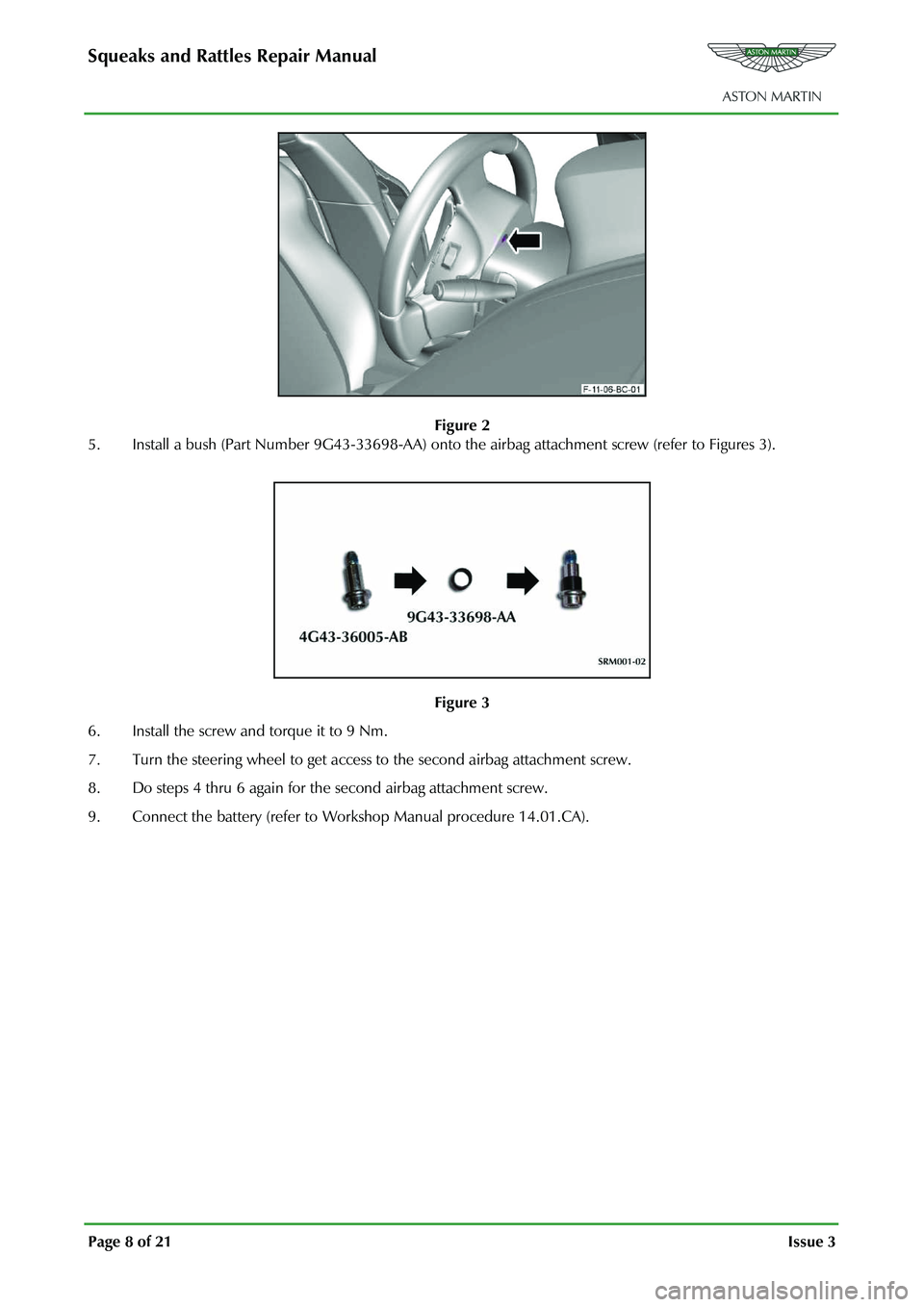
Figure 2
5. Install a bush (Part Number 9G43-33698-AA) onto th e airbag attachment screw (refer to Figures 3).
Figure 3
6. Install the screw and torque it to 9 Nm.
7. Turn the steering wheel to get access to the second airbag attachment screw.
8. Do steps 4 thru 6 again for the second airbag attachment screw.
9. Connect the battery (refer to Work shop Manual procedure 14.01.CA).
Page 814 of 947

Electronics Training Programme
Description
The Bluetooth Module controls the Bluetooth system on all cars. This module is a stand-alone unit,
which is not connected to any communication network on the car. The module is located on the
drivers side of the Instrument Pack (IP) ju st above the pedals (see page opposite).
The components of the system are:
1. Microphone
2. Bluetooth switches (steering wheel)
3. LED Indicator
4. Bluetooth Module
5. Amplifier (audio)
6. Switcher box (V8 Vantage only)
If a DB9 is installed with both the ‘in-car’ ph one and the Bluetooth systems and both systems are
active then the Bluetooth system will override the ‘i n-car’ phone system. An active call on the ‘in-car’
phone will be ended if a call is re ceived on the Bluetooth system or any of the Bluetooth menus are
used.
The Bluetooth module has been designed to meet the following parameters:
Parameter Units Nominal Lower Limit Upper Limit
Battery Voltage Volts N/A 10.5 16.0
Nominal Voltage Volts 13.2 12.2 14.2
Over Voltage (for 1 minute) Volts 24.0 18.0 25.0
Operating Current mA 225-300 <300uA (sleep) <1.5A
Room Temperature °C 25 15 35
Operating Temperature °C N/A -30 70
Storage Temperature °C N/A -40 85
9
Page 820 of 947

Electronics Training Programme
INPUTS
The Bluetooth system relies on a number of signals it receives either from the car (via hard wiring) or
the users phone (via wireless Bluetooth communication network).
The Bluetooth system will only function if the us ers mobile phone has Bluetooth enabled and it is
‘paired’ to the car. For more information refer to the user’s guide for your mobile phone.
V8 Vantage Power Supplies
Description Supplied From Source Protection
Wakeup signal Central Electronic Module Comfort Relay F68 (5 Amp)
Power supply 1 Central Electronic Module Interior Lights Relay F46 (5Amp)
Power supply 2 Central Electronic Module Interior Lights Relay F46 (5Amp)
DB9 Power Supplies
Description Supplied From Source Protection
Wakeup signal Central Electronic Module Comfort Relay F69 (5 Amp)
Power supply 1 Central Electronic Module Interior Lights Relay F46 (5Amp)
Power supply 2 Central Electronic Module Interior Lights Relay F46 (5Amp)
V8 Vantage Signal Inputs
Input Description Signal Characteristic
MIC In Input signal from microphone Varying current signal direct from microphone
Keypad Steering wheel controls input Variable resistance to earth signal
DB9 Signal Inputs
Input Description Signal Characteristic
MIC In + Input signal from microphone Varying current signal supplied via amplifier
MIC In - Input signal from microphone Varying current signal supplied via amplifier
Keypad Steering wheel controls inpu t Variable resistance to earth
Screens
Some of the signals in and out of the Bluetooth modu le require screening to avoid interference being
picked up. A signal screen is a single wire running along side t he signal wire(s) which will absorb
electro magnetic interference (EMI).
The Bluetooth module on the V8 Vantage features only one screen so as to protect the signal from the
microphone. This screen wire is simply an earth but it is also used as a datum from which to reference
the microphone signal.
The Bluetooth module used on DB9’s features two screens. One is as on the V8 Vantage but is used
only as a screen (because the microphone signal from the amplifie r has two signal wires) and no
datum is required. The second screen on the module is used to screen the ‘Lineout’ signals to the
amplifier. As with the microphone scr een this wire is connected to earth.
15
Page 836 of 947

Electronics Training Programme
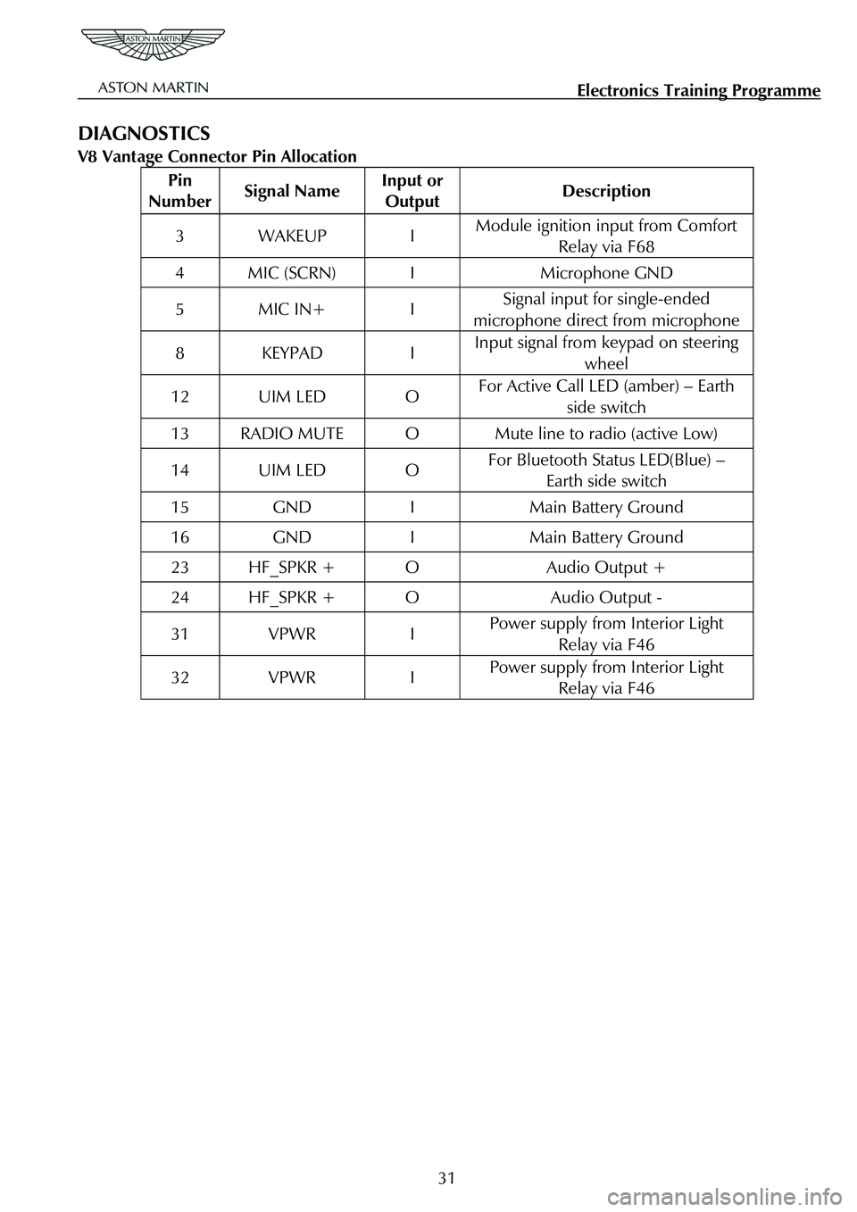
DIAGNOSTICS
V8 Vantage Connector Pin Allocation
Pin
Number Signal Name Input or
Output Description
3 WAKEUP I Module ignition input from Comfort
Relay via F68
4 MIC (SCRN) I Microphone GND
5 MIC IN+ I Signal input for single-ended
microphone direct from microphone
8 KEYPAD I Input signal from keypad on steering wheel
12 UIM LED O For Active Call LED (amber) – Earth
side switch
13 RADIO MUTE O Mute line to radio (active Low)
14 UIM LED O For Bluetooth Status LED(Blue) – Earth side switch
15 GND I Main Battery Ground
16 GND I Main Battery Ground
23 HF_SPKR + O Audio Output +
24 HF_SPKR + O Audio Output -
31 VPWR I Power supply from Interior Light Relay via F46
32 VPWR I Power supply from Interior Light Relay via F46
31
Page 837 of 947

Electronics Training Programme
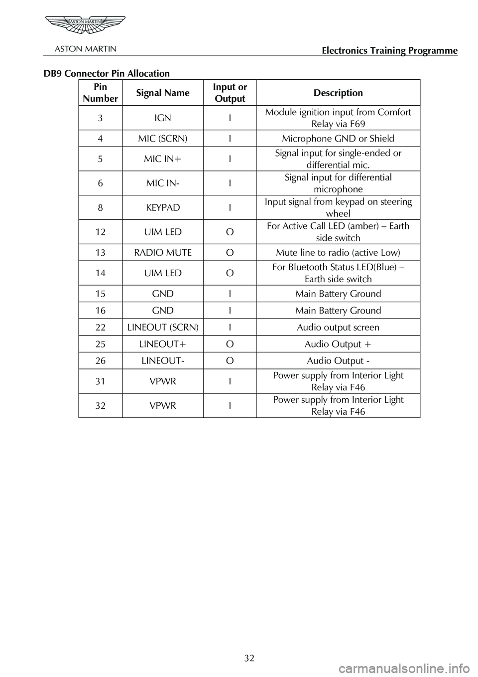
DB9 Connector Pin Allocation
Pin
Number Signal Name Input or
Output Description
3 IGN I Module ignition input from Comfort
Relay via F69
4 MIC (SCRN) I Microphone GND or Shield
5 MIC IN+ I Signal input for single-ended or
differential mic.
6 MIC IN- I Signal input for differential microphone
8 KEYPAD I Input signal from keypad on steering
wheel
12 UIM LED O For Active Call LED (amber) – Earth side switch
13 RADIO MUTE O Mute line to radio (active Low)
14 UIM LED O For Bluetooth Status LED(Blue) – Earth side switch
15 GND I Main Battery Ground
16 GND I Main Battery Ground
22 LINEOUT (SCRN) I Audio output screen
25 LINEOUT+ O Audio Output +
26 LINEOUT- O Audio Output -
31 VPWR I Power supply from Interior Light Relay via F46
32 VPWR I Power supply from Interior Light Relay via F46
32