steering wheel ASTON MARTIN V8 VANTAGE 2010 Service Manual
[x] Cancel search | Manufacturer: ASTON MARTIN, Model Year: 2010, Model line: V8 VANTAGE, Model: ASTON MARTIN V8 VANTAGE 2010Pages: 947, PDF Size: 43.21 MB
Page 624 of 947

Steering Column Switches (11.05)
Steering (11.00)
Issue 4, November 2008 Workshop Manual 11-5-3
8. Move the airbag module to get access to the two electrical connectors (Refer to FIgure 2).
Figure 2
9. Disconnect the two electrical connector for the airbag module.
10. Remove the airbag module and keep it in an approved storage area.
11. Turn the steering to the centre position.
12. Disconnect the electrical connector for the steering
wheel harness (Refer to FIgure 3).
Figure 3
13. Remove the M10 Torx screw that attaches the steering wheel (Refer to FIgure 4).
Figure 4
14. Remove the steering wheel assembly. 15. Apply tape to hold the rotary coupler in its central
position (Refer to FIgure 5).
Figure 5
16. Remove the top and bottom steering column shrouds (Refer to ’Top and Bottom Shrouds for the Steering
Column - Remove and Install’, page 11-4-4).
17. Remove the screw that attaches the load-spread plate to the steering column (Refer to FIgure 6).
Figure 6
18. Remove the load-spread plate.
19. Release the clips that attach the column switches to the rotary coupler.
20. Remove the column switches from the rotary coupler.
Page 625 of 947

Steering Column Switches (11.05)
Steering (11.00)
11-5-4 Workshop Manual Issue 4, November 2008
21. Remove the electrical conne ctor (1) from the rotary
coupler (Refer to FIgure 7).
Figure 7
22. Release the two clips that attach the rotary coupler to the steering column and remove the rotary coupler.
Install
1. Put tape on the rotary coupler to hold it in its central position.
2. Push the rotary coupler onto the steering column until the two clips engage.
3. Install the electrical connector (1) for the rotary coupler.
4. Install the column switches into the rotary coupler.
5. Connect the electrical connectors for the column switches.
6. Put the load-spread plate in position on the steering column.
7. Install the screw that attaches the load-spread plate.
8. If a rotary coupler is to be installed that is not new, remove the tape used to hold it in its central position.
9. For a new rotary coupler, remove the locking key.
10. Install the top and bottom steering column shrouds (Refer to ’Top and Bottom Shrouds for the Steering
Column - Remove and Install’, page 11-4-4).
11. Put the electrical cables from the rotary coupler through the steering wheel.
12. Align and install the steering wheel assembly.
13. Install and torque the M10 screw that attaches the steering wheel (Refer to ’Specifications’, page 11-6-1).
14. Connect the electrical connector for the steering wheel harness.
15. Connect the two electrical cables to the airbag module.
16. Put the airbag module in position. 17. Turn the steering wheel to get access to install one of the
two airbag module M6 attachment screws.
18. Install the first M6 attachment screw.
19. Turn the steering wheel to get access to install the second airbag module M6 attachment screw.
20. Install the second M6 attachment screw.
21. Connect the vehicle battery.
Wiper Switch for the Steering Column -
Remove and Install
Remove
1. Remove the top shroud from the steering column (Refer to ’Top Shroud for the Steering Column - Remove and
Install’, page 11-4-1).
2. Release the clips that attach the wiper switch to its mounting.
3. Release the wiper switch from its mounting.
4. Disconnect the electrical connector for the wiper switch.
5. Remove the wiper switch.
Install
1. Connect the electrical connector to the wiper switch.
2. Install the wiper switch in the mounting.
3. Make sure that the clips that attach the switch are correctly engaged.
4. Install the top shroud to the steering column (Refer to ’Top Shroud for the Steering Column - Remove and
Install’, page 11-4-1).
Caution
Align the steering wheel and the rack to the centre position during assembly. If you do not, the rotary
coupling can be damaged. Al so, it can be difficult to
align the steering wheel in the straight-ahead position.
Repair Operation Time (ROT)
ItemCode
Wiper Switch for th e Steering Column -
Remove and Install 11.06.EL
Page 626 of 947

Steering Wheel (11.06)
Steering (11.00)
May 2007 Workshop Manual 11-6-1
Steering (11.00)
Steering Wheel (11.06)
Specifications
Maintenance
Steering Wheel-Renew
Remove
1. Remove the driver's airbag module (Refer to ’Driver’s Airbag Module - Remove an d Install’, page 11-6-1).
2. Turn the steering to the centre position.
3. Disconnect the vehicle battery.
4. Disconnect the electrical connector for the steering wheel harness.
Figure A11-06-1096
5. Remove the M10 Torx screw that attaches the steering wheel.
Figure A11-06-1095
6. Remove the steering wheel assembly.
7. Apply tape to hold the rotary coupler in its central position.
Installation
1. Put the electrical cables from the rotary coupler through
the steering wheel.
2. Align and install the steering wheel assembly.
3. Install and torque the M10 screw that attaches the steering wheel (Refer to ’S pecifications’, page 11-6-1).
4. Connect the electrical connector for the steering wheel harness.
5. Install the driver's airbag module (Refer to ’Driver’s Airbag Module - Remove and Install’, page 11-6-1).
6. Connect vehicle battery.
Driver’s Airbag Module - Remove and
Install
Remove
For Pre-08MY vehicles:
1. Put the key in the ignition switch and turn it to position 1 to release the Electronic Steering Column
Lock (ESCL).
Torque Figures
DescriptionNm.lb/ft
Steering Wheel Attachment Screw 40 29.5
Airbag Module Att achment Screws 9 6.6
Repair Operation Time (ROT)
Caution
Align the steering wheel and the rack to the centre position during assembly. If you do not, the rotary
coupling can be damaged. Also, it can be difficult to
align the steering wheel in the straight-ahead position.
Repair Operation Time (ROT)
Page 627 of 947

Steering Wheel (11.06)
Steering (11.00)11-6-2 Workshop Manual May 2007
For 08MY vehicles or newer:
2. Put the Emotion Control Unit (ECU) into the docking station at position 2 to release the ESCL..
3. Disconnect the vehicle battery.
4. Turn the steering wheel to get access to one of the two M6 screws that attach the airbag module.
Figure A11-06-1093
5. Remove the M6 screw.
6. Turn the steering wheel to get access to the second M6 screw that attaches the airbag module.
7. Remove the second M6 screw.
8. Move the airbag module to get access to the two electrical connectors.
Figure A11-06-1094
9. Disconnect the two electrical connector for the airbag module.
10. Remove the airbag module and keep it in an approved storage area.
Install
1. Connect the two electrical cables to the airbag module.
2. Put the airbag module in position.
3. Turn the steering wheel to get access to install one of the two airbag module M6 attachment screws. 4. Install and torque the first M6 attachment screw.
5. Turn the steering wheel to get access to install the
second airbag module M6 attachment screw.
6. Install and torque the second M6 attachment screw.
7. Connect the vehicle battery.
WAR NI NG
LEAVE THE VEHICLE FOR TWO MINUTES AFTER YOU
DISCONNECT THE BATTERY BEFORE YOU DO WORK.
IF YOU DO NOT, THE AIRBAG SYSTEM CAN OPERATE AND CAUSE INJURY.
Page 715 of 947

Wiring and Circuit Protection (18.01)
Electric Distribution/E lectronic Control (18.00)
18-1-26 Workshop Manual May 2007
5. Remove screws (x4), securing centre stack assembly to
IP.
6. Release centre stack assembly, disconnect multiplugs (x12).
7. Remove nuts (x3) securing blower assembly to instrument pack.
8. Disconnect multiplug and lucar connector to blower assembly.
9. Remove screws (x7), remove steering column shrouds.
10. Remove screw securing load spread plate to column. Collect column shrouds mounting bracket.
11. Release clips (x2), column switch harness to load spread plate.
12. Disconnect multiplugs (x3), steering column switches.
13. Disconnect multiplugs (x2) ignition switch assembly.
14. Remove DIP panel (see Workshop Manual procedure 13.01.AA Module - Driver Information - Renew).
15. Disconnect multiplug to RKE receiver.
16. Release facia harness to main harness multiplugs (x5) from IP bracket RH side.
17. Disconnect multiplug to glovebox latch motor.
18. Disconnect multiplug to pass engers airbag on/off switch.
19. Disconnect multiplug to solar sensor.
20. Disconnect multiplug to centre speaker.
21. Disconnect multiplugs (x2) to footwell lamps.
22. Release diagnostic sockets (x2) from bracket.
23. Disconnect multiplug to CD player.
24. Disconnect multiplug to headlamp levelling unit.
25. Disconnect multiplug to PDC sounder.
26. Disconnect multiplugs (x2) to master lighting switch.
27. Disconnect multiplug to interior guard switch.
28. Disconnect multiplug to steering rotation sensor.
29. Release facia harness to main harness multiplugs (x6) from IP bracket LH side.
30. Release harness clips from instrument panel.
31. Remove harness assembly.
Installation
1. Position harness to IP and secure in clips (x21).
2. Install facia harness to main harness multiplugs (x6) to IP bracket LH side.
3. Connect multiplug (X1) to steering rotation sensor.
4. Connect multiplug (X1) to interior guard switch.
5. Connect multiplugs (x2) to master lighting switch.
6. Connect multiplug (x1) to PDC sounder.
7. Connect multiplug (x1) to headlamp levelling unit.
8. Connect multiplug (X1) to CD player.
9. install diagnostic sockets (x2) to bracket.
10. Connect multiplugs (x2) to footwell lamps.
11. Connect multiplug (X1) to centre speaker.
12. Connect multiplug (X1) to solar sensor.
13. Connect multiplug to passengers airbag on/off switch.
14. Connect multiplug (X1) to glovebox latch motor. 15. Install facia harness to main harness multiplugs (x5) from
IP bracket RH side.
16. Connect multiplug to RKE receiver.
17. Install DIP panel (see Workshop Manual procedure 13.01.AA Module - Driver Information - Renew).
18. Connect multiplugs (x2) ignition switch assembly.
19. Connect multiplugs (x3), steering column switches.
20. Secure column switch harness in clips (x2) to load spread plate.
21. Position column shroud brackets and Install screw securing load spread plate to column.
22. Install steering column shrouds, (screws x7).
23. Connect multiplug (X1) an d lucar connector (X1) to
blower assembly.
24. Position blower assembly to IP and install nuts (x3)
25. Position centre stack assembly and connect multiplugs (x12).
26. install screws (x4), securing centre stack assembly to IP.
27. Install instrument panel bezel assembly (see Workshop Manual procedure 01.12.AV Bezel Assembly -
Instrument Panel - Renew).
28. Connect tube from 'In-car' temperature sensor and install heater assembly.
29. Connect multiplugs (x6) heater assembly.
30. Install IP assembly (see Workshop Manual procedure
01.12.AB Instrument Panel - Facia Assembly - Remove
for Access and Refit).
Cabin Harness Assembly-Renew
Removal
1. Disconnect vehicle battery.
2. Remove instrument panel (see Workshop Manual procedure 01.12.AB Instrume nt Panel - Facia Assembly
- Remove for Access and Refit).
3. Remove front header panel (see Workshop Manual procedure 01.05.BB Panel Assembly - Header - Renew).
4. Remove central electronic module (see Workshop Manual procedure 18.01.LC Module - Central
Electronic - Renew).
5. Remove RH rear wheel arch liner (see Workshop Manual procedure 01.02.JB Wheel Arch Liner - Rear -
LH - Renew).
6. Remove screw securing LH and RH quarter trim middle section to rear bulkhead cover.
Warning
Always connect the battery earth (- ve) terminal last.
Repair Operation Time (ROT)
ItemCode
Cabin Harness Assembly-Renew 18.01.GB
Warning
To prevent damage to elec trical components, always
disconnect the vehicle battery when working on the
vehicle's electrical system. The earth lead (- ve) must be
disconnected first and reconnected last.
Page 734 of 947

Active Anti-Theft System (19.01)
Electronic Features (19.00)
Issue 5, Jan
ua
ry 2010 Workshop Manual 19-1-3
Functional Description
Overview – Alarm
The Vehicle Alarm System (VAS) will generate an audible
and visual warning if the vehicle doors, bonnet or boot are
opened without first disarming the system using an
authorised remote transmitter key.
There are two types of alarm system:
•Standard
• High Specification (optional). Includes an interior
movement sensor and tilt sensor
The interior movement sensor offers further protection of
the ignition barrel and steering wheel lock, the tilt sensor will
detect unauthorised angular movement of the vehicle.
A Battery Backup sounder (BBS) is used to protect the
sounder from disconnection. The BBS will sound if any
attempt is made to disconnect it from the rest of the alarm
system when the vehicle is armed.
General setting
The system will be armed on the first press of the remote
transmitter ‘Lock’ button. Th e alarm system will arm and
deadlock 25 seconds after receiving the arm request.
Door open
If the alarm system is set when any door, bonnet or boot are
left open, then the alarm will be armed on all closed doors
only, 25 seconds after the alarm set command has been
requested. The open door, bonnet or boot will not be
armed. 5 seconds after the open door, bonnet or boot have
been closed, the alarm will Arm on that door, bonnet or
boot.
Disable the Alarm
The alarm will be disabled following the unlock or boot open
commands from the remote transmitter key or by turning the
ignition key in the ignition barrel.
Reduced guard mode
When the vehicle is in reduced guard mode the mass
movement and tilt sensors are disabled. This allows people
or animals to be left in the vehicle.
With doors, boot and bonnet cl osed, ignition key in position
‘0’ or ‘I’ or within 60 sec after removing the keys the reduced
guard button can be activated.
When the alarm is set, the vehicle will enter reduced guard
mode. To deactivate reduced guard mode simply insert and
turn the ignition key to position ‘II’.
If the alarm is deactivated and then activated without turning
the ignition key to position ‘II’ first, then the reduced guard
mode will remain active.
Alarm Cycle
When the alarm has been activated there will be two
outputs, these are listed below:
Audible output device (Siren)
The audible alarm signal is generated by the battery backed
sounder. Duration of one alarm cycle is 25 seconds. The
maximum number of cycles is ten.
Visible output device DI’s
The turn indicators are activated during and alarm cycle. The
alarm signal is given by flashing all direction indicators for 5
minutes. Following an alarm cycle the vehicle alarm will
remain set.
Panic Alarm
The Panic Alarm is to be used in emergency situations for
attracting attention while in or outside the vehicle.
Activate Panic Alarm
The Panic Alarm can be activated using the Panic Alarm
button on the remote transmitter, there are two ways to
initiate the feature:
• Press the Panic Alarm button for a minimum time of 3 seconds.
• Press the Panic Alarm button tw ice, the second press must
be made within 3 seconds from the first press.
Deactivate Panic Alarm
The panic alarm cannot be deactivated for the first 5 seconds
of operation following its activation. Following the first 5
seconds of the panic alarm cycle, it can then be deactivated
in following ways:
• Pressing the panic button on the remote transmitter.
• The activation time has exceeded (25 seconds).
Panic alarm cycle
When active, the DI’s will flash and the vehicle horn will
sound for 25 seconds.
The ignition key must have be en in position ‘II’ first.
Page 737 of 947

Active Anti-Theft System (19.01)
Electronic Features (19.00)19-1-6 Workshop ManualIssue 5, January 2010
5. Make sure that the clips that attach the switch are
correctly engaged.
6. Install the top and bottom steering column shrouds (Refer to ’Top and Bottom Shrouds for the Steering
Column - Remove and Install’, page 11-4-4).
Hood Latch Switch-Renew
Removal
1. Remove grille (see Workshop Manual procedure 01.08.AA Grille - Radiator - Renew).
2. Remove slam panel (bolts x12).
3. Remove bolts (x4) securing PAS oil cooler.
4. Remove bolts securing crossmember to inner wing (x4).
5. Remove bolts and spacers securing crossmember to wing (x2).
6. Move crossmember to one side and lift up clear of location (protect paintwork).
7 . D i s c o n n e c t b o n n e t l a t c h m u l t i p l u g .
8. Remove switch from latch body.
Installation
1. Install switch to latch body.
2. Connect bonnet latch multiplug.
3. Install crossmember (as removed).
4. Install bolts and spacers securing crossmember to wing (x2).
5. Install bolts securing crossmember to inner wing (x4).
6. Install bolts (x4) securing PAS oil cooler.
7. Install slam panel (bolts x12).
8. Install grille (see Workshop Manual procedure 01.08.AA
Grille - Radiator - Renew).
Alarm Siren Assembly - Remove and
Install
Removal
1. Remove the left rear wheel (refer to Workshop Manual procedure 04.04.EC).
2. Remove the four self-tapping screws and the scrivet that attach the rear of the left, rear wheelarch liner.
3. Move the wheelarch liner away to get access to the alarm siren assembly (siren).
4. Remove the the drain hose for the fuel filler from the clips.
5. Move the drain hose for the fuel filler away.
6. Remove the two M6 nuts that attach the siren to the mounting bracket. 7. Disconnect the electrical connector from the siren.
8. Remove the siren.
Installation
1. Connect the electrical connector to the siren.
2. Put the siren in position into the mounting bracket.
3. Install the two M6 nuts to attach the siren to the
mounitng bracket.
4. Install the drain hose for the fuel filler into the attachment clips,
5. Put the wheelarch liner into the fully installed position.
6. Install the four self-tapping screws and the scrivet that attach the wheelarch liner.
7. Install the left rear wheel(refer to Workshop Manual procedure 04.04.EC).
Repair Operation Time (ROT)
Repair Operation Time (ROT)
Page 752 of 947

Torque Figures
Appendix & Glossary
May 2007 Workshop Manual 20-1-13
Mechanical Function Checks - x x Lubricate the bonnet secondary latch.
- x x Check security of the bonnet catch. Ch eck that the secondary catch moves freely
over its whole travel and returns smartly under spring pressure.
- x x Lubricate the upper portion of the door seals.
x x x Check/adjust accessory drive belt tension and renew if necessary. Every 240,000km
(150,000 miles)/15 Years Replace the accessory drive belt.
x - - Adjust handbrake cables if required. - x x Check condition of handbrake pads.
- x x Inspect service brake pads and warnin g leads for wear. Replace if 60% worn.
- x - Check wiper blade inserts and renew if necessary.
- - x Renew wiper blades.
- x x Inspect/clean out coolant radiator and A/C condenser.
x x x Check security of exhaust system mountings and heat shields. Check by-pass valve operation.
x x x Check brake hoses, pipes and unions. - - x Check power steering pipes and unions for corrosion and mechanical defects.
x x x Check cooling system hoses security and condition.
x x x Check A/C hoses security and condition.
x - x Check condition and security of steering unit joints and gaiters (column and rack).
x x - Check security and condition of suspension fixings.
x x - Check security and condition of susp ension ball joints, gaiters and bushings.
- - x Check tightness of driveshaft bolts.
- - x Check condition of underbody protection/wheel arch liners.
Every 64,000km
(40,000 miles)/4 Years Clean Throttle Butterfly
Electrical Function Checks Every 112,000km (70,000 miles) Renew spark plugs. x x x Check/record battery voltage and quiescent drain.
x x x Clean and grease battery connections if required.
x x x Check the battery disconnect/connect switches.
x - x Check and if necessary adjust headlamp alignment.
x x x Check operation of all lamps.
x x x Check operation of all warning indicators.
x x x Check audible warnings including security system.
x x x Check operation of the horns.
x x x Check operation of the windows/headlamp washers/jets.
x x x Check operation of the windscreen wipers.
x x x Check rear view mirrors for security and function.
x x x Check/operate power fold mirrors (option).
x x x Check/operate electric windows.
x x x Interrogate DTC P-codes and rectify if required
x x x Check service interval indicator. Reset.
1000mls
1500km
3 months10000mls
16000km
12 months20000mls
32000km
24 months
Page 787 of 947

Squeaks and Rattles Repair Manual
July 2010 Page 3 of 21
Contents
Contents .................................................................................................................................3
Evaluation Drives - Squeak & Rattle Feedback Guidelines ....................................................4
Squeak and Rattle Terminology .............................................................................................5
Squeaks ........................................................................................................................................................... 5
Rattles ........................................................................................................................ ..................................... 5
NVH............................................................................................................................ .................................... 6
Steering Wheel Airbag Rattle ................................................................................................... ......................... 7
Repair: ........................................................................................................................ ................................. 7
Sat-Nav Lid Rattles ............................................................................................................ .....9
Sat-Nav Tappi ng Noise .......................................................................................................... .......................... 9
Repair ......................................................................................................................... ................................. 9
Sat-Nav Chatter ................................................................................................................ ............................. 13
Repair: ........................................................................................................................ ............................... 13
Sat-Nav Rattle (Loose in the aperture) ......................................................................................... ................... 17
Repair ......................................................................................................................... ............................... 17
Door Noises .................................................................................................................... .....21
Door Trim Panel Assembly Rattle ................................................................................................ ................... 21
Repair: ........................................................................................................................ ............................... 21
Page 791 of 947

Squeaks and Rattles Repair Manual
July 2010 Page 7 of 21
Steering Wheel Airbag Rattle
SRO: 01.20.CJ
Safe VINs: DBS - E01082, V8 Vantage - D13104, DB9 - A12179
Repair:
1. Put the Emotion Control Unit (ECU) into the docking station at position 2 to release the Electronic Steering
Column Lock (ESCL)
2. Disconnect the battery (refer to Workshop Manual procedure 14.01.CA).
WARNING:
WAIT FOR TWO MINUTES BEFORE YO U CONTINUE WITH THIS PROCEDURE. THIS IS TO MAKE SURE
THAT THERE IS NO POWER TO TH E AIRBAG SYSTEM. IF YOU DO NOT DO THIS, THE AIRBAG CAN
OPERATE SUDDENLY AND CAUSE INJURY
WARNING:
BE CAREFUL WHEN YOU HOLD AND MOVE THE AIRB AG UNIT. THE AIRBAG UNIT HAS AN EXPLOSIVE
CHARGE IN IT. IF YOU DO NOT HOLD THE UNIT CAREFULLY, THE CHARGE CAN OPERATE AND CAUSE
INJURY.
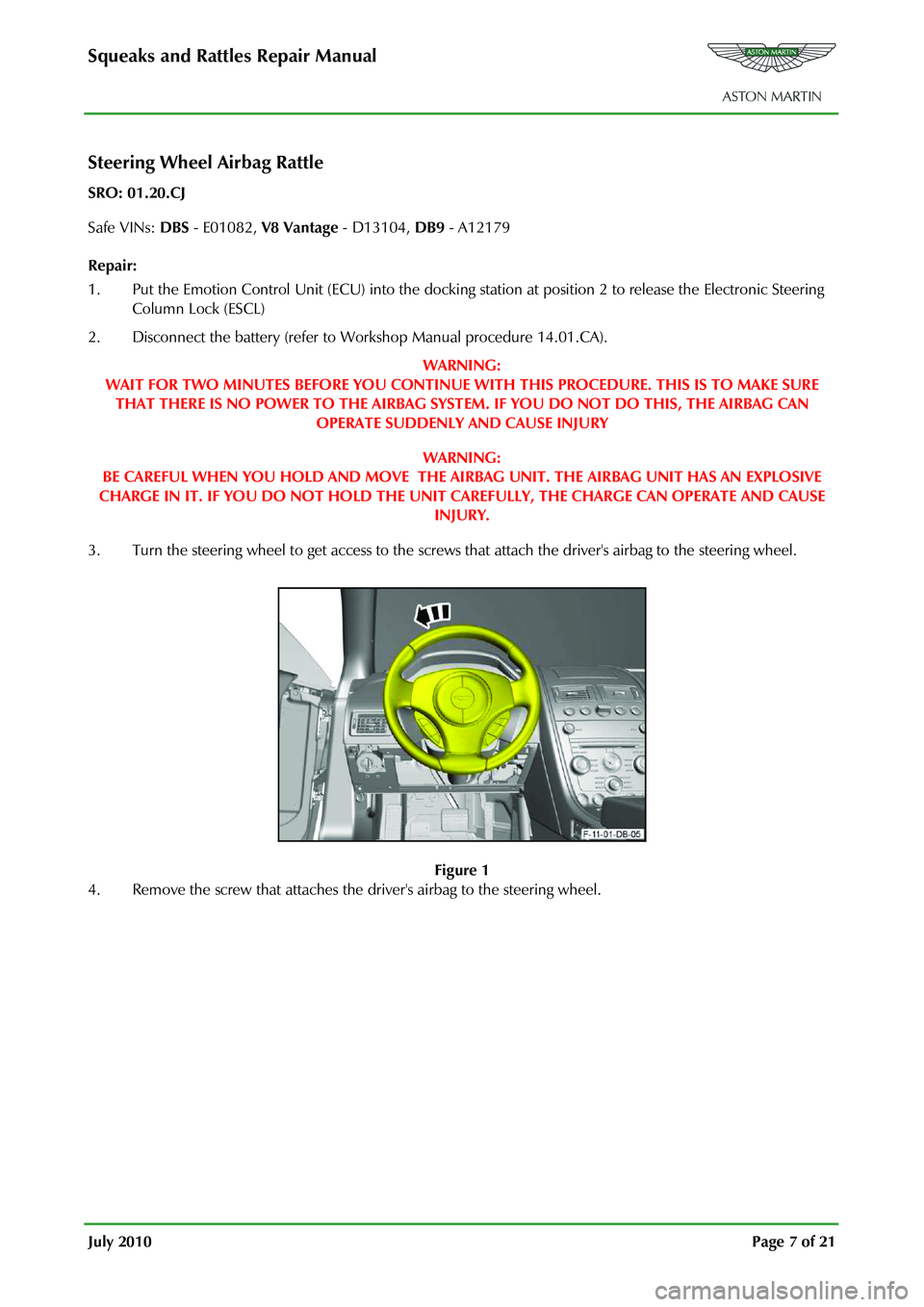
3. Turn the steering wheel to get access to the screws that attach the driver's airbag to the steering wheel.
Figure 1
4. Remove the screw that attaches the driver's airbag to the steering wheel.