steering wheel ASTON MARTIN V8 VANTAGE 2010 User Guide
[x] Cancel search | Manufacturer: ASTON MARTIN, Model Year: 2010, Model line: V8 VANTAGE, Model: ASTON MARTIN V8 VANTAGE 2010Pages: 947, PDF Size: 43.21 MB
Page 225 of 947
Subframes (02.03)
Frame and Mounting (02.00)
May 2007 Workshop Manual 2-1-3
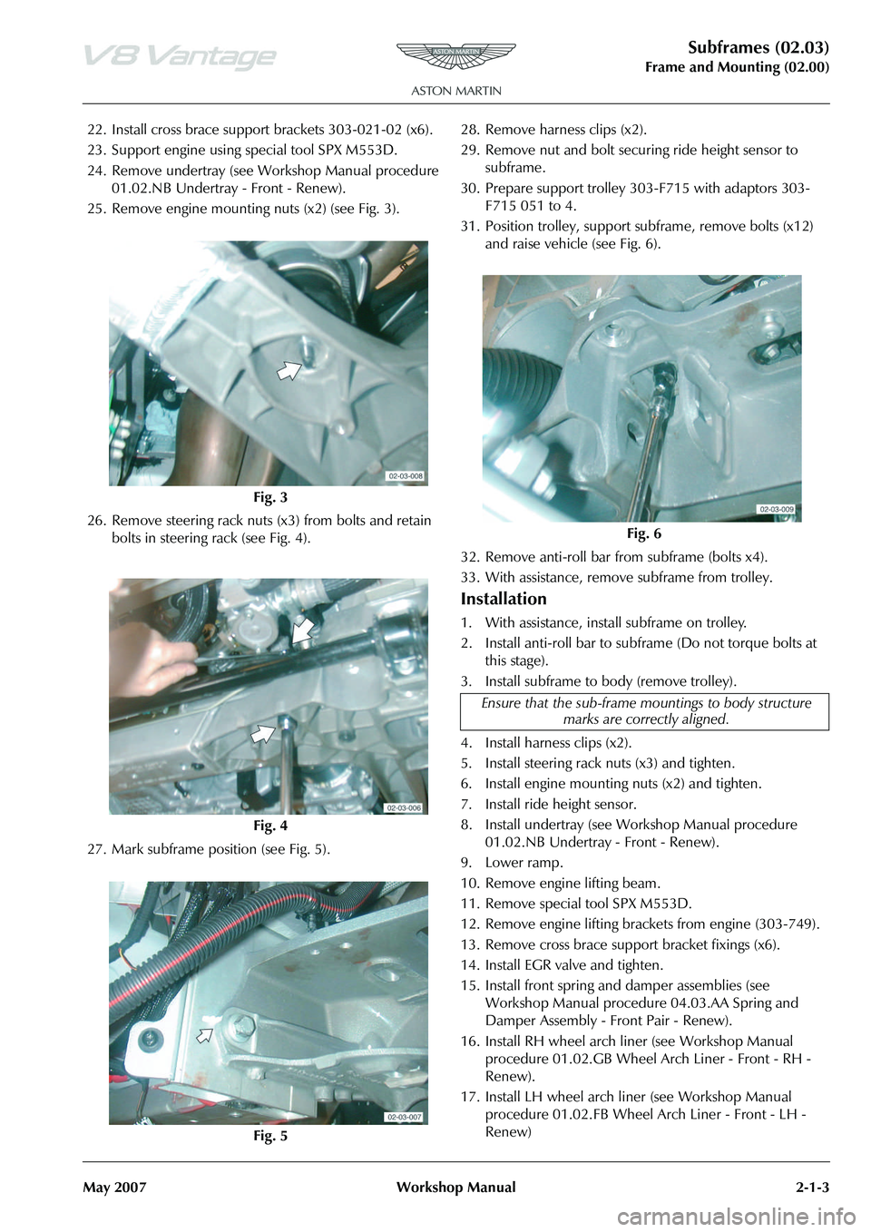
22. Install cross brace support brackets 303-021-02 (x6).
23. Support engine using special tool SPX M553D.
24. Remove undertray (see Workshop Manual procedure 01.02.NB Undertray - Front - Renew).
25. Remove engine mounting nuts (x2) (see Fig. 3).
26. Remove steering rack nuts (x3) from bolts and retain bolts in steering rack (see Fig. 4).
27. Mark subframe position (see Fig. 5). 28. Remove harness clips (x2).
29. Remove nut and bolt securi
ng ride height sensor to
subframe.
30. Prepare support trolley 30 3-F715 with adaptors 303-
F715 051 to 4.
31. Position trolley, support subframe, remove bolts (x12)
and raise vehicle (see Fig. 6).
32. Remove anti-roll bar from subframe (bolts x4).
33. With assistance, remove subframe from trolley.
Installation
1. With assistance, install subframe on trolley.
2. Install anti-roll bar to subframe (Do not torque bolts at this stage).
3. Install subframe to body (remove trolley).
4. Install harness clips (x2).
5. Install steering rack nuts (x3) and tighten.
6. Install engine mounting nuts (x2) and tighten.
7. Install ride height sensor.
8. Install undertray (see Workshop Manual procedure 01.02.NB Undertray - Front - Renew).
9. Lower ramp.
10. Remove engine lifting beam.
11. Remove special tool SPX M553D.
12. Remove engine lifting brack ets from engine (303-749).
13. Remove cross brace suppo rt bracket fixings (x6).
14. Install EGR valve and tighten.
15. Install front spring and damper assemblies (see Workshop Manual procedure 04.03.AA Spring and
Damper Assembly - Front Pair - Renew).
16. Install RH wheel arch li ner (see Workshop Manual
procedure 01.02.GB Wheel Arch Liner - Front - RH -
Renew).
17. Install LH wheel arch liner (see Workshop Manual procedure 01.02.FB Wheel Arch Liner - Front - LH -
Renew)
Fig. 3
Fig. 4
Fig. 5
Fig. 6
Ensure that the sub-frame mo untings to body structure
marks are correctly aligned.
Page 228 of 947
Subframes (02.03)
Frame and Mounting (02.00)
2-1-6 Workshop Manual May 2007
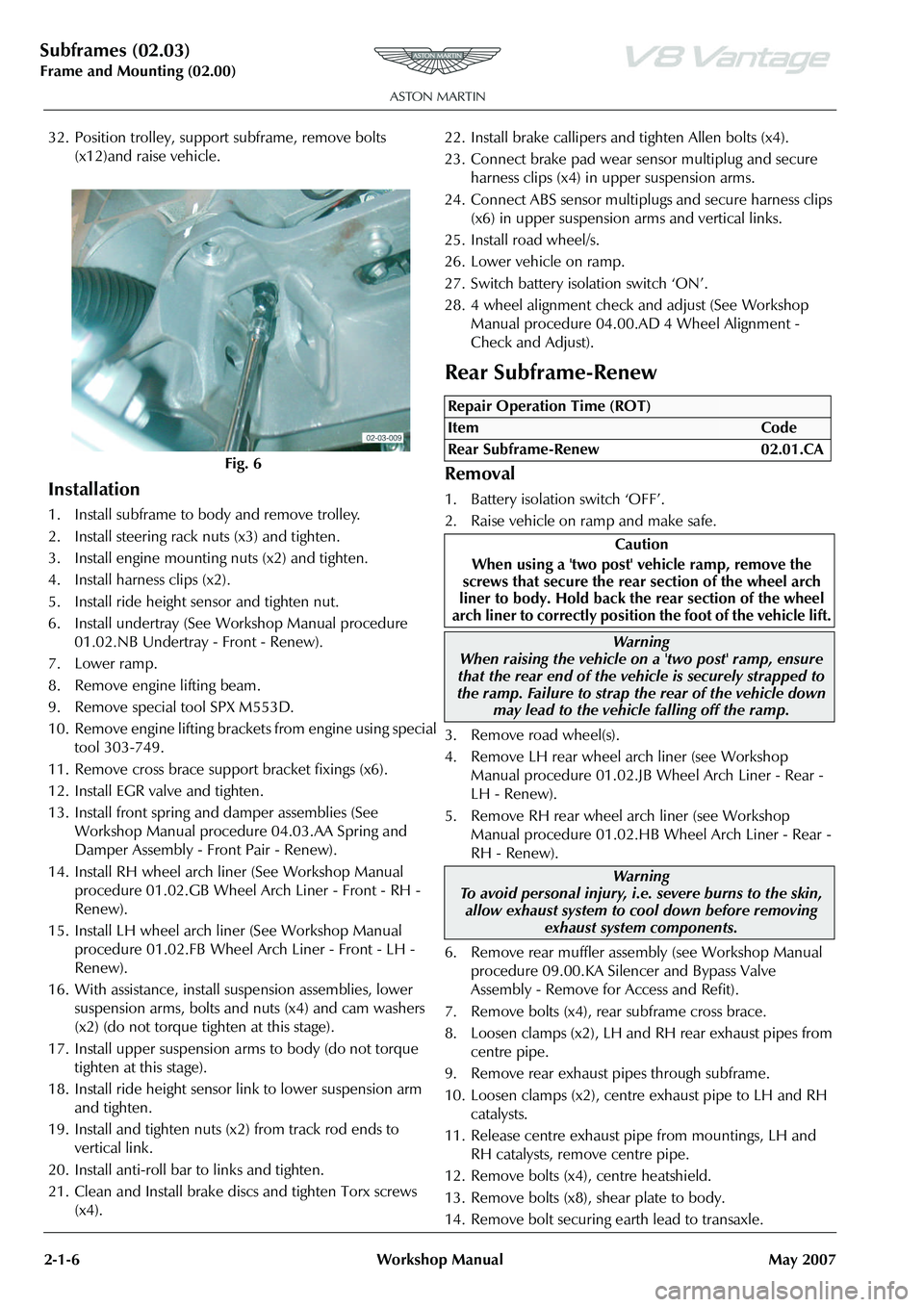
32. Position trolley, support subframe, remove bolts (x12)and raise vehicle.
Installation
1. Install subframe to body and remove trolley.
2. Install steering rack nuts (x3) and tighten.
3. Install engine mounting nuts (x2) and tighten.
4. Install harness clips (x2).
5. Install ride height sensor and tighten nut.
6. Install undertray (See Workshop Manual procedure 01.02.NB Undertray - Front - Renew).
7. Lower ramp.
8. Remove engine lifting beam.
9. Remove special tool SPX M553D.
10. Remove engine lifting bracket s from engine using special
tool 303-749.
11. Remove cross brace support bracket fixings (x6).
12. Install EGR valve and tighten.
13. Install front spring and damper assemblies (See Workshop Manual procedure 04.03.AA Spring and
Damper Assembly - Front Pair - Renew).
14. Install RH wheel arch liner (See Workshop Manual procedure 01.02.GB Wheel Arch Liner - Front - RH -
Renew).
15. Install LH wheel arch liner (See Workshop Manual procedure 01.02.FB Wheel Arch Liner - Front - LH -
Renew).
16. With assistance, install suspension assemblies, lower suspension arms, bolts and nuts (x4) and cam washers
(x2) (do not torque tighten at this stage).
17. Install upper suspension arms to body (do not torque tighten at this stage).
18. Install ride height sensor link to lower suspension arm and tighten.
19. Install and tighten nuts (x2) from track rod ends to vertical link.
20. Install anti-roll bar to links and tighten.
21. Clean and Install brake discs and tighten Torx screws (x4). 22. Install brake callipers and tighten Allen bolts (x4).
23. Connect brake pad wear se
nsor multiplug and secure
harness clips (x4) in upper suspension arms.
24. Connect ABS sensor multiplu gs and secure harness clips
(x6) in upper suspension arms and vertical links.
25. Install road wheel/s.
26. Lower vehicle on ramp.
27. Switch battery isolation switch ‘ON’.
28. 4 wheel alignment check and adjust (See Workshop Manual procedure 04.00.AD 4 Wheel Alignment -
Check and Adjust).
Rear Subframe-Renew
Removal
1. Battery isolation switch ‘OFF’.
2. Raise vehicle on ramp and make safe.
3. Remove road wheel(s).
4. Remove LH rear wheel arch liner (see Workshop Manual procedure 01.02.JB Wheel Arch Liner - Rear -
LH - Renew).
5. Remove RH rear wheel arch liner (see Workshop Manual procedure 01.02.HB Wheel Arch Liner - Rear -
RH - Renew).
6. Remove rear muffler asse mbly (see Workshop Manual
procedure 09.00.KA Silencer and Bypass Valve
Assembly - Remove for Access and Refit).
7. Remove bolts (x4), rear subframe cross brace.
8. Loosen clamps (x2), LH and RH rear exhaust pipes from
centre pipe.
9. Remove rear exhaust pipes through subframe.
10. Loosen clamps (x2), centre exhaust pipe to LH and RH
catalysts.
11. Release centre exhaust pipe from mountings, LH and RH catalysts, remove centre pipe.
12. Remove bolts (x4), centre heatshield.
13. Remove bolts (x8), shear plate to body.
14. Remove bolt securing earth lead to transaxle.
Fig. 6
Repair Operation Time (ROT)
ItemCode
Rear Subframe-Renew 02.01.CA
Caution
When using a 'two post' vehicle ramp, remove the
screws that secure the rear section of the wheel arch
liner to body. Hold back the rear section of the wheel
arch liner to correctly position the foot of the vehicle lift.
Warning
When raising the vehicle on a 'two post' ramp, ensure
that the rear end of the vehi cle is securely strapped to
the ramp. Failure to strap th e rear of the vehicle down
may lead to the vehicl e falling off the ramp.
Warning
To avoid personal injury, i.e. severe burns to the skin, allow exhaust system to cool down before removing
exhaust system components.
Page 301 of 947
Cooling System (03.03)
Engine (03.00)
Issue 5, Janauary 2010 Workshop Manual 3-3-7
5. Raise expansion tank sufficient to disconnect multiplug, release clip, disconnect hose.
6. Remove expansion tank.
Install
1. Position expansion tank, connect multiplug , install hose and secure with clip.
2. Install nut and bolt, tighten to correct torque.
3. Install hoses (x3) on expansion tank, secure with clips (x3).
4. Install LH cross brace, inst all bolts (x4) (torque with
vehicle on level ground).
5. Refill expansion tank to correct level with correct
coolant fluid mixture.
6. Clean up any spilled coolant fluid.
Coolant Recovery Tank Assembly -
Remove and Install
Remove
1. Raise the vehicle and make it safe.
2. On Roadster vehicles, re move the centre undertray.
3. Remove the left side front wheel.
4. Remove the five or six M6 Torx-head screws that attach the rear of the wheelarch liner.
5. Remove the self-tapping screw that attaches the rear of the wheelarch liner into the wheelarch.
6. Turn the steering fully to the left.
7. Move the rear of the wheela rch liner away to get access
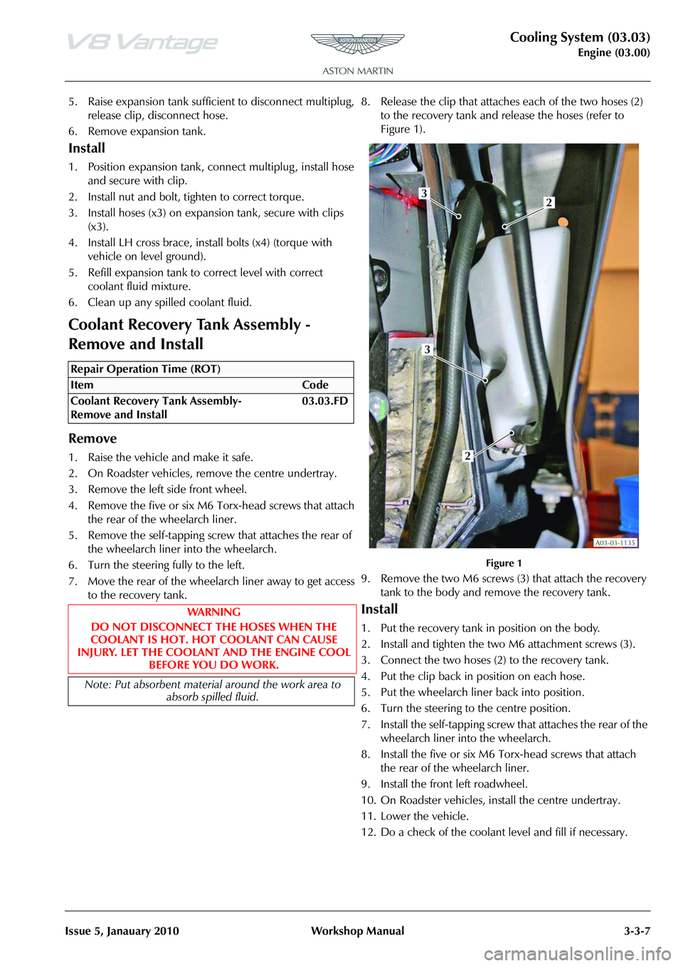
to the recovery tank. 8. Release the clip that attaches each of the two hoses (2)
to the recovery tank and release the hoses (refer to
Figure 1).
Figure 1
9. Remove the two M6 screws (3) that attach the recovery tank to the body and remove the recovery tank.
Install
1. Put the recovery tank in position on the body.
2. Install and tighten the two M6 attachment screws (3).
3. Connect the two hoses (2) to the recovery tank.
4. Put the clip back in position on each hose.
5. Put the wheelarch liner back into position.
6. Turn the steering to the centre position.
7. Install the self-tapping screw that attaches the rear of the wheelarch liner into the wheelarch.
8. Install the five or six M6 Torx-head screws that attach the rear of the wheelarch liner.
9. Install the front left roadwheel.
10. On Roadster vehicles, install the centre undertray.
11. Lower the vehicle.
12. Do a check of the coolant level and fill if necessary.
Repair Operation Time (ROT)
Page 419 of 947
Engine Management System (03.14)
Engine (03.00)
Issue 5, Janauary 2010 Workshop Manual 3-14-3
Removal
1. Raise vehicle on ramp.
2. Remove rear exhaust silencer (refer to Workshop Manual procedure 09.00.KA Silencer and Bypass Valve
Assembly - Remove for Access and Refit).
3. Disconnect multiplugs (x2), HEGO sensors.
4. Secure sufficient lengths of string to HEGO sensor multiplugs for assembly purposes.
5. Loosen LH and RH clamp nuts, catalysts to centre pipes.
6. With assistance, manoeuvre exhaust centre pipe assembly rearwards to release from catalysts.
7. Remove nuts (x3), catalyst to exhaust manifold.
8. Release and support weight of LH catalyst from exhaust manifold.
9. Manoeuvre HEGO sensor leads and remove cable tie. Release HEGO sensor leads from behind heat shield.
Remove string from HEGO multiplugs.
10. Remove catalyst assembly.
11. Remove and discard gasket.
12. Remove HEGO sensors from catalyst.
Installation
1. Clean catalyst, mating joint faces and HEGO sensors.
2. Install and tighten HEGO sensor to catalyst.
3. Apply proprietary exhaust se alant around clamp joints.
4. Install new gasket to exhaust manifold.
5. Position catalyst, secure string (x2) to HEGO multiplugs, feed sensor leads behind heat shield. Install catalyst to
exhaust manifold.
6. Instal land tighten nuts (x3), catalyst to exhaust manifold.
7. Align centre pipe assembly to catalyst, tighten clamp
nuts to.
8. Remove string (x2), conne ct multiplugs (x2), HEGO
sensors.
9. Install rear exhaust silencer (refer to Workshop Manual procedure 09.00.KA Silencer and Bypass Valve
Assembly - Remove for Access and Refit).
10. Lower vehicle on ramp.
Left Side Powertrain Control Module
(PCM) (Coupe Only) - Remove and
Install
Remove
1. Disconnect the ba ttery ground cable.
2. Remove the wheel and tyre. (refer to Workshop Manual procedure 04.04.EC - Wheel and Tyre)
3. Remove the six rear screws that attach the wheel-arch liner to the body.
4. Remove the rear screw that attaches the wheel-arch liner to the body.
5. Turn the steering fully to the right.
6. Move the wheel arch liner to get access to the Powertrain Control Module (PCM).
7. Disconnect the electrical connector from the direction
indicator.
8. Release the four fi r-tree clips that attach the wiring
harness for the direction indi cator and the screen wash
system.
9. Release the two fir tree clips that attach the wiring harness for the PCM.
10. Remove the three bolts that attach the PCM bottom bracket and PCM to the PCM top bracket.
11. Disconnect the three electrical connectors from the PCM.
12. Remove the PCM.
Install
1. Put the PCM in position.
2. Connect the three electrical connectors to the PCM.
3. Align the PCM to the top bracket.
4. Align the bottom bracket to the PCM.
5. Install and tighten the three bolts that attach the PCM bottom bracket and PCM to the PCM top bracket.
6. Install the two fir tree clips that attach the wiring harness for the PCM.
7. Attach the four fir-tree cl ips that attach the wiring
harness for the direction indi cator and the screen wash
system.
8. Connect the electrical connector to the direction indicator.
9. Put the wheel-arch liner into the correct position.
10. Install and tighten the rear screw that attaches the wheel-arch liner to the body.
11. Install and tighten the six rear screws that attach the wheel-arch liner to the body.
12. Move the steering to the centre position.
13. Connect the battery ground cable.
14. Install the wheel and tyre. (04.04.EC - Wheel and Tyre)
15. Connect AMDS.
16. Use AMDS to do a test of the PCM. (00.06.AD - AMDS Operation Check)
WA R N I N G
THE EXHAUST SYSTEM WILL BE VERY HOT AFTER OPERATION. LET THE EXHAUST SYSTEM COOL
BEFORE YOU DO WORK. IF YOU DO NOT, SEVERE
INJURY CAN OCCUR
Repair Operation Time (ROT)
Page 420 of 947

Engine Management System (03.14)
Engine (03.00)3-14-4 Workshop Manual Issue 5, Janauary 2010
Left Side Powertrain Control Module
(PCM) (Roadster Only) - Remove and
Install
Remove
1. Disconnect the battery ground cable.
2. Lift the vehicle on a four-post lift.
3. Remove the centre undertray. (refer to Workshop Manual procedure 01.02.MB - Centre Undertray)
4. Lower the vehicle.
5. Lift the vehicle on a two-post lift.
6. Remove the wheel and tyre. (refer to Workshop Manual procedure 04.04.EC - Wheel and Tyre)
7. Remove the six rear screws that attach the wheel-arch liner to the body.
8. Remove the rear screw that attaches the wheel-arch liner to the body.
9. Turn the steering fully to the right.
10. Move the wheel-arch liner to get access to the Powertrain Control Module (PCM).
11. Disconnect the electrical connector from the direction indicator.
12. Release the four fir tree cl ips that attach the wiring
harness for the direction indicator and the screen wash
system.
13. Release the two fir tree clips that attach the wiring harness for the PCM.
14. Remove the three screws that attach the PCM bottom bracket and PCM to the PCM top bracket.
15. Disconnect the three elec trical connectors from the
PCM.
16. Remove the PCM.
Install
1. Put the PCM in position.
2. Connect the three electrical connectors to the PCM.
3. Align the PCM with the top bracket.
4. Align the bottom bracket with the PCM.
5. Install and tighten the three screws that attach the PCM bottom bracket and PCM to the PCM top bracket.
6. Install the two fir tree clips that attach the wiring harness for the PCM.
7. Attach the four fir tree clips that attach the wiring harness for the indicator and the screen wash system.
8. Connect the electrical connector to the indicator.
9. Put the wheel-arch liner into the correct position.
10. Install and tighten the rear screw that attaches the wheel-arch liner to the body. 11. Install and tighten the six rear screws that attach the
wheel-arch liner to the body.
12. Install the centre undertray. (refer to Workshop Manual procedure 01.02.MB - Centre Undertray)
13. Install the wheel and tyre. (refer to Workshop Manual procedure 04.04.EC - Wheel and Tyre)
14. Move the steering to the centre position.
15. Connect the battery ground cable.
Repair Operation Time (ROT)
Page 427 of 947

Front Suspension (04.01)
Suspension (04.00)
November 2008 Workshop Manual 4-1-1
Suspension (04.00)
Front Suspension (04.01)
Description
Suspension Arms
The upper suspension arm is attached to the body structure.
The lower suspension arm is attached to the front subframe.
Each upper suspension arm has a press-fit ball-joint, and two
interleaved rubber bushes. Two bolts attach the upper
suspension arm to the body structure.
Each lower suspension arm has a press fit ball-joint and
metal-to-rubber bonded bushes which are attached to the
front subframe by two eccentric cam bolts (Camber and
castor settings).
Anti-roll Bar
The anti-roll bar, is attached to the subframe in two positions
by rubber bushes and clamps. The outer ends of the anti-roll
bar are attached to the lower suspension arms by drop links.
The anti-roll bar provides the required stiffness to control
body roll.
Vertical link
The Vertical link (Knuckle Joint) swivels on the upper and
lower suspension arms via ball-joints, and carries the hub, a
unit 3 wheel bearing (including the ABS encoder ring), the
wheel speed sensor, the brake caliper, and the brake disc
and shield. The position of the Vertical link is determined by
the movement of the steering rack, which is connected to
the Vertical link by the steering track rod.
Specifications
Upper Arm Ball Joint
and Bushes
Ball Joint
and Bushes Verticle
Link
Bolts to Body
Lower Arm
Anti-roll Bar Drop Links
Eccentric
Cam Bolts
04-01-003
Torque Figures
DescriptionNmlb. / ft.
Brake dust shield. 9 7
Bearing Assembly to the Vertical
link. 55 41
Vertical Link to the Lower
Suspension Arm. 90 66.5
Vertical Link to the Upper
Suspension Arm. 90 66.5
Track-rod End Lock Nut. 70 52
Vehicle Ride Height Sensor. M8 M522.5
9 17
7
Anti-roll Bar Link Nuts 110 81.5
Anti-roll Bar Mounting Bolts
Torque bolt 1, then bolt 2, then
bolt 1 again (to allow for rubber
compression) 22.5 17
Torque the following suspensi on fixings with the vehicle
at normal ride height
Lower Suspension Arm front
bush to the Subframe M14 185 137
Lower Suspension Arm rear
bush to the Subframe. M12 115 85
Upper Suspension Arm to the
Front Structure 115 85
Spring and Damper Bolts Top Lower22.5
175 17
129.5
Normal ride height 2 x 37.5kg in front seats (37.5kg in
each seat) plus a full fuel tank.
Page 428 of 947

Front Suspension (04.01)
Suspension (04.00)4-1-2 Workshop Manual November 2008
Symptoms
SymptomPossible CauseAction
Crabbing Front or rear suspension components/road
wheel alignment Inspect front and rear suspension systems.
Check / adjust road wheel alignment
Drive axle damaged New drive axle.
Front ‘Bottoming’
or Riding Low Spring(s)
Dampers Check ride height.
Check dampers.
Drift/Pull Unequal tyre pressure Check / adjust tyre pressures.
Inspect tyre for excessive wear.
Incorrect road wheel alignment Check / adjust road wheel alignment.
Tyres Check / adjust tyre pressu res. Inspect tyre for excessive
wear.
Unevenly loaded or overloaded vehicle Not ify customer of incorrect vehicle loading .
Damaged steering components Check steering sy stem for mechanical or hydraulic bias.
Brake drag Check brakes.
Check steering system for mechanical or hydraulic bias.
Rough Ride Spring(s) Check springs.
Shock absorber(s) Check shock absorbers.
Incorrect Tyre
Wear Incorrect tyre pressure Check and adju
st tyre pressure. Inspect tyre for
excessive wear.
Excessive front or rear Toe (rapid inner or
outer edge wear) Check and adjust road wheel alignment (Refer to ’Road
Wheel Alignment (04.00)’, page 4-0-2).
Excessive negative or positive camber
(rapid or outer edge wear) Check and adjust road wheel alignment (Refer to ’Road
Wheel Alignment (04.00)’, page 4-0-2).
Tyres out of balance (tyres cupped or
dished) Balance tyres.
‘Shimmy’ or ‘Road
Wheel Tramp’ Loose road wheel nut(s) Check and tighten road wheel nuts to specification.
Loose front suspension Check and tighten
suspension fixings to specification.
Front road wheel bearing(s) Check road wheel bearings.
Road wheel / tyres Check road wheels / tyres.
Shock absorber(s) Check shock absorbers.
Spring(s) Check springs.
Loose, worn or damaged ball -joint(s) Check ball-joint(s).
Loose, worn or damaged steering
components Check components.
Front road wheel alignment Check and adjust road wheel alignment (Refer to ’Road Wheel Alignment (04.00)’, page 4-0-2).
Worn or damaged suspension bushes Check suspension bushes
Poor ‘Return
ability’ of Steering ball-joints Check ball-joint(s).
Steering components Check for excessive friction in steering system.
Check tyre pressures
Steering Wheel
Off-Centre Unequal front or rear Toe settings Check and adjust road wheel alignment.
Steering components Check and install new components as required.
Sway or Roll Overloaded, unevenly or incorrectly
loaded vehicle Notify customer of incorrect vehicle loading
Loose road wheel nut(s) Check. Tighten road wheel nut(s) to specification
Spring(s) Check. Install new springs as required.
Shock absorber(s) Check. Install new shock absorbers as required.
Loose front stabilizer bar or rear stabilizer
bar Check. Tighten anti-roll bar to specification.
Page 429 of 947
Front Suspension (04.01)
Suspension (04.00)
November 2008 Workshop Manual 4-1-3
Maintenance
RH/LH Front Hub and Bearing Assembly
- Renew
Removal
1. Raise vehicle on ramp.
2. Remove road wheel(s).
3. Release pad wear sensor harness clips (x2) from upper suspension arm.
4. Disconnect multiplug from wheel speed sensor.
5. Ease caliper pistons to release pads.
6. Remove caliper Allen bolts (x2), release caliper and tie
aside.
7. Remove retaining screws (x2) and disc.
8. Remove Torx securing wheel speed sensor to vertical link, remove sensor.
9. Remove Allen bolts (x4) securing hub bearing assembly to vertical link. 10. Release/remove hub bearing assembly from vertical link.
Installation
1. Clean hub bearing carrier and mating face on vertical
link.
2. Install hub bearing assembly, install and torque tighten Allen bolts (x4).
3. Clean wheel speed sensor.
4. Install wheel speed sensor, install and torque tighten Torx screw.
5. Clean disc.
6. Install disc, install and torque tighten retaining screws (x2).
7. Connect multiplug to wheel speed sensor.
8. Install caliper, install and to rque tighten Allen bolts (x2).
9. Install pad wear sensor harness clips (x2) in upper suspension arm.
10. Pump brake pedal.
11. Install road wheel(s).
12. Lower vehicle on ramp.
Vibration/Noise
Tyres/road wheel
Road wheel bearing assemblies
Brake components
Suspension components
Spring and damper units
Steering components Check. Install new components as required.
Vehicle Leans to
One Side Unevenly loaded or overloaded vehicle Notif
y customer of incorrect vehicle loading .
Front or rear suspension components Inspect front and rear suspension systems.
Spring and damper assemblies Check spring and damper assemblies.
Incorrect ride height. Lateral tilt out of
specification
Suspension bushes not torqued at ride
height Check ride height.
Check / adjust suspension bushes torque.
Wander Unevenly loaded or overloaded vehicle Notif y customer of incorrect vehicle loading .
ball-joint(s) Check ball-joint(s).
Front road wheel bearing(s) Check road wheel bearings.
Loose, worn or damaged suspension
components Check suspension components.
Loose suspension fasteners Check and tighten suspension fasteners to specification.
Steering components Check steering components for wear and / or free play.
Road wheel alignment (excessive total
front Toe-out) Check / adjust road wheel alignment
(Refer to ’Road Wheel Alignment (04.00)’, page 4-0-2).
SymptomPossible CauseAction
Caution
Be careful with the suspension components. The
suspension components can be damaged if hit, for example, with a metal faced hammer.
Repair Operation Time (ROT)
Page 455 of 947
Road Wheels and Tyres (04.04)
Suspension (04.00)
May 2007 Workshop Manual 4-4-5
Road Test
A tyre vibration diagnostic proc edure always begins with a road test. The road test and customer interview (if available)
will provide much of the information neede d to find the source of a vibration.
During the road test, drive the vehicle on a road that is smoot h and free of undulations. If vibration is apparent, note and
record the following:
• The speed at which the vibration occurs
• What type of vibration occurs in each speed range
• How the vibration is affected by changes in the following types of vibration-sensitivity:
Torque Sensitive - This means that the condition may be improved or made worse by accelerating, decelerating, coasting,
maintaining a steady vehicle speed or applying engine torque.
Vehicle Speed Sensitive - This means that the vibration always occurs at the same vehicle speed and is not affected by
engine torque, engine speed or the transmission gear selected.
Engine Speed Sensitive - This means that the vibration occurs at varyin g vehicle speeds when a different transmission
gear is selected. It may sometimes be isolated by increasing or decreasing engine speed with the transmission in NEUTRAL
or by stall testing with the transmission in gear. If the condition is engine speed sensitive, the cause is probably not relate d
to the tyres.
If the road test indicates that there is tyre whine, but no sh ake or vibration, the noise originates with the contact between
the tyre and the road surface.
A thumping noise usually means that the tyre has a flat or soft spot making a noise as they slap the roadway. Tyre whine
may be distinguished from axle noise. Tyre whine remains the same over a range of speeds.
Symptoms
SymptomPossible Source(s):Action(s)
Tyres show excess wear on
edge of treads Tyres under-inflated Correct pressure to specification.
Vehicle overloaded Correct as required.
Tyres show excess wear on
edge of treads (having the
correct tyre pressures) Incorrect toe setting Set to specification.
Tyres show excess wear in
center of tread Tyres over-inflated Correct pressure to specification.
Other excessive tyre wear
problems Incorrect tyre pressure Correct pressure to specification.
Incorrect tyre and wheel usage Install correct tyre and wheel combination.
Geometry out of alignm
ent Check and adjust.
Loose, worn or damaged suspension
components Inspect, repair or install new suspension
components as necessary.
Wheel and tyre assembly out of
balance Balance wheel and tyre assembly.
Excessive lateral or radial runout of
wheel or tyre Check, repair or install a new wheel or tyre as
necessary.
Wheel mounting is difficult Incorrect application or mismatched
parts, including wheel studs and wheel
nuts. Corroded, worn or damaged parts Clean or install new parts.
Wobble or shimmy affecting
wheel runout Damaged wheel (eventually damaging
wheel bearings and causing uneven
tyre wear) Inspect wheel rims for damage and runout.
Install a new wheel rim as necessary.
Excessive vibration, rough
steering or severe tyre wear Loose or incorrect attaching parts Tighten or install new parts.
Page 457 of 947
Road Wheels and Tyres (04.04)
Suspension (04.00)
May 2007 Workshop Manual 4-4-7
Repairs
In view of the high performance capability of the vehicle,
damaged tyres should be renewed and not repaired.
Care of Alloy Road Wheels
Aluminium alloy road wheels are covered with a protective
coating. To prevent corrosion it is essential that this coating
is not damaged. When removing or installing tyres only
equipment utilizing spigot or stud hole clamping must be
used. The equipment must not have any moving parts which
contact the road wheel, and ty re levers must not be used.
To clean road wheels use warm soapy water; stubborn stains
can be removed using a soft brush or by using a proprietary
alloy road wheel cleaner.
Road Wheel Alignment
It is important that correct road wheel alignment be
maintained. Misalignment causes tyre tread to be scrubbed
off laterally because the natural direction of the road wheel
differs from that of the vehicle.
A sharp ‘fin’ protrusion on the edge of each pattern rib is a
sure sign of misalignment.
• ‘Fins’ on the inside edges of the pattern ribs, particularly on the nearside tyre, indicate Toe-in.
• ‘Fins’ on the outside edges, particularly on the offside tyre, indicate Toe-out.
With minor misalignment, the ev idence is less noticeable
and sharp pattern edges may be caused by road camber
even when the road wheel alignment is correct. In such
c a s e s i t i s b e t t e r t o m a k e s u r e b y c h e c k i n g w i t h a n a l i g n m e n t
gauge. Road camber affects the direction of the vehicle by
imposing a side thrus t and , if le ft to follow its natural cou rs e,
the vehicle will drift towards its nearside. This is instinctively
corrected by steering towards the road centre and, as a
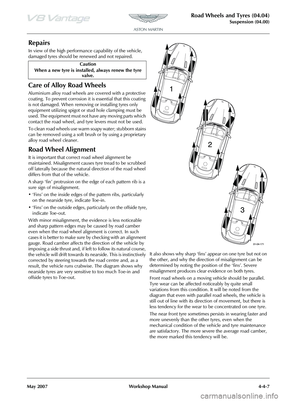
result, the vehicle runs crab wise. The diagram shows why
nearside tyres are very sensitive to too much Toe-in and
offside tyres to Toe-out. It also shows why sharp ‘fins’ appear on one tyre but not on
the other, and why the direction of misalignment can be
determined by noting the position of the ‘fins’. Severe
misalignment produces clea
r evidence on both tyres.
Front road wheels on a moving vehicle should be parallel.
Tyre wear can be affected noticeably by quite small
variations from this condition. It will be noted from the
diagram that even with parallel road wheels, the vehicle is
still out of line with its dire ction of movement, but there is
less tendency for the wear to be concentrated on one tyre.
The near front tyre sometimes persists in wearing faster and
more unevenly than the other tyres, even when the
mechanical condition of the vehicle and tyre maintenance
are satisfactory. The more severe the average road camber,
the more marked this tendency will be.
Caution
When a new tyre is installe d, always renew the tyre
valve.