display AUDI A3 CABRIOLET 2016 Owners Manual
[x] Cancel search | Manufacturer: AUDI, Model Year: 2016, Model line: A3 CABRIOLET, Model: AUDI A3 CABRIOLET 2016Pages: 272, PDF Size: 67.88 MB
Page 5 of 272
<( co .... N ,.__
N .... 0 ,.__
> co
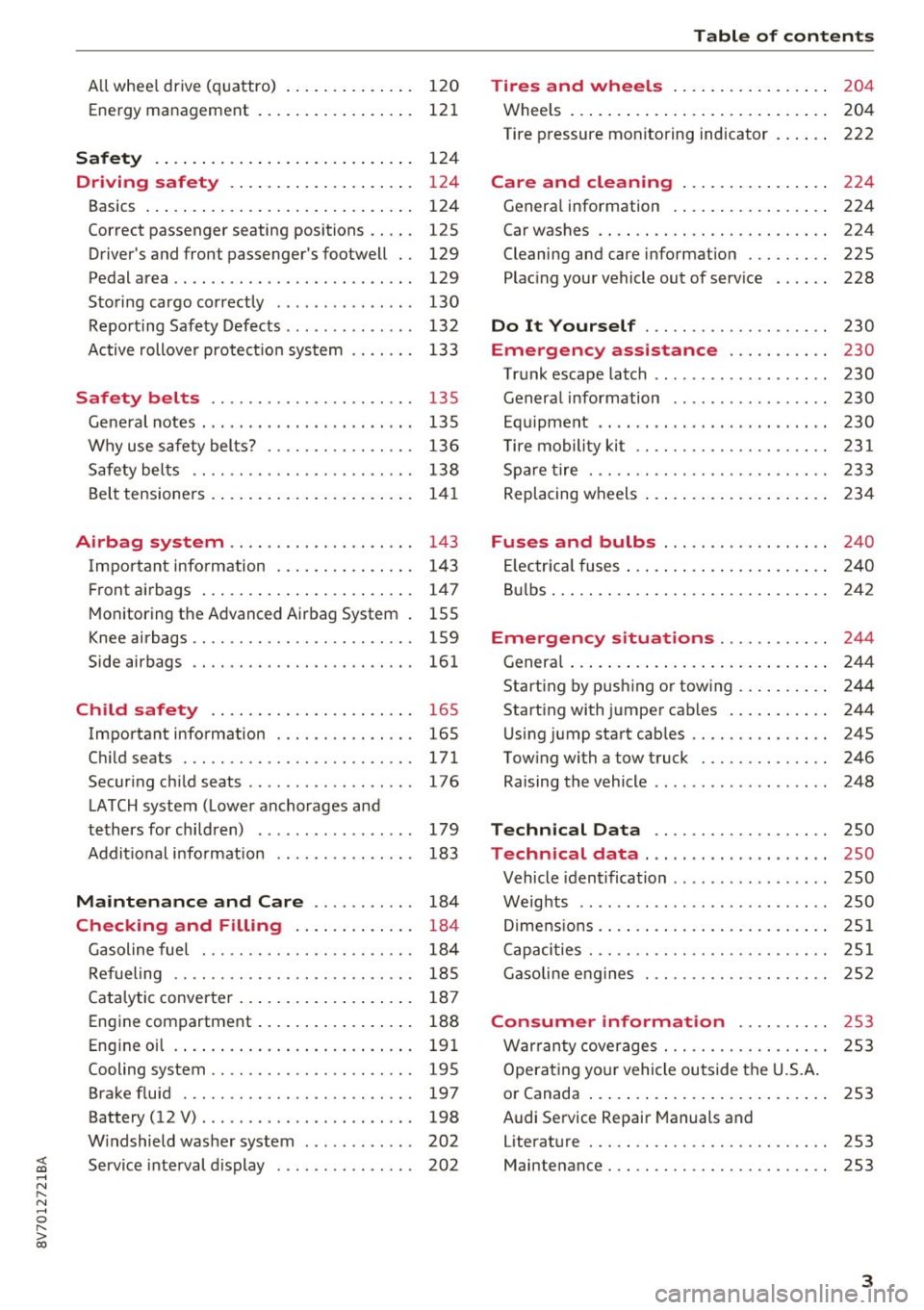
All w hee l drive ( quattro) . . . . . . . . . . . . . . 120
Ene rgy management 121
Safety .. .. .. .. .. .. .... ... .. .. .... . 124
Driving safety . . . . . . . . . . . . . . . . . . . . 124
Basics . . . . . . . . . . . . . . . . . . . . . . . . . . . . . 124
Co rrect p assenge r seating positions . . . . . 125
Driver 's and front passenger 's footwell . . 129
Pedal area . . . . . . . . . . . . . . . . . . . . . . . . . . 129
S toring cargo co rrectly . . . . . . . . . . . . . . . 130
Repo rting Safe ty Defects . . . . . . . . . . . . . . 132
Active rollove r protect io n system 133
Safety belts . . . . . . . . . . . . . . . . . . . . . . 135
Ge neral notes . . . . . . . . . . . . . . . . . . . . . . . 13 5
Why use safety belts? . . . . . . . . . . . . . . . . 136
S afety bel ts . . . . . . . . . . . . . . . . . . . . . . . . 138
B el t tensione rs . . . . . . . . . . . . . . . . . . . . . . 1 41
Airbag system . . . . . . . . . . . . . . . . . . . . 143
I mpor tant info rm ation . . . . . . . . . . . . . . . 14 3
Fr ont airbags . . . . . . . . . . . . . . . . . . . . . . . 1 47
M oni toring th e Advanced Airbag System . 155
K nee airbags . . . . . . . . . . . . . . . . . . . . . . . . 159
Side airbags . . . . . . . . . . . . . . . . . . . . . . . . 161
Child safety . . . . . . . . . . . . . . . . . . . . . . 165
Important info rmation . . . . . . . . . . . . . . . 165
C hi ld seats . . . . . . . . . . . . . . . . . . . . . . . . . 171
Secur ing ch ild seats . . . . . . . . . . . . . . . . . . 176
L ATCH system ( Lowe r anchorages and
tethers for chi ldren) . . . . . . . . . . . . . . . . . 179
Addit io nal i nfo rmat ion . . . . . . . . . . . . . . . 183
Maintenance and Care . . . . . . . . . . . 184
Checking and Filling . . . . . . . . . . . . . 184
G asoline fuel . . . . . . . . . . . . . . . . . . . . . . . 184
Refueling . . . . . . . . . . . . . . . . . . . . . . . . . . 18 5
Cata lytic converter . . . . . . . . . . . . . . . . . . . 187
Eng ine compartment . . . . . . . . . . . . . . . . . 188
Eng in e oi l . . . . . . . . . . . . . . . . . . . . . . . . . . 191
Cooling system . . . . . . . . . . . . . . . . . . . . . . 195
Brake fluid . . . . . . . . . . . . . . . . . . . . . . . . . 197
Battery (12 V) . . . . . . . . . . . . . . . . . . . . . . . 198
W indshield was her system . . . . . . . . . . . . 202
Service inte rval display . . . . . . . . . . . . . . . 202
Table of contents
Tires and wheels . . . . . . . . . . . . . . . . .
204
Whee ls . . . . . . . . . . . . . . . . . . . . . . . . . . . . 204
Tire p ressure monitoring ind icator . . . . . . 222
Care and cleaning . . . . . . . . . . . . . . . . 224
G enera l information . . . . . . . . . . . . . . . . . 224
Car washes . . . . . . . . . . . . . . . . . . . . . . . . . 224
Cleaning and ca re i nformat ion . . . . . . . . . 225
Plac ing you r vehicle out of serv ice . . . . . . 228
Do It Yourself . . . . . . . . . . . . . . . . . . . . 230
Emergency assistance . . . . . . . . . . . 230
T ru nk escape latch . . . . . . . . . . . . . . . . . . . 230
Genera l information . . . . . . . . . . . . . . . . . 230
E q ui pment . . . . . . . . . . . . . . . . . . . . . . . . . 230
T ire mobility kit . . . . . . . . . . . . . . . . . . . . . 231
Sp are tire . . . . . . . . . . . . . . . . . . . . . . . . . . 233
Replacing w heels . . . . . . . . . . . . . . . . . . . . 2 34
Fuses and bulbs . . . . . . . . . . . . . . . . . . 240
El ec trica l fuses . . . . . . . . . . . . . . . . . . . . . . 2 40
B ul bs . . . . . . . . . . . . . . . . . . . . . . . . . . . . . . 2 42
Emergency situations . . . . . . . . . . . . 244
Genera l . . . . . . . . . . . . . . . . . . . . . . . . . . . . 2 44
Starting by p ush ing o r towing . . . . . . . . . . 244
Start ing with jumpe r cab les . . . . . . . . . . . 244
U sing jump sta rt cab les . . . . . . . . . . . . . . . 24S
Tow ing with a tow truck . . . . . . . . . . . . . . 246
Raising the vehicle . . . . . . . . . . . . . . . . . . . 248
Technical Data . . . . . . . . . . . . . . . . . . . 250
Technical data . . . . . . . . . . . . . . . . . . . . 250
Vehicle ident ification . . . . . . . . . . . . . . . . . 250
Weig hts . . . . . . . . . . . . . . . . . . . . . . . . . . . 250
Di mens io ns .. .. . .......... ... ..... .. 251
C apaci ties . . . . . . . . . . . . . . . . . . . . . . . . . . 251
Gasoline e ng ines . . . . . . . . . . . . . . . . . . . . 2S2
Consumer information . . . . . . . . . . 2S3
Warr anty cove rages . . . . . . . . . . . . . . . . . . 253
Operat ing yo ur vehicle outside the U.S.A.
o r Canada . . . . . . . . . . . . . . . . . . . . . . . . . . 253
Audi Se rvice Repair Manuals and
Literat ure . . . . . . . . . . . . . . . . . . . . . . . . . . 253
Maintenance. . . . . . . . . . . . . . . . . . . . . . . . 253
3
Page 11 of 272
<( co .... N r--N .... 0 r--> co
CD
@
®
©
®
®
(J)
®
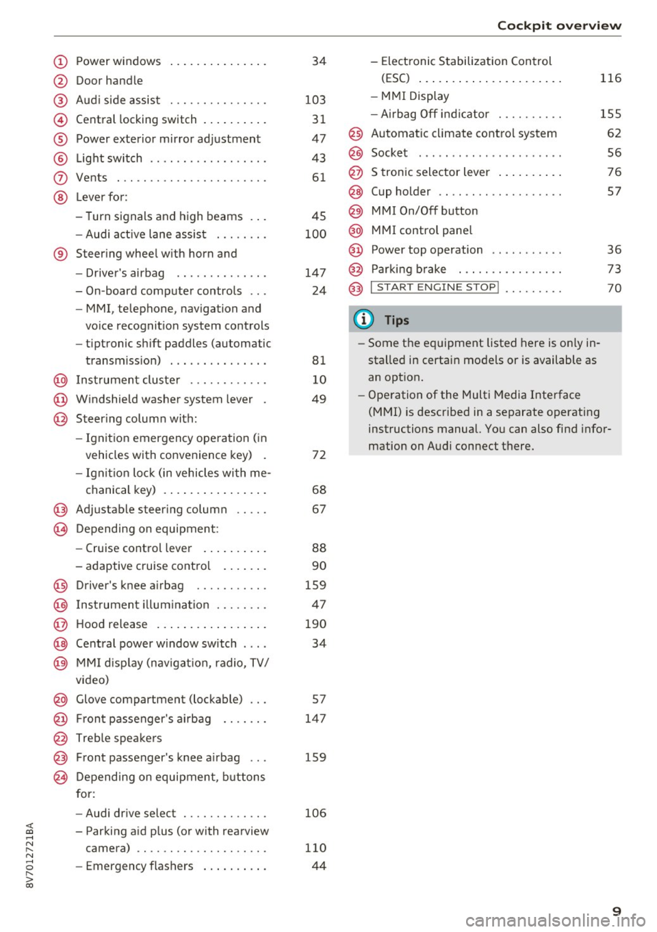
Power windows
Door handle
Aud i side assist ... ......... .. .
Central locking switch .. ... .. .. .
Power exterior mirror ad justment
L ig ht swit ch .... . .......... .. .
Vents
L ever fo r:
- Turn signals and high beams . . .
- Audi a ct ive lane assis t ..... .. .
® Steer ing whee l w ith horn and
- Drive r's airbag ...... ..... .. .
- On-board compute r controls .. .
- MMI, telephone, navigation and
vo ice recognit ion system cont rols
- tiptronic sh ift paddles (automatic
transm iss ion) . .. .... ... .. .. .
@ Ins trumen t cluste r ....... .. .. .
© W indshield washer system lever .
@ Steering column with:
- Ignit ion emergency operation ( in
vehicles with convenience key) .
- Ignit io n lock (in vehicles wi th me - 34
103 3 1
47
43
61
4S
1 0 0
147
24
81 1 0
49
72
chanical key) . . . . . . . . . . . . . . . . 68
@ Adjustable steer ing column
(B) D epending on equipment: 67
- Cruise control leve r . . . . . . . . . . 88
- adaptive cruise contro l . . . . . . . 90
@ Driver's knee a irbag . . . . . . . . . . . 1S9
@ Ins trumen t illum ination . . . . . . . . 47
@ Hood release . . . . . . . . . . . . . . . . . 190
@ Central power w indow sw itch . . . . 34
@ MMI d isp lay (nav igat ion, radio, TV/
video)
@ Glove compartment (lockable) . . . S7
@ Fron t passenger's ai rbag . . . . . . . 147
@ Treble spea ke rs
@ Front passenger's k nee a irbag . . . 159
@ Depending on equipmen t, b utt ons
for:
- Audi dr ive select . . . . . . . . . . . . . 106
- Par king a id p lus (or with rearview
camera) .. ............... .. .
- Emerg ency flashers .. ... .. .. . 110
44
Coc
kpit o ve rv iew
- Elect ronic Stabilization Control
(ESC) ... .. .. .. .... . ..... .. .
- MMI Display
- Ai rbag Off i ndicator ......... .
@ Automatic climate contro l system
@ Socket ..... .. .. ... ......... .
@ S tronic selector lever .. ..... .. .
@ Cup holder .. .. .............. .
@) MM I On/Off button
@ MMI contro l pane l
@ Power top operation . ... ... .. . .
@ Par kin g b rake . .............. .
@) I START ENGINE STOP ! ........ .
(D Tips
- Some the eq uipment listed here is on ly in
sta lled in certai n models or is available as
an opt ion. 116
155
62
56
76
57
36
73
70
- Operation of the Multi Media Inte rface
(MMI) is described in a separate operating
instructions manual. You can also find info r-
mation on A udi connect t here.
9
Page 12 of 272
Instrumen ts and ind icator ligh ts
Instruments and indicator Lights
Instruments
Instrument cluster overview
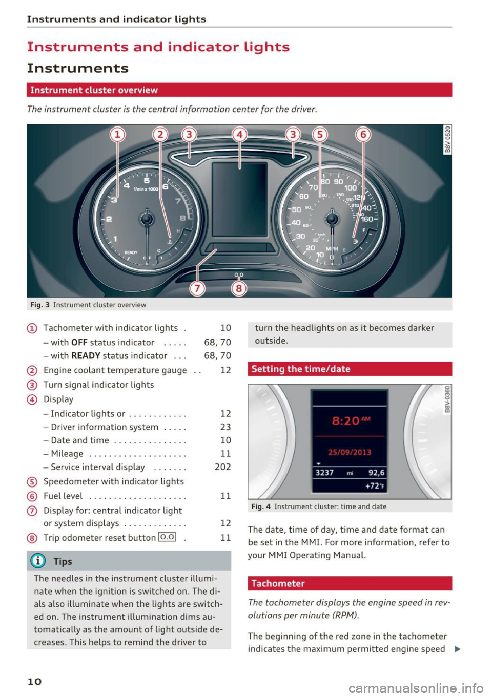
The instrument cluster is the central information center for the driver.
Fig. 3 Instrument cluster overv iew
(D Tachometer with indicator lights
- with
OFF status indicator .... .
- with
RE ADY status indicator .. .
@ Engine coolant temperature gauge
@ Turn signal indicator lights
© Disp lay
- Indicator lights or ...... ... .. . 10
68, 70
68, 70
12
12
- Drive r informat ion system . . . . . 23
- Date and time . . . . . . . . . . . . . . . 10
- Mileage . . . . . . . . . . . . . . . . . . . . 11
- Service interval display . . . . . . . 202
® Speedometer w ith ind icator lights
@ Fue l level ...... ........... .. .
11
0 Display for : centra l indicator light
or system displays ............ . 12
@ Trip odometer reset button 10.01 11
@ Tips
The needles in the instrument cluster illumi
nate when the ignition is switched on . The di
als a lso illuminate when the lights are switch
ed on. The instrument illum ination d ims au
tomatically as the amount of light outside de
creases. T his he lps to remind the dr iver to
10
turn the headlights on as it becomes darker
outside.
Setting the time/date
Fig . 4 Instrument cluster: time and date
The date, time of day, time and date format can
be set in the MMI. For more information, refer to
your MMI Operating Manual.
Tachometer
The tachometer displays the engine speed in rev
olutions per minute (RPM).
The beginning of the red zone in the tachometer
indicates the maximum permitted engine speed .,,_
Page 13 of 272
<( co
for all gears once the engine has been broken in
and when it is warm. You should select the D/S
se lector lever position or take your foot off the
accelerator pedal before reaching th is area .
CD Note
The needle in the tachometer (D c::> page 10,
fig.
3 may only be in the red area of the gauge
for a short time or there is a risk of damaging
the engine.
@ For the sake of the env ironment
Upshifting early helps you to save fuel and re
duce operating noise.
Odometer
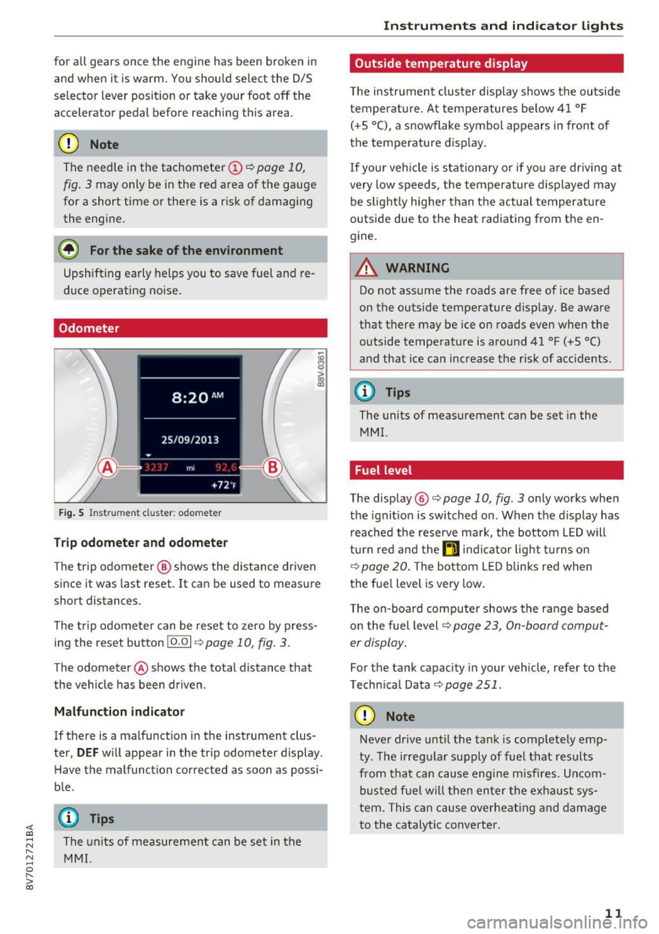
Fig . S In strum ent cl uster : odo meter
Tr ip o dom eter and odom eter
-~ 0
> a, ID
The trip odometer @ shows the distance driven
since it was last reset. It can be used to measure
short distances .
The trip odometer can be reset to zero by press ing the reset button
10.01 c::> page 10, fig. 3.
The odometer @shows the total distance that
the vehicle has been dr iven.
M alfun cti on indic ator
If there is a malfunction in the instrument clus
ter,
DEF w ill appear in the tr ip odometer display .
H ave the malfunction corrected as soon as possi
b le.
@ Tips
;::: The units of measurement can be set in the
" ~ MMI.
0
" > 00
Inst rum ents a nd ind icat or ligh ts
Outside temperature display
The instrument clus ter display shows the outside
temperature. At temperatures below 41 °F
( + 5 °C), a snowflake symbol appears in front of
the temperature display.
If your vehicle is stationary or if you are driv ing at
very low speeds, the temperature d isplayed may
be slight ly higher than the actual temperature
outside due to the heat radiating from the en
gine.
A WARNING
-
Do not assume the roads are free of ice based
on the outside temperature display. Be aware
that there may be ice on roads even when the
outside temperature is around 41 °F
(+5 °()
and that ice can increase the risk of acc idents.
@ Tips
The units of measurement can be set in the
MMI.
Fuel level
The display @c::>page10 , fig. 3 only works when
the ignit ion is switched on . When the display has
reached the rese rve ma rk, the bottom LED will
tu rn red and the
ti ind icator light t urns on
c::>page 20. The bottom LED blinks red when
the fuel level is very low .
The on-board computer shows the range based on the fuel level c::>
page 23, On-board comput
er display.
For the tank capacity in your veh icle, refer to the
Technica l Data
c::> page 251.
CD Note
Never drive until the tank is completely emp
ty . The ir regular supply of fue l that resu lts
from that can cause engine misfires. Uncom
busted fuel w il l then enter the exha ust sys
tem. This can cause overheat ing and damage
to the catalytic converter.
1 1
Page 14 of 272
Instruments and indicator lights
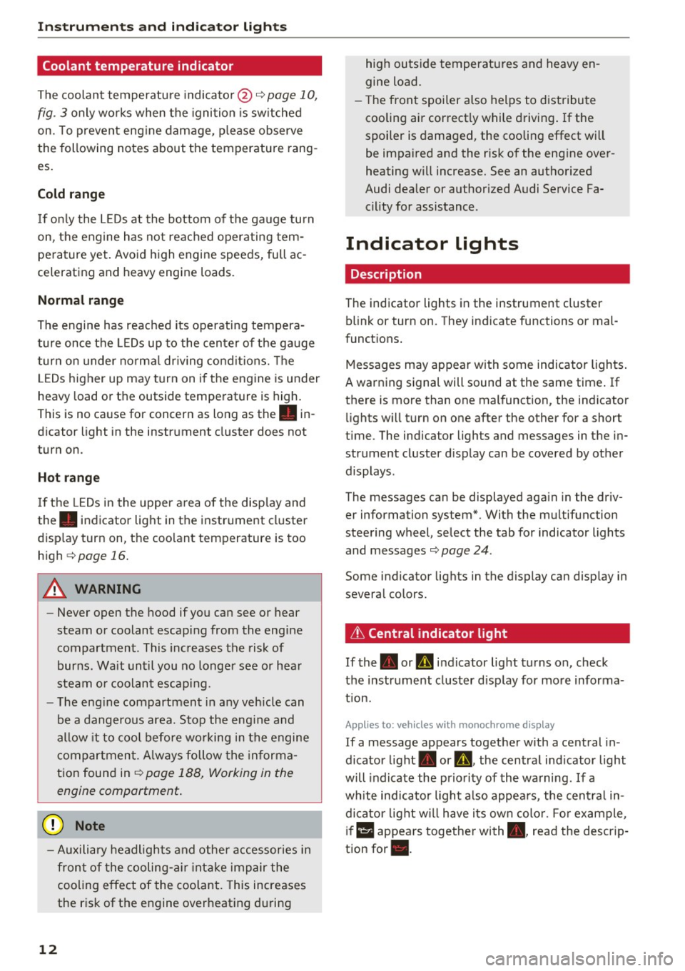
Coolant temperature indicator
The coolant temperature indicator@¢ page 10,
fig . 3
only works when the ignition is switched
on. To prevent engine damage, please observe
the following notes about the temperature rang
es.
Cold range
If only the LEDs at the bottom of the gauge turn
on, the engine has not reached operating tem
perature yet. Avoid high engine speeds, full ac
celerating and heavy engine loads.
Normal range
The engine has reached its operating tempera
ture once the LEDs up to the center of the gauge
turn on under normal driving conditions. The
LEDs higher up may turn on if the engine is under
heavy load or the outside temperature is high.
This is no cause for conc ern as long as the. in
dicator light in the instrument cluster does not
turn on.
Hot range
If the LEDs in the upper area of the display and
the . indicator light in the instrument cluster
display turn on, the coolant temperature is too
high
¢ page 16.
A WARNING
-Never open the hood if you can see or hear
steam or coolant escaping from the engine
compartment. This increases the risk of
burns. Wait until you no longer see or hear
steam or coolant escap ing .
- The engine compartment in any vehicle can
be a dangerous area. Stop the engine and
allow it to cool before working in the engine
compartment. A lways follow the informa
tion found in ¢
page 188, Working in the
engine comportment.
(D Note
- Auxiliary headlights and other accessories in
front of the cooling-air intake impair the
cooling effect of the coolant. This increases
the risk of the engine overheating during
12
high outside temperatures and heavy en
gine load.
- Th e front spoiler also helps to distribute
cooling air correctly while driving. If the
spoiler is damaged, the cooling effect will
be impaired and the risk of the engine over
heating will increase. See an authorized
Audi dealer or authorized Audi Service Fa cility for assistance .
Indicator lights
Description
The indicator lights in the instrument cluster
blink or turn on. They indicate functions or mal
functions.
Messages may appear with some indicator lights.
A warning signal will sound at the same time. If
there is more than one malfunction, the indicator lights will turn on one after the other for a short
time . The indicator lights and messages in the in
strument cluster display can be covered by other
displays .
The messages can be displayed again in the driv
er information system*. With the multifunction
steering wheel, select the tab for indicator lights
and messages
c:> page 24 .
Some indicator lights in the display can display in
several colors.
& Central indicator light
If the . or D indicator light turns on, check
the instrument cluster display for more informa
tion.
App lies to: vehicles wi th mo nochrome disp lay
If a message appears together with a central in
dicator light. or
D. the central indicator light
will indicate the priority of the warning. If a
white indicator light also appears , the central in
dicator light will have its own color . For example,
i'"
@I ::ippears together with., read the descrip
tion for •.
Page 20 of 272
<( co .... N r--N .... 0 r--> co
A WARNING ,~
If the ~ (USA models) /. (Canada mod
els) brake system indicator light turns on to
gether with the ABS and ESC indicator lights,
the ABS/ESC regulat ing funct ion may have
fai led. Functions that stabilize the vehicle are
no longer available. This could cause the vehi
cle to swerve, which increases the risk that
the vehicle will slide. Drive carefully to the
nearest author ized Audi dealer or authorized
Audi Service Facility and have the malfunction corrected.
@ Tips
For additional information on ESC and ABS,
refer to¢
page 116.
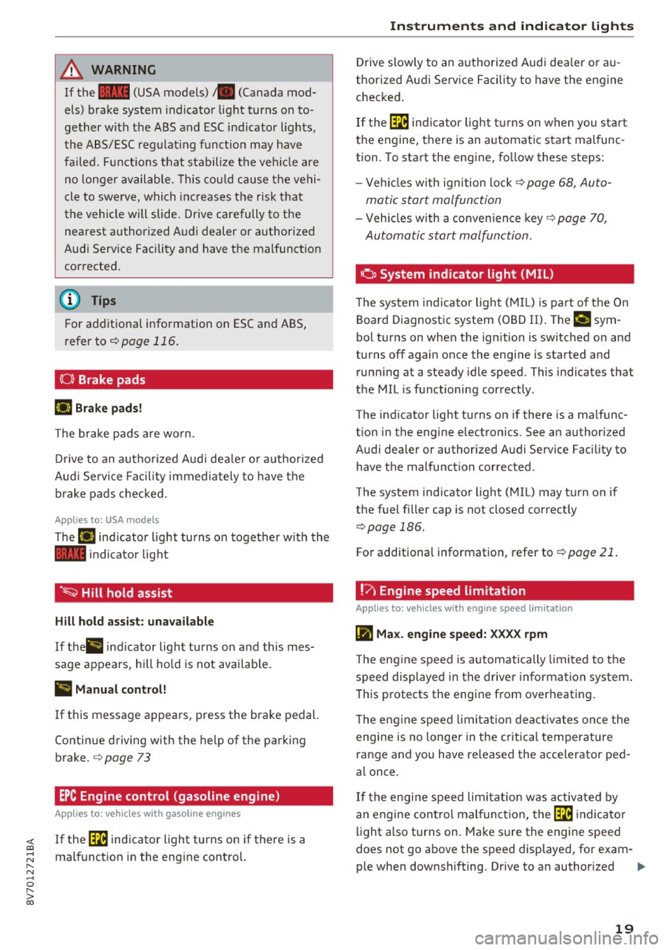
{0} Brake pads
IJ Brake pads!
The brake pads are worn.
Drive to an autho rized Aud i dea le r or authorized
Aud i Service Faci lity immediately to have the
b ra ke pads checked.
Applies to: USA models
The IJ indicator light turns on together with the
~ indicator light
·~ Hill hold assist
Hill hold assist: unavailable
If thP&) indicator light tu rns o n and this mes
sage appears, hill hold is not available.
II Manual control!
If this message appears, press the brake pedal.
Continue driving w ith the help of the park ing
brake. ¢
page 73
EPC Engine control (gasoline engine)
Applies to: veh icles with gasoline engines
If the ~ indicator light turns on if there is a
malfunction in the engine control.
Instruments and indicator lights
Drive slowly to an authorized Audi dea ler or au
thorized Audi Service Facility to have the engine
checked .
If the~ indicator light turns on when you start
the engine, there is an automatic start malfunc
tion. To start the engine, fo llow these steps:
- Vehicles with ignition lock¢
page 68, Auto-
matic start malfunction
- Veh icles with a conve nience key¢ page 70,
Automatic start malfunction.
a System indicator light (MIL)
The system indicator light (MIL) is pa rt of the On
Board Diagnostic system (OBD II) . The
II! sym
bol turns on when the ignition is switched on and
turns off again once the engine is started and
running at a steady idle speed. This indicates that
the MIL is functioning correctly .
The indicator light turns on if there is a malfunc
t ion in the engine electronics . See an authorized
Audi dealer or authorized Audi Service Fac ility to
have the malfunction corrected.
The system indicator light (MIL) may turn on if
the fuel filler cap is not closed correctly
¢ page 186.
For additional information, refer to ¢ page 21.
!? Engine speed limitation
Applies to : vehicles with engine speed limitation
(II Max . engine speed: XXXX rpm
The engine speed is automatically limited to the
speed displayed in the driver information system.
This protects the engine from overheating.
T he eng ine speed limitation deactivates once the
engine is no longer in the critical temperature
range and you have re leased the accelerator ped
al once.
If the engine speed limitation was activated by
an engine control malfunction, the~ indicato r
light also turns on . Make sure the engine speed
does not go above the speed displayed, for exam-
ple when downshifting. Drive to an authorized .,.
19
Page 23 of 272
Instruments and indicator lights
fast acceleration) and have the malfunction cor
rected . See an authorized Audi dealer or
author ized Audi Service Facility .
The indica tor may turn on if the electronic speed
limiter is fau lty. For additional information, refer
to
¢ page 88, Electronic speed limiter .
The MIL may also turn on if the fuel filler cap is
not closed correctly
¢ page 186.
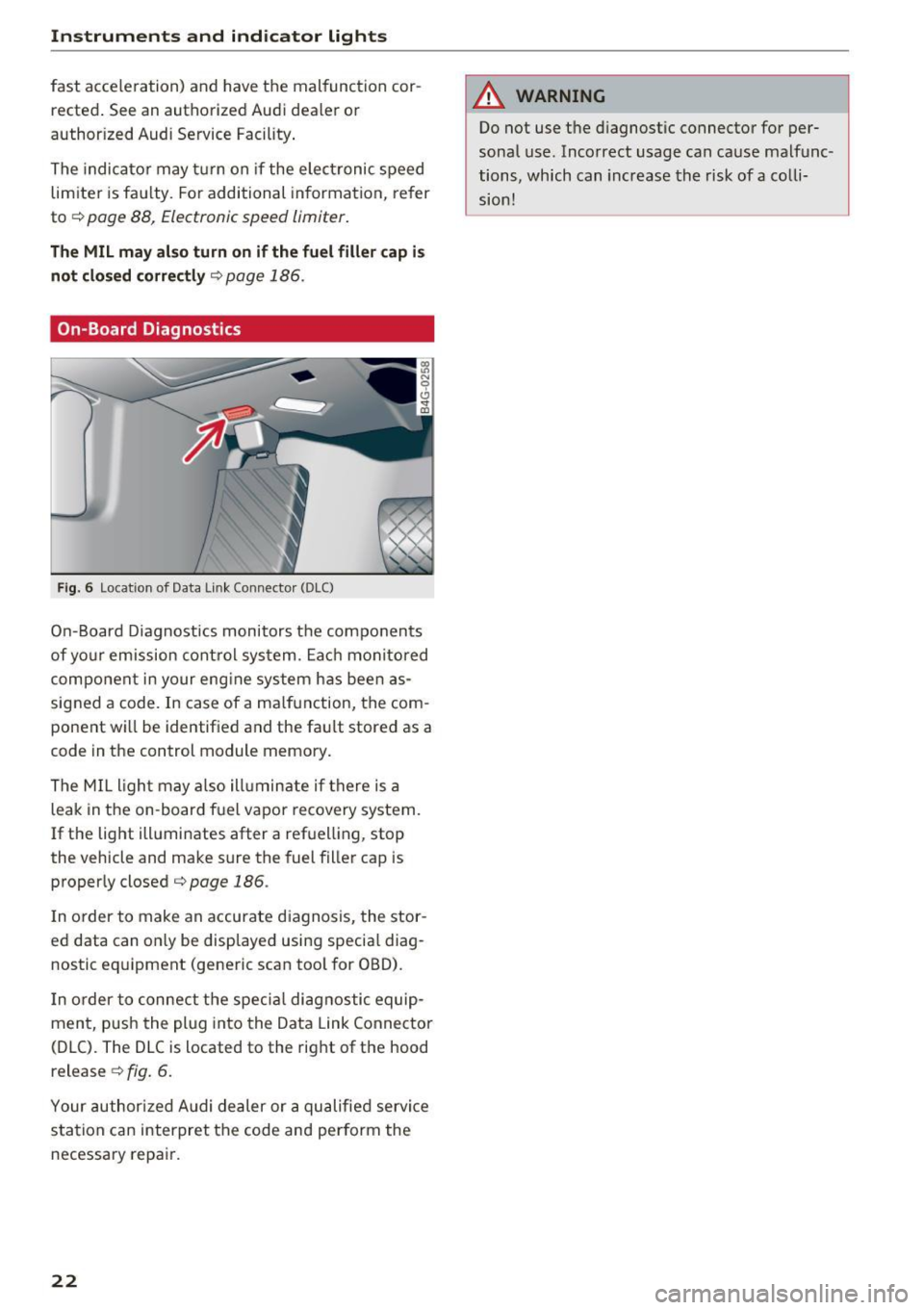
On-Board Diagnostics
F ig. 6 Location of Data Link Connecto r (DLC)
On-Board Diagnostics monitors the components
of yo ur emission control system. Each monitored
component in your eng ine system has been as
signed a code. In case of a ma lfunction, the com
ponent wi ll be identified and the fault stored as a
code in the control module memory.
The MIL light may also ill uminate if there is a
leak in the on -board fuel vapor recovery system.
If the light illuminates after a refuelling, stop
the vehicle and make sure the fuel filler cap is
properly closed¢
page 186.
In order to make an accurate diagnosis, the stor
ed data can on ly be displayed using specia l diag
nostic eq uipment (generic scan tool for OBD).
I n order to connect the specia l diagnostic equip
ment, push the plug into the Data Link Connector
(DLC). The DLC is located to the right of the hood
release ¢
fig. 6.
Your authorized Audi dealer or a qualified servi ce
station can interpret the code and perform the
necessary repair.
22
A WARNING
Do not use t he diagnostic connector for per
sonal use. Incorrect usage can cause malfunc
tions, which can increase the risk
of a colli
sion!
Page 24 of 272
<( co ..... N
" N ..... 0 r--. > 00
Driver information
system
Overview
Applies to: ve hicles with driver information system
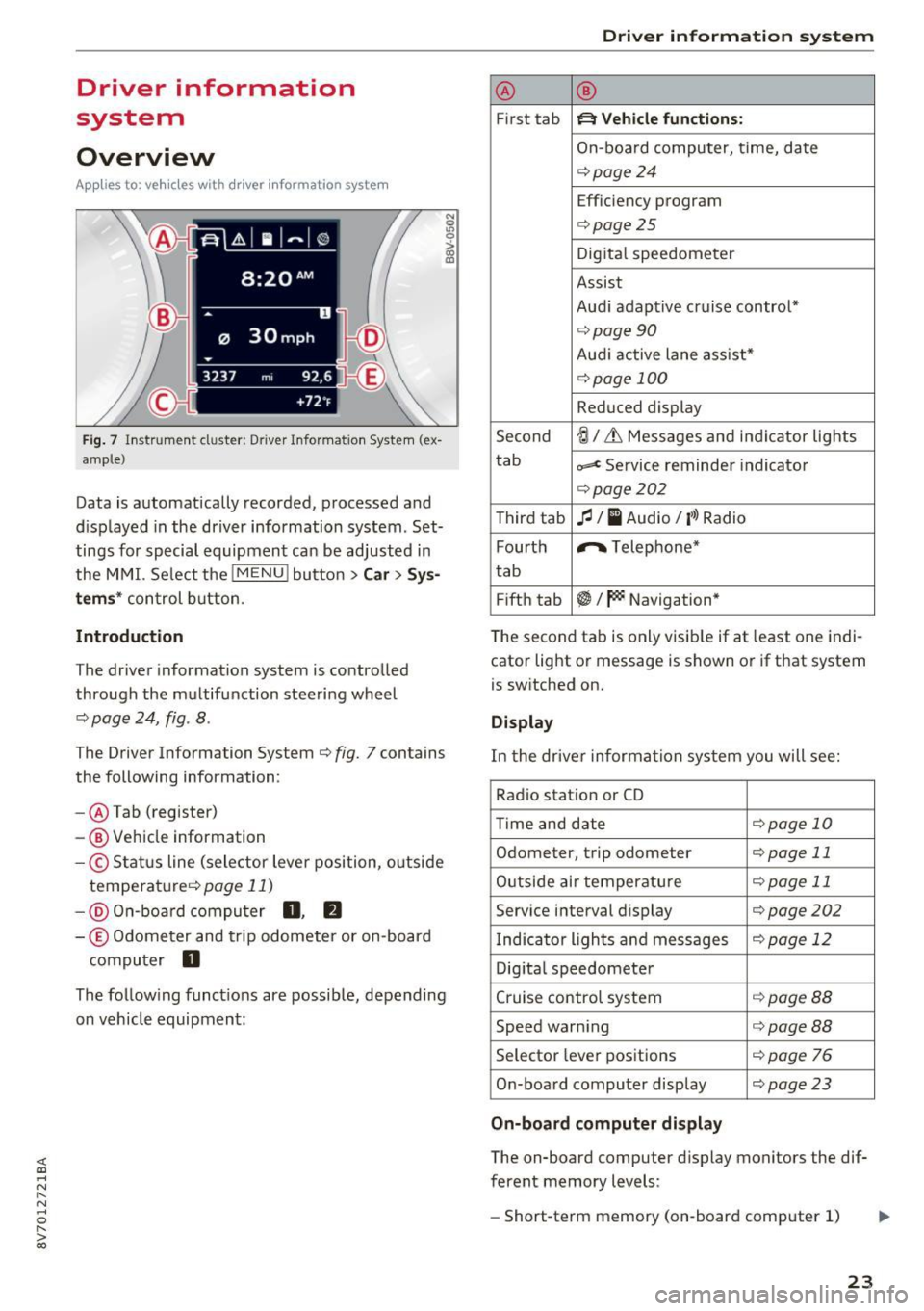
Fig. 7 Instrument cluster : Driver Information System (ex
ample)
Data is automatically recorded, processed and
displayed in the driver information system . Set·
tings for special equipment can be adjusted in
the MMI. Select the
I MENU I button >Car > Sys
tems*
control button.
Introduction
The driver information system is controlled
through the multifunction steering wheel
¢ page 24, fig . 8 .
The Driver Information System ¢ fig. 7 contains
the following information:
- @ Tab (register)
- @ Vehicle information
-© Status line (selector lever position, outside
temperat ure¢ page
11)
-@ On-board computer D , fJ
-© Odometer and trip odometer or on-board
computer
D
The following functions are possible, depending
on vehicle equipment:
Driver in forma tion system
@ ®
First tab ~ Vehicle functions:
On-boa rd computer, time, date
¢page24
Efficiency program
¢page25
Digital speedometer
Assist
Aud i adaptive cruise control*
¢page 90
Audi active lane ass ist*
¢ page 100
Reduced display
Second
ti/ & Messages and indicator lights
tab
c,,,d Service reminder indicator
¢ page202
Third tab fl I I Audio/ I'>) Radio
Fourth ,.,.
Telephone*
tab
Fifth tab
$I~ Navigation*
The second tab is only visible if at least one indi
cator light or message is shown or if that system
is switched on.
Display
In the driver information system you will see:
Radio station or CD
Time and date
¢page 10
Odometer, trip odomete r ¢page 11
Outside air temperature ¢page 11
Service interval display ¢page202
Indicator lights and messages ¢ page 12
Digital speedometer
Cruise control system
¢page BB
Speed warning <=:>page BB
Selector lever positions ¢ page 76
On-board computer display ¢page 23
On-board computer display
The on-board computer display monitors the dif
ferent memory levels :
- Short-term memory (on-board computer 1)
23
Page 25 of 272
Driver information system
-Long-term memory (on-board computer 2)
- Efficiency program
The follow ing information can be displayed con
secutively in the on-board computer:
- Time
- Date
- Estimated range based on current fue l level
- Travel time
- Average consumpt ion
- Average speed
- Distance
- Current fuel consumption
On-board computer
O (short-term memory)
The short-term memory collects driving informa tion from the time the ignition is switched on un
til it is switched off. If you continue driving
with
in two hours
after switching the ignition off, the
new values are included when calculating the cur
rent tr ip informat ion. If stopped for more the
two hours, the short term memory is automati
cally erased once you begin driving.
On-board computer
fl (long-term memory)
Unlike the short-term memory, the long-term
memory is not erased automatically. You can se
lect the time period for evaluating trip informa
tion yourself .
Efficiency program
ii
The efficiency program can help you to use less
fuel
c::;,page 25.
(D Tips
- For information on using the other button
fields, such as the audio, telephone* and
navigation* functions, see the MMI owner's
manual.
- Disconnecting the battery causes all the
memory data to be erased.
24
Operation
Applies to: vehicles wit h driver information system
The driver information system is controlled with
the multifunction steering wheel.
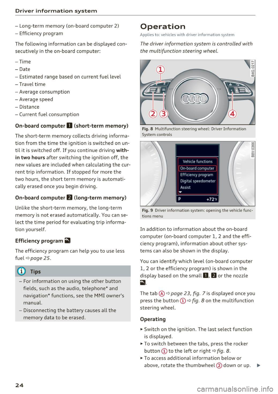
Fig. 8 Mult ifunction steering wheel: Dr iver Info rmation
System controls
Fig. 9 Dr iver infor mation system: open ing the vehicle func
t ions menu
In add it ion to information about the on-board
computer (on-board computer 1 , 2 and the effi
c iency p rogram), informa tion about other sys
tems can also be shown in the display.
You can identify which level (on-board computer
1, 2 or the efficiency program) is shown in the
display based on the small
D, fJ or the nozzle
ii.
The tab@ c::;, page 23, fig. 7 is displayed once yo u
press the button(!)¢
fig. 8 on the multifunct ion
steering wheel.
Operating
"' Switch on the ignition . The last select function
is displayed .
"' To switch between the tabs, press the rocker
button
(D to the left or right c::;, fig. 8.
"'To access additional information below or
above, rotate the thumbwheel @down or up. ""
Page 26 of 272
<( co ..... N
" N ..... 0 r--. > 00
"'To conf irm a sele ction, press the th umbwhee l
@.
"'To select a f unction programmed to a steering
whee l button , press the button @. For addi
tiona l information, see¢
page 25, Assigning
a function to a programmable steering wheel
button
Opening the Vehicle functions
"' Se lect the f irst tab with the button(!).
"' Press the button @. The
Veh icle functions
menu is displayed¢ fig. 9.
"' To select a menu item , turn and press the
t hu mbwheel @.
Resetting values to zero
"'In the Vehicle functions menu, se lect On
board computer or Efficiency program .
"'Select a value in the desired tr ip computer or in
t h e efficiency program .
"'T o reset the va lues in a memory, p ress and ho ld
t h e thu mbw heel @for one secon d.
Recalling indicator lights and messages
"'Press the button CD repeatedly unt il the a tab
appears.
The
a tab is only vis ible when there is a mal
function.
Assigning a function to a programmable s teering wheel button
"' Se lect: the IMENU j button> Car> Systems *
control button > Vehicle settings > Steering
wheel button p rogramming .
The a tab is only visi ble when there is at least
one ind icator light or message displayed .
Driver informa tion system
Efficiency program
Description
Applies to: vehicles with driver information system
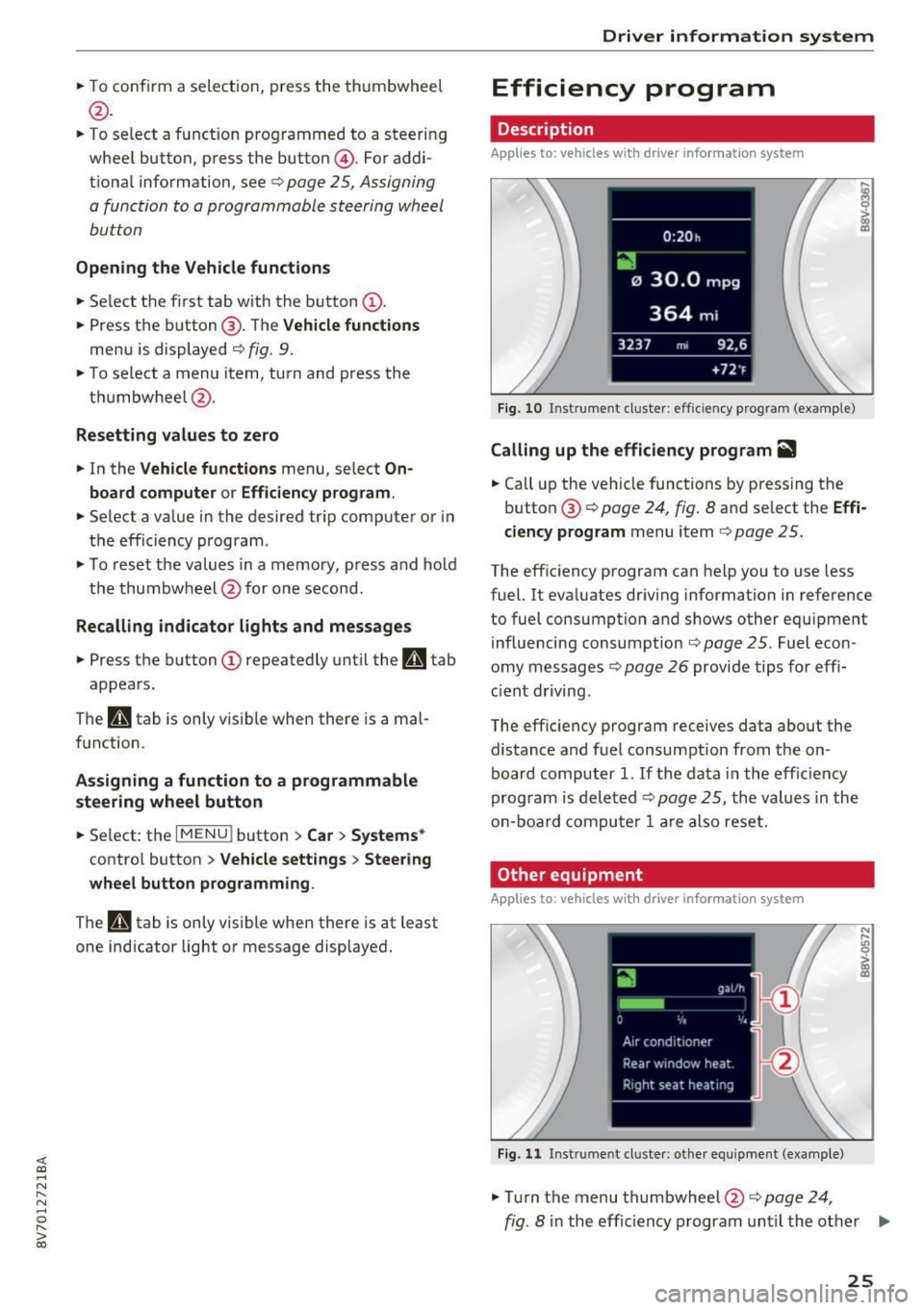
Fig. 10 Inst rume nt cl uste r: eff icie ncy progra m (exa mple)
Calling up the efficiency program ii1
"'Call up the veh icle functions by pressing the
button @¢
page 24, fig . 8 and se lect the Effi
ciency program
menu i tem ¢ page 25.
The eff ic iency program can he lp you to use less
fuel. It eva luates dr iving information in reference
to fuel consumption and shows other equ ipme nt
i nfluencing consumption ¢
page 25. Fuel econ
omy messages ¢
page 26 provide tips for effi
ci ent driving .
The eff ic iency p rogram receives data about the
distance a nd fuel consumpt ion from the on
board computer
1. If t he data i n the eff iciency
program is deleted¢
pag e 25 , the values in the
o n-b oar d co mpu ter 1 ar e als o re se t.
Other equipment
Applies to: vehicles with driver information system
Fig. 11 Inst rume nt cl uste r: other e quipment (exa mple)
"' Tur n the menu th umbwheel @c::> page 24,
N ,..
! m
fig. 8 in the effic iency program unti l the other .,.
25