AUDI A4 AVANT 2008 Owners Manual
Manufacturer: AUDI, Model Year: 2008, Model line: A4 AVANT, Model: AUDI A4 AVANT 2008Pages: 368, PDF Size: 46.19 MB
Page 321 of 368
What do I do now? 11111111
-----------------------------------
& WARNING (continued)
mission in "P" (Park), or engaging a gear in a manual transmission
will
not prevent the vehicle from moving.
• Before you change a wheel, be sure the ground is level and firm.
If necessary, use a sturdy board under the jack.
• After installing the spare wheel, make sure that you remount
the flat tire/wheel in its storage area properly and tighten the
knurled retaining screw securely . •
Changing a wheel
When you change a wheel, follow the sequence described
below step-by-step and exactly in that order.
1. Remove the decorative wheel cover*. For more details
see also
=> page 320, "Decorative wheel covers" or
=> page 320, "Wheels with cap -covered wheel bolts".
2. Loosen the wheel bolts => page 321.
3.
Locate the proper mounting point for the jack and align
the jack below that
point=> page 321.
4. Lift the car with the jack => page 321.
5.
Take the flat wheel off and then put the spare on
=> page 323.
6. Tighten all wheel bolts lightly.
7.
Lower the vehicle with the jack.
8. Use the wheel bolt wrench and
firmly tighten all wheel
bolts=> page 321.
9. Put the decorative wheel cover* back on.
LJ}. WARNING
Always read and head all WARNINGS and information :::::> & in
"Raising the vehicle" on
page 321 and :::::, page 324. •
After changing a wheel
A wheel change is not complete without the following
actions.
-Store and secure the replaced wheel in the spare wheel
well.
-Put the tool case and the jack back in place in the luggage
compartment.
-Check the tire pressure on the spare wheel immediately
after mounting it.
- As soon as possible, have the
tightening torques on all
wheel bolts checked with a torque wrench. The correct
tightening torque is
90 ft lb (120 Nml.
- Have the flat tire
replaced as soon as possible.
[ i] Tips
• If you notice while changing a tire that the wheel bolts are
corroded and difficult to turn, then they should be replaced before
you check the tightening torque.
• Drive at reduced speed until you have the tightening torques
checked .•
Do -it -yourself service
Page 322 of 368
lllffll....__W_ h_ a_ t_d_ o_ l _d _o_ n_ o_ vv_ ? ______________________________________________ _
Applies to vehi cles : wi th deco ra tive wheel co vers
Decorative wheel covers
The decorative wheel covers must be removed first to
access the wheel bolts.
Removing
Fig. 225 Wheel
change : removing the
wheel cover
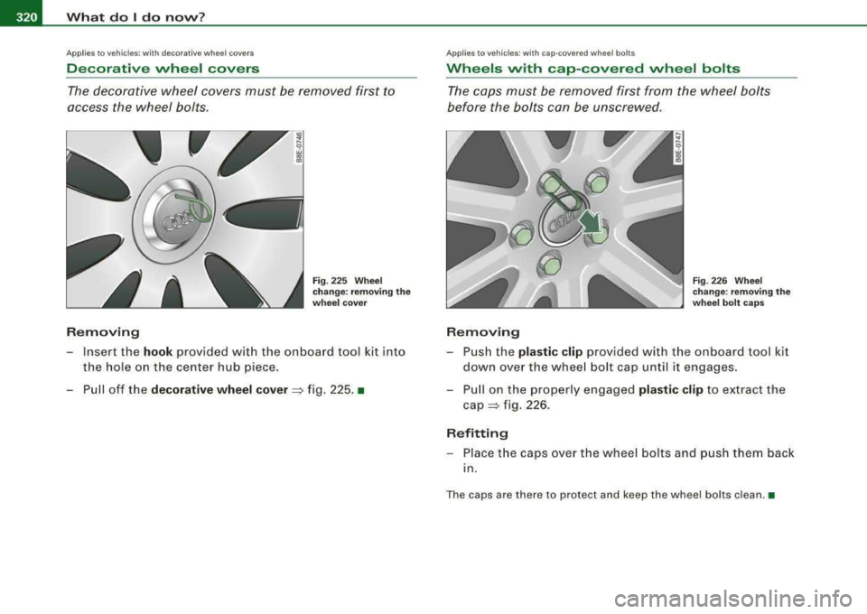
-Insert the hook provided with the onboard tool kit into
the hole on the center hub piece.
-Pull off the decorative wheel cover => fig. 225 . •
App lies to ve hicles: w it h c ap-co vered whee l bolts
Wheels with cap-covered wheel bolts
The caps must be removed first from the wheel bolts
before the bolts can be unscrewed.
Removing
Fig. 226 Wheel
change: removing the
wheel bolt caps
-Push the plastic clip provided with the on board tool kit
down over the wheel bolt cap until it engages.
-Pull on the properly engaged plastic clip to extract the
cap=> fig. 226.
Refitting
-Place the caps over the wheel bolts and push them back
in.
The caps are there to protect and keep the wheel bolts clean. •
Page 323 of 368
What do I do now ? -
------------------'
Loosening and tightening the wheel bolts
The wheel bolts must be loosened before raising the
vehicle .
Loosening
Fig . 227 Wheel
c h an ge : loose ning t he
w heel b olts
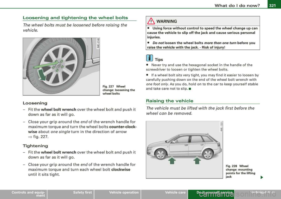
- Fit the wheel bolt wrench over the whee l bo lt and push it
down as far as it w ill go.
- C lose your grip around the
e n d of the wrench ha n dle for
maximum torque and t urn the wheel bolts counter-clock
wi se abo ut
one single turn in the direction of ar ro w
=> fig. 227.
Tight ening
Fit the wheel bolt wrench over the wheel bolt and push it
down as far as it w ill go .
- C lose your grip around the
end of the wrench handle for
maximum torque and turn each wheel bolt clockwise
until it sits tight.
LJ}. WARNING
• Using f orc e without control t o speed t he wh eel ch a nge up can
c au se th e vehicle t o slip off the jack and cau se seriou s per son al
injurie s.
• Do n ot lo osen the wheel b olt s more than one turn before y ou
r a is e th e vehi cle with the jack .
-Ris k of inju ry!
[ i] Tip s
• Never try and use the hexagonal socket in the handle of the
screwdriver to loosen or tighten the wheel bolts .
• If a whee l bolt sits very tight, you may find it easier to loosen by
carefully pushing down on the end of the whee l bolt wrench w ith
one foot only . As you do, ho ld on to the car to keep yourself stab le
and take care not to slip. •
Raising the vehicle
The vehicle must be lifted with the jack first before the
wheel can be removed.
F ig . 228 W hee l
c ha nge : m ount ing
po ints
for th e li fting
j ack _,.
Do-it-yourself service irechnical data
Page 324 of 368
-What do I do now? Pt'l:f....__ ______________ _
Fig. 229 Clo se- up:
pr ope r pos itio ning of
l ifting ja ck
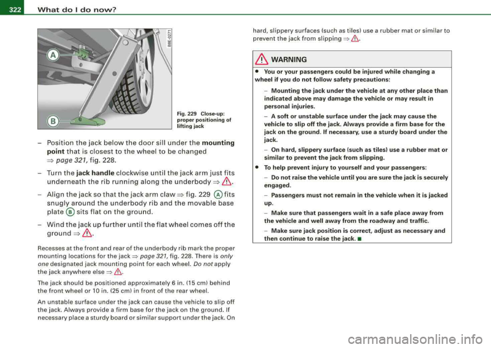
- Posi tion the jack below the doo r si ll un der the mounting
point
t h at is c losest to the whee l to be changed
=> page 321, fig . 228.
- Turn the
jack handle cloc kw ise unt il the jack arm jus t fits
underneath the rib running along th e under body
=> & .
Align the jack so that th e jack arm claw=> fig. 229 @ fits
snugly arou nd the under bod y rib and t he movab le base
plate @ sits flat on the ground.
W ind t he jac k up fur ther until th e fl at wh eel comes off th e
g roun d=> & .
Recesses a t the fron t a nd r ear of th e u nderbody rib ma rk the prop er
mounting locations for the
jack~ page 321 , fig. 228. There is only
one
designated jack mo unting point fo r each w hee l. Do not apply
the jack anywhere else
=> & -
The jack should be positioned approximately 6 in. (15 cm) behind
t he fron t whe el or 10 in . (25 cm) in fron t of t he rear whee l.
An unstab le surface unde r the jack can cause the vehicle to s lip off
the jac k. Alwa ys provi de a fir m base fo r the jack on the g roun d. If
necessary place a sturdy board or simi lar support under the jack . On hard
, slippery surfaces (su ch as tiles) use a rubber mat or simi lar to
p revent the jack fr om
slippi ng => & .
& WARNING
• You or your pa ssengers could be injured while changing a
wheel if you do not follow safety precaut ions:
- Mounting the jack under the veh icle at any other place than
indicated above may damage the vehicle or may result in
personal injuries .
- A soft or unstable surfa ce under the ja ck may cause the
vehicle to slip off the ja ck. Always provide a firm base for the
jack on the gro und .
If nece ss ary , use a sturdy board under the
jack .
- On hard , slippery surface (such as tiles) use a rubber mat or
similar to prevent the jack from slipping .
• To help prevent injury to yourself and your passengers :
- Do not raise the vehicle until you are sure the jack i s securely
engaged .
- Passengers must not remain in the vehicle when it is jacked
up .
- Make sure that pa ssengers wait in a s afe pla ce away from
the vehicle and well away from the roadway and traffic .
- Make sure jack position is correct , adjust as necessary and
then continue to raise the jack .
•
Page 325 of 368
What do I do now? -
------------------'
Taking the wheel off /putting the spare on
Follow these instructions step-by-step for changing the
wheel
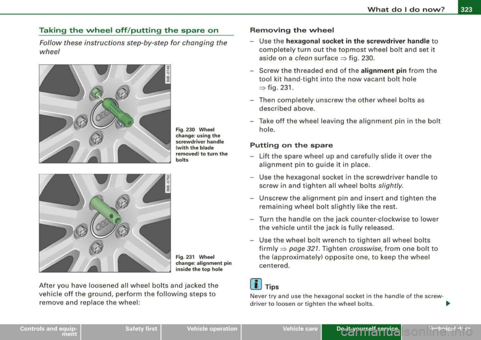
Fig . 230 Wheel
change : using the
screwdriver handle
(with the blade
removed) to turn the
bolts
Fig . 231 Wheel
change : alignment pin
inside the top hole
After you have loosened all wheel bolts and jacked the
vehicle off the ground, perform the following steps to
remove and replace the wheel:
Removing the wheel
-Use the hexagonal socket in the screwdriver handle to
completely turn out the topmost wheel bolt and set it
aside on a
clean surface => fig. 230.
-Screw the threaded end of the alignment pin from the
tool kit hand -tight into the now vacant bolt hole
=> fig. 231 .
-Then completely unscrew the other wheel bolts as
described above.
-Take off the wheel leaving the alignment pin in t he bolt
hole.
Putting on the spare
-Lift the spare wheel up and carefully slide it over the
alignment pin to guide it in place.
-Use the hexagonal socket in the screwdriver handle to
screw in and t ighten all wheel bolts
slightly .
-Unscrew the alignment pin and insert and tighten the
remaining wheel bo lt slightly like the rest.
-Turn the handle on the jack counter-clockwise to lower
the vehicle until the jack is fully released.
-Use the wheel bolt wrench to tighten all wheel bolts
firmly =>
page 327. Tighten crosswise, from one bolt to
the (approximately) opposite one, to keep the wheel
centered.
[ i] Tips
Never try and use the h exagonal socket in the handle of the screw -
driver to loosen or tighten the wheel bolts.
.,
Do-it-yourse lf service irechnical data
Page 326 of 368
____ w_ h_ a_t _ d_ o_ l_d _ o_ n_ o_w _ ? ______________________________________________ _
• Pull the reversible b lade from the screwdriver before you use the
h exago nal soc ket i n the ha ndle to tur n the wheel bo lts.
• When mounting tires with
unidirectional tread design make sure
th e trea d pat tern is po inte d the rig ht
way => page 324.
• T he whee l bo lts should be clean and easy to turn. Check for dirt
and c orrosio n on the m ating su rfaces of bo th the whee l a nd th e
hub . Remove a ll dirt from these surfaces before remou nting the
w heel. •
Tires with unidirectional tread design
T ir es wit h unid irectio nal tr ea d d esign must b e moun ted
with th eir tread pattern po int ed the r ight direction .
Using a spare tire with a tread pattern intended for use
in a specific direction
Whe n usi ng a s pa re t ire wi th a tre ad patte rn inte nd ed for use in a
specific direct ion, please note the followin g:
• The di rec tio n of rot ation is marked by an arr ow on th e s ide o f the
tir e.
• If the s pare tir e ha s to be ins talle d in th e inco rrect directi on i n the
event of a flat tire, use th e spar e tire on ly temporarily since the tire
w ill n ot be a ble to achieve it s optimum pe rform ance cha rac te ri sti cs
wi th r egar d to a qua plani ng , noise an d w ear .
• W e rec om mend th at p arti cula r att ent ion be pai d to this fac t
dur in g wet weath er and that you adjust your sp eed to match road
c o nd it io ns.
• R eplace the flat ti re with a new one and have it instal led on your
v e hi cle as soo n as poss ib le to re st ore th e hand ling a dva ntages of a
p roper ly pointed direction -dependent t ire.•
Notes on wheel change
P lease read the information => page 305 , "N ew tire s and replacing
t ir es a nd whe els" if you are going to use a spa re tire w hich is
different from the t ires on you r ve h ic le.
Aft er you ch ange a tire:
• Check the tire pressure on the spare immediately after
mounting .
• Have the wheel bolt tightening torque checked with a torque
wrench as soon as possible by your authorized Audi dealer or a qualified service station .
• On steel and alloy wheel rims , the wheel bolts are correctly tight
ened with a torque of 90 ft lb (120 Nm ).
• If you notice while changing a tire that the wheel bolts are
corroded and difficult to turn while changing a tire , they should be
replaced before you check the tightening torque.
• Replace the flat tire with a new one and have it installed on your
vehicle as soon as possible . Remount the wheel cover.
Until then, drive with extra care and at reduced speeds .
& WARNING
• If you are going to equip your vehi cle with tires or rims which
differ from those which were factory installed , then be sure to read
the information
=> page 305 , "New tires and replacing tires and
wheels ".
• Always make sure the damaged wheel or even a flat tire and
the jack and tool kit are properly secured in the luggage compart
ment and are not loose in the passenger compartment .
• In an accident or sudden maneuver they could fly forward ,
injuring anyone in the vehicle .
• Always store damaged wheel, jack and tools securely in
luggage compartment . Otherwise, in an accident or sudden
Page 327 of 368

What do I do now? -
----------------
& WARNING (continued )
maneuver the y could fl y forward , causing injury to passengers in
the vehicle.
0 Note
Do no t use com merc ial ly availab le tire seala nts. O the rw ise, t he elec
trica l components of the tire pressure monitoring system * wil l no
l o nger work p roperly and t he sensor fo r the tir e pressure moni
toring system wi ll have to be replaced by a qua lified workshop .•
Do -it -yourself service
Page 328 of 368

1119....__F_ u_ s_ e_s _ a_n _ d_ b_ u_lb _ s _______________________________________________ _
Fuses and bulbs
Fuses
Repl ac ing a fu se
A problem in the electrical system may be caused by a
blown fuse.
Fig . 232 End face of
instrument panel :
removing cover plate
to access fuses
Fig . 233 Fuse carrier
behind the instrument
panel end face, cover
removed
- Switch off the ignition and the electrical component
affected.
- Carefully pry the face cover off the instrument panel
using the ignition key or a
screwdriver ~ fig. 232.
- Check the fuse listing on the next pages to find out which
fuse belongs to the component which has failed
~ page 327, "Fuse list".
- Remove the blown fuse with the plastic clip provided.
The clip is located on the holder in the fuse box.
- Replace a blown fuse (recognizable by the melted metal
strip inside) with a fuse of the same amperage .
- Firmly snap the cover back onto the instrument panel
face.
The various electrical circuits are protected by fuses. The fuses are
clustered in a centralized unit. The unit is located behind the face
panel at the end of the instrument panel. The crank for operating
the sunroof in case of a power failure is also stored behind the face
panel ~ page 70.
Two spare fuses and a sticker identifying the fuses are located on
the inside of the fuse box cover.
You are well advised to keep a supply of spare fuses in your vehicle.
Fuses with the proper ampere ratings are available at your Audi
d ea le r.
& WARNING
Never replace a fuse with one that has a higher amperage rating.
• A fuse with a too high amperage could damage the electrical
part and cause a fire.
~
Page 329 of 368

Fuses and bulbs -
----------------
0 Note No. Equipment Amps
• On no account should fuses be repaired (e.g. patched up with tin 13 Steering column module 10
foil or wire) as this may cause serious damage elsewhere in the elec -14 Brake lights 10
trical circuit or cause fire.
15 Instrument cluster, Navigation system 10
• If a fuse blows repeatedly, do not keep replacing it. Instead, have
the cause for the repeated short circuit or overload tracked and Garage door opener
5
fixed.
•
Level, tire pressure control, park assist,
17 light/rain sensor 10
Fuse list Automatic headlight range control, left 5
Fuses which can be replaced. 19 Fog lights, rear fog light 15
20
Not used
No. Equipment Amps
21 Not used
1 Air conditioner 10 Front doors 15
2
Footwell illumination 5 23 Rear doors 15
3 Heated washer jets 5 Central convenience electrical system 20
4 Radiator fan 5 25 Heater blower 30
5
Telephone, oil level sensor, multifunction 10 26 Rear window defogger 30
switch, rear heated Seat, shift gate
27 Socket for trailer towing (controller) 30
6
Air conditioner (air quality sensor), air pressure 5 28 Fuel pump 20 sensor
Electronic Stabilization Program (ESP), brake
29 Not used
7 light switch, clutch pedal switch, steering angle 10 Power sunroof 20
sensor Automatic transmission, mirror dimming, diag-
31 15 8 Telephone 5 nosis socket
9 Brake booster (vacuum pump) 15 Towing assembly 15
10
Automatic headlight beam adjustment, auto -5 33 Cigarette
lighter 20
matic headlight range control, right
Electrical socket 20
11
Airbag 5 35 Luggage compartment socket 20
12
Diagnosis socket 10 Windshield wiper system 30
Do -it -yourself service
Page 330 of 368
11111.___F_ u_ s_ e_s _ a_ n_d _ b_u_ l_ b _ s ______________________________________________ _
No.
37
38
39
40
41
43
44
Equipm ent
Pump for windshie ld and headlight washer *
system
Central elect ric, anti -theft a larm system, rear
lid/ tr u nk release
Rad io
Horn
Auxiliary hea tin g
Electronic Stab ilization P rogram (ESP)
Engine timing
Seat heating
Automatic circuit bre akers : Amps
30
15
20
25
30
25
15
35
T he electric power windows and the electr ic seat adjusters are
pro tected with circu it breakers which reset automatica lly after the
circuit overload has been corrected .
[ i ] Tip s
• Whenever replacing a fuse, always consult the sticker on the
inside of the fuse panel cover . It contains the most up -to -date info r
mat ion regarding the fuse arrangement . If in doubt , ask your autho
rized Audi Service adv isor .
• Some of the equipment items listed are op tiona l o r only avail
able on certa in model configu rations .•
Bulbs
A pplies to vehicle s: wit h xenon he ad ligh ts
Replacing light bulbs
For your safety, we recommend that you have your autho
rized Audi dealer replace any bulbs for you.
I t is becoming increasing ly more and more difficult t o replace
vehic le light bulbs since in many cases, other parts of the car must
first be removed before yo u are able to get to the bu lb . T his applies
especia lly to the ligh t bu lbs in the front of your car which you can
only reach th rough the eng ine compartment.
Sheet metal and bulb ho lders can have sharp edges that can cause
s e rious cuts, and parts must be correctly taken apart and th en prop
erly put back together to help prevent breakage of par ts and long
te rm damage from water that can enter housings that have not
been properly resealed .
For your safety , we recommend that you have your authorized Audi
dea ler replace any bulbs for you, since your dealer has the prope r
tools, the correct bulbs and the expertise .
Gas di sc harge l amp s (x enon l ight s)*:
Due to the h igh e lectrical voltage, have t he bu lbs replaced by a qual
ified technician . Head lights with xenon light are identified by the
high voltage sticker .
& WARNING
Changing xenon lamps without the ne cessary equipment c an
c au se seriou s per sonal injury .
• Bulb s are pres surized and can explode when being changed.
Potential ri sk of injur y!
• On vehicle s equipped with ga s di scharge bulb s (xenon ligh t)*
life -threaten ing injurie s can re sult from impr oper h andling of the
high -voltage portion s of su ch lamp s!
~