radio AUDI A5 COUPE 2010 Owners Manual
[x] Cancel search | Manufacturer: AUDI, Model Year: 2010, Model line: A5 COUPE, Model: AUDI A5 COUPE 2010Pages: 360, PDF Size: 84.39 MB
Page 9 of 360
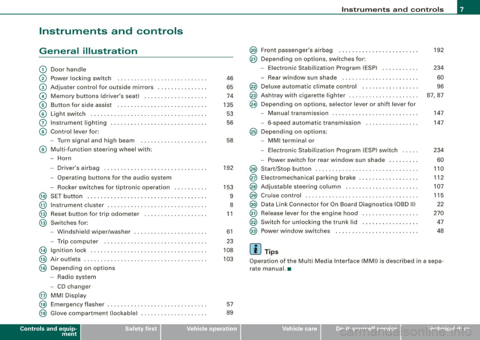
Instruments and controls
General illustration
G)
0
©
©
©
©
0
©
Door handle
Power locking switch
Adjuster contro l for outside mi rrors .. ...... ...... .
Memory buttons (driver's seat) .. ....... ...... ... .
Button for side assist ..... .... ... .. ...... ... ... .
Light switch .. ...... ....... ... ... .. .... ....... .
Instrument lighting ...... ..... .. .... .... ...... . .
Control lever for :
- Turn signal and high b eam
® Multi -function steering wheel with:
- Horn
-Driver's airbag .... ..... .. .... .... .... .... ... .
- Operating buttons for the audio system
- Rocker swi tches for tiptronic operation ...... ... .
@ SET button ..................... .... .......... .
@ Instrument cluster . ...... ........ .............. .
@ Reset button for trip odometer ... ...... ...... ... .
@ Swi tches for:
@
@
@
@
@
@
- Windshield wip er/washer ............. ... .. ... .
- Trip computer ..... .. .... .... ...... .... ... .. .
Ign ition lock .... .... .... ...... .... ... ... ... ... .
Air ou tlets ........... .... ..... ........... ... .. .
Depend ing on options
- Radio system
- CD changer
MM I Display
Emergency flasher
G love compartment ( lockab le)
Controls and equip
ment
46
65
74
135 53
56
58
192
153
9
8
11
61
23
108
103
57
89
Instruments and controls
@ Front passenger's airbag ......... ... .... .... ... .
@ Depending on options, switches for:
@
@
@
@
@
@
@
@
@
@
@
@
- Elect ron ic Stabilization Program (ESP) ..... .. .. . .
- Rear window sun shade ..... ... ... ... ... .. ... .
Deluxe automatic climate control . .... .... .... ... .
Ashtray with cigare tte lighter ..... ...... .. .... ... .
Depending on options, selector lever or shift l ever for
- Manual transmission ........ .... ....... .. . ... .
- 6-speed automatic transmission
Depending on options:
- MMI terminal or
- Electronic Stabil ization Program (ESP) switch
- Power switch for rear window sun shade ........ .
Start/Stop button .... .... ... .... .... .... .... ... .
Elect romechanical parking brake ... .... .... ...... .
Adjus tab le ste ering column .. ...... ...... ..... .. .
Cruise control .... ... .... .... .... .... .... ... ... .
Data Link Connector for On Board Diagnostics (OBD Ill
Release lever for the engine hood ........ ........ .
Switch for unlocking the trunk lid ...... .... .. .. .. .
Power window switches
[ i ] Tips
192
234
60
96
87,87
147
147
234
60
110
112
107
115
22
270 47
48
Operation of the Mu lti Media Interface (MMll is described in a sepa
rate manual. •
I • •
Page 12 of 360
![AUDI A5 COUPE 2010 Owners Manual Instruments and warning/indicator lights
Switching on time, date, temperature display, and
odometer
The display appears for approximately 30 seconds when you press
the !SET] but AUDI A5 COUPE 2010 Owners Manual Instruments and warning/indicator lights
Switching on time, date, temperature display, and
odometer
The display appears for approximately 30 seconds when you press
the !SET] but](/img/6/57582/w960_57582-11.png)
Instruments and warning/indicator lights
Switching on time, date, temperature display, and
odometer
The display appears for approximately 30 seconds when you press
the !SET] button =>
page 9, fig. 3 with the ignition off.
Starting the Auto-Check sequence
The Auto -Check system => page 27 constantly monitors certain indi
vidual functions and components of the vehicle when the ignition is
turned on and when the vehicle is moving.
With the ignition turned on, you can start the "Auto-Check
sequence" by pressing the !SET ] button . You can perform an Auto
Check sequence when the vehicle is stationary and the ignition is
turned on or when the vehicle is moving slower than 3 mph (5 km/hl.
Calling up the driver information
A yellow or red symbol appears in the instrument cluster display,
usually with a driver message. The driver message display disap
pears after about 5 seconds. The driver message can be displayed
again by briefly pressing the !SET] button.
Setting the speed warning
By pressing the [SET] button briefly, you can set threshold 1 of the
speed warning while you are driving=>
page 26. By maintaining
pressure on the !SET] button, you delete the warning threshold. •
Digital clock with date display
Digital clock
Fig. 4 Instrument
cluster: time and date
The date, time of day, time and date format can be set in the radio
or MMI*. You can learn more about this in the MMI manual or in the
radio user's manual.
[ i] Tips
• The digital clock turns on for about 30 seconds when the driver's
door is opened.
• When the ignition is turned off, the odometer reading and the
digital clock with date display can be switched on for about
30 seconds by pressing the !SET] button =>
page 9, fig. 3. •
Fuel gauge
The fuel gauge works only when the ignition is on.
When the needle reaches the red area, the warning light in the
instrument cluster will illuminate=>
page 35 . This means you
have approximately 2.1 gallons (8 liters) of fuel left in the tank.
Time
to refuel!
The total tank capacity of your vehicle is listed in=> page 337. .,,
Page 13 of 360
0 Note
Never run the tank completely dry! An irregular supply of fuel can
cause engine misfiring and fuel could enter into the exhaust
system. The cata lytic converter could then overheat and be
damaged .•
Odometer
The odometer indicates the distance driven.
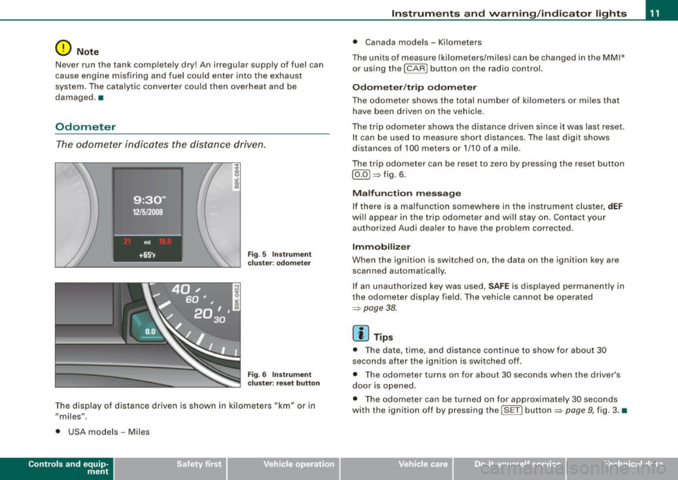
Fig. 5 Instrument
cluster: odometer
Fig . 6 Instrument
c luste r: reset button
The display of distance driven is shown in kilometers "km" or in
"miles".
• USA models -Miles
Con tro ls and eq uip
ment
Instruments and warning /indicator lights
• Canada models - Kilometers
The units of measure (kilometers/miles) can be changed in the MMI*
or using the
I CAR I button on the radio control.
Odometer/trip odometer
The odometer shows the total number of kilometers or miles that
have been driven on the vehicle .
The trip odometer shows the distance driven since it was last reset.
It can be used to measure short distances. The last digit shows
distances of 100 meters or 1/10 of a mile.
The trip odometer can be reset to zero by pressing the reset button
[ 0.0] => fig. 6.
Malfunction message
If there is a malfunction somewhere in the instrument cluster,
dEF
will appear in the trip odometer and will stay on . Contact your
authorized Audi dealer to have the problem corrected.
Immobilize r
When the ignition is switched on, the data on the ignition key are
scanned automatically .
If an unauthorized key was used,
SAFE is displayed permanently in
the odometer disp lay field. The vehicle cannot be operated
=> page 38.
[ i ] Tips
• The date, time, and distance cont inue to show for about 30
seconds after the ignition is switched off.
• The odometer turns on for about 30 seconds when the driver's
door is opened .
• The odometer can be turned on for approximate ly 30 seconds
with the ignition off by pressing the [SET ] button=> page 9, fig. 3. •
Vehicle care
I I irechnical data
Page 20 of 360
Driver informati on displ ay
Driver information display
Introduction
General notes
The driver information display inside the instrument
cluster provides you, the driver, with much useful infor
mation.
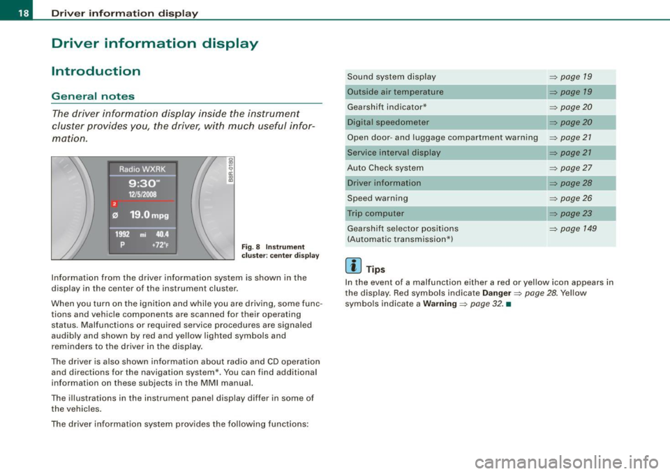
Fig . 8 Inst rum ent
c lu ster : cente r dis pl ay
Informat ion from the driver information system is shown in the
display in the center of the instrument cluster.
When you turn on the ignition and while you are driving, some func
tions and vehicle components are scanned for their operating status. Malfunctions or required service procedures are signaled
audibly and shown by red and yellow lighted symbols and
reminders to the driver in the display.
The driver is also shown information about radio and CD operation and directions for the navigation system *. You can find additional
information on these subjects in the MMI manual.
The illustrations in the instrument panel display differ in some of
the vehicles.
The driver informat ion system prov ides the following functions: Sound sys
tem display ::::;,
page 19
Outside air temperature ::::;, page 19
Gearshift indicator* _________ ::::;, page 20
Digital speedometer ::::;, page 20
Open door- and luggage compartment warning ::::;, page 21
Service interval display
Au to Check syst em
Driver information
Speed warning
Trip computer Gearshift selector positions
(Automatic transmission*)
[ i ] Tips
::::;, page 21
::::;, page27
::::;, page28
::::;, page26
::::;, page23
::::;, page 149
In the event of a malfunction either a red or yellow icon appears in
the display. Red symbols indicate
D anger ~ page 28. Yellow
symbols ind icate a
Warning ::::;, page 32. •
Page 21 of 360
Sound system display
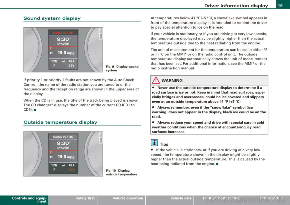
Fig. 9 Di spla y: s ound
system
I f priority 1 or priority 2 faults are not shown by th e Auto Check
Co ntro l, the name of the ra dio s ta tion yo u are tune d to or the
frequency and the reception range are shown in the upper area of
t he d isplay .
Whe n th e CD is i n use , the title of t he track bei ng p layed is shown .
T he CD changer * displays th e number of the current CD (CD 1 to
CD6l . •
Outside temperature display
Con tro ls and eq uip
ment
Fig . 10 Disp lay:
out side temper atu re
Driver information display
At temperatures be low 41 °F (+5 °C), a snowflake symbol appears in
fr ont of t he te mp eratur e dis play . It is inte nded to remind the d river
to pay special attent ion to
ice on the road.
If your vehicle is stationa ry or if you are d riving at very low speeds,
th e te mpera ture d isplaye d may b e slig htly h igher t han the actu al
temperature outside due to the heat radiating from the engine.
The unit o f measu rement for the temp erature ca n be set in eit her °F
or in °Con the MM I* or on the radio control unit . The outside
tempe rature display a utoma tical ly sh ows the unit of meas urement
that has been set. For additional information , see the MM I* or the
r adi o ins tructi on manual.
& WARNING
• Never use the outside temperature display to determine if a
road surfa ce is icy or not . Keep in mind that road surfa ces , espe
cially bridges and overpasses, could be ice covered and slippery
even at an outside temperature above 41
° F (+5 °C ).
• Always remember, even if the "snowflake " symbol (ice
wa rning) does not appear in the display , black ice could be on the
road .
• Always reduce your speed and drive with special care in cold
weather conditions when the chance of encountering icy road surfaces in creases .
[ i ] Tip s
• I f the vehic le is stationary , or if you are driving at a very low
speed, the temperature shown in the d isplay migh t be slightly
h ig her than the actual outside temperature. This is caused by the
heat being radia ted from the engine .•
Vehicle care I I irechnical data
Page 22 of 360
Driver information display
Applies to vehicles: with m anu al tr ansmi ssion and g earsh if t indica tor
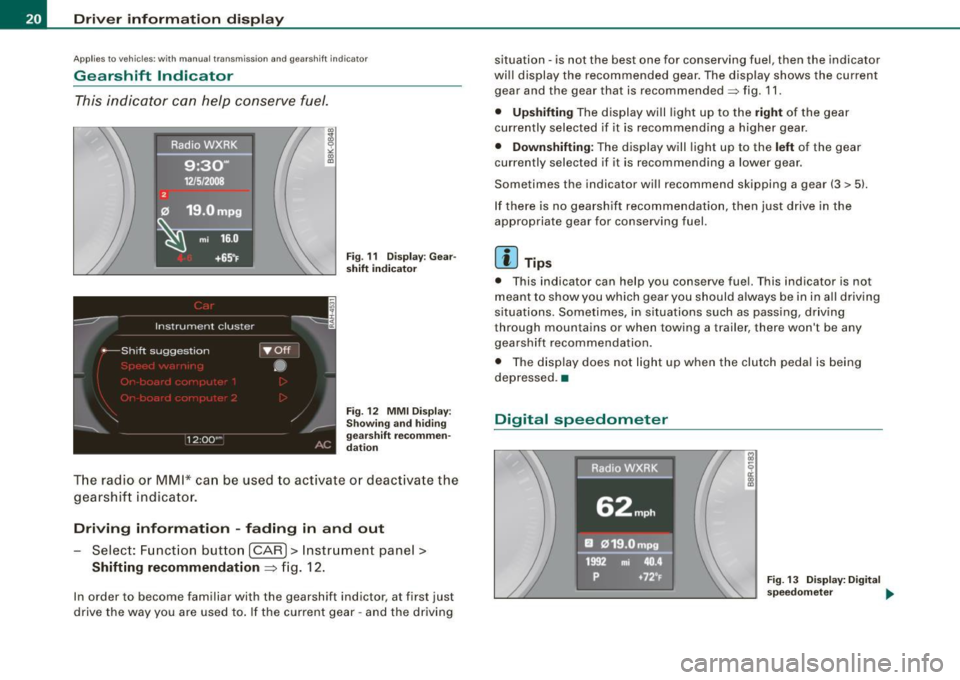
Gearshift Indicator
This indicator can help conserve fuel.
mi 16.0
+6 5°F Fig . 11 Display : Gear
shift indicator
Fig . 12 MMI Display:
Showing and hiding
gearshift recommen
dation
T he radio or MMI* can be used to activate or deactivate the
gearshift indicator.
Driving information -fading in and out
Select: Function button [CAR]> Instrument panel>
Shifting recommendation => fig. 12.
In order to become familiar with the gearshift indictor, at first just
drive the way you are used to . If the current gear -and the driving situation
-is not the best one for conserving fuel, then the indicator
will display the recommended gear . The display shows the current
gear and the gear that is recommended~ fig. 11.
• Upshifting The display will light up to the right of the gear
currently selected if it is recommending a higher gear.
• Downshifting: The display will light up to the left of the gear
currently selected if it is recommending a lower gear .
Sometimes the indicator will recommend skipping a gear (3
> 51.
If there is no gearshift recommendation, then just drive in the
appropriate gear for conserving fuel.
[ i ] Tips
• This indicator can help you conserve fuel. This indicator is not
meant to show you which gear you should always be in in all driving
situations. Sometimes , in situations such as passing , driving
through mountains or when towing a trailer, there won't be any
gearshift recommendation.
• The disp lay does not light up when the clutch peda l is being
depressed .•
Digital speedometer
Fig. 13 Display: D igital
speedometer ...
Page 24 of 360
Driver information display
Service due
When the due date for service is reached, the message Service due
! appears in the instrument cluster immediately after you turn on
the ignition. Additionally, a warning tone sounds. After about 5
seconds the display switches back to normal.
Calling up the service schedules
If or when an oil change or inspection is due , can be shown in the
radio or MMI* display by selecting the service interval display in the
car menu. Select
[CAR]> Service interval display=> page 21, fig. 15.
Resetting the service interval display
Your authorized Audi dealer will reset the corresponding service
schedule after performing the appropriate service on your vehicle.
You also have the possibility to reset the oil change schedule after
having performed an oil change according to Audi specifications .
Select
(CAR]> Service interval display> Re set oil change interval.
0 Note
If you disconnect the battery terminals, no calculations can be
made for the service interva l display during this time and no service
reminder will appear. Remember that observing the proper service
interva ls is vita lly important to extending the life of your vehicle,
particularly the engine, and maintaining its value. Even if the
mileage driven is low, the maximum period of one year from one
service to the next must not be exceeded.
[ i ) Tips
• Do not reset the display between oil changes, o therwise the
display will be incorrect .
• The information in the Service Reminder remains stored
even
when the vehicle battery is disconnected. •
On-Board Diagnostic system (08D)
Malfunction Indicator Lamp (MIL)
The Malfunction Indicator Lamp (MIU in the instrument cluster
=> page 12, fig. 7 is part of the On-Board Diagnostic (OBD II) system.
The warning/ind icator light illuminates when the ignition is
switched on and goes out after the engine starts and the id le has
stabi lized. This indicates that the MIL is working proper ly .
If the light does not go out after the engine is started, or illuminates
while you are driving, a ma lfunction may exist in the engine system.
If the light illuminates, the catalytic converter could be damaged.
Continue driving
with reduced power (avoiding sustained high
speeds and/or rapid accelerations) and have the condition
corrected. Contact your authorized Audi dealer.
If the light illuminates, the electronic speed limiter may also be
malfunctioning. For more information=>
page 23, "Electronic speed
limiter".
An improperly closed fuel filler cap may also cause the MIL light to
illuminate
=> page 267. •
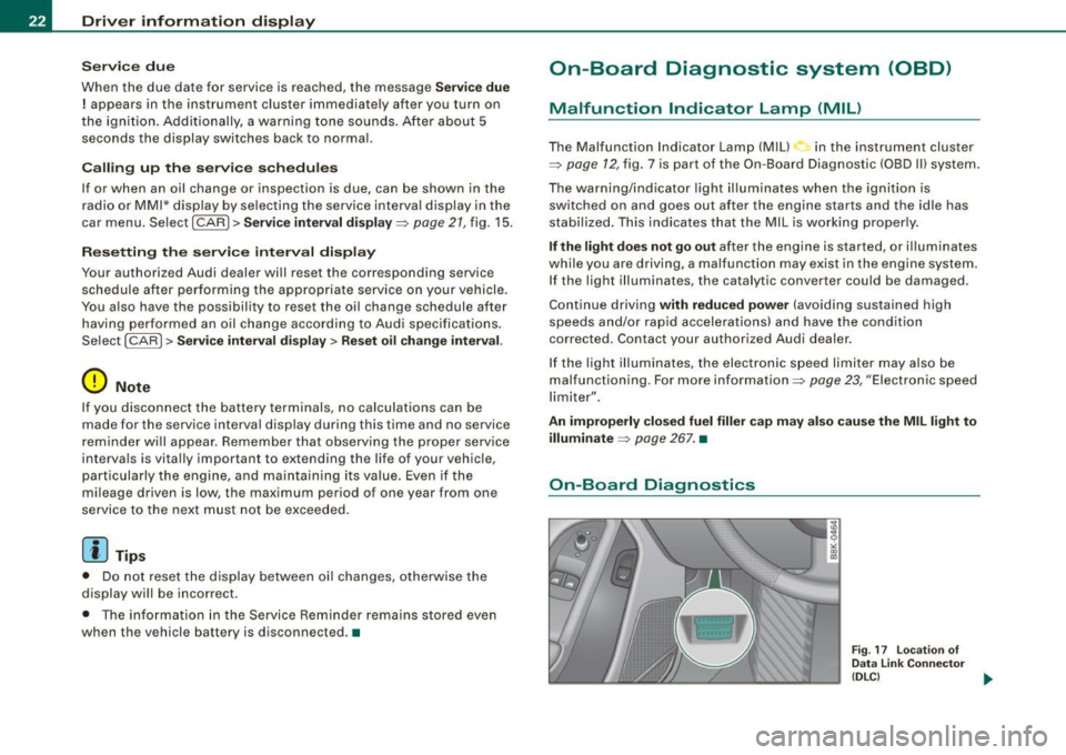
On-Board Diagnostics
Fig. 17 location of
Data Link Connector
(DLC)
ai,,,
Page 27 of 360
tion. If the trip is interrupted for more than 2 hours the memory is
reset automatica lly.
Total-trip memory (Trip computer 2)
Unlike the single-trip memory, the total-tr ip memory is not reset
automatically. This permits you to evaluate your driving data for the
entire period between manual resets. •
Operation
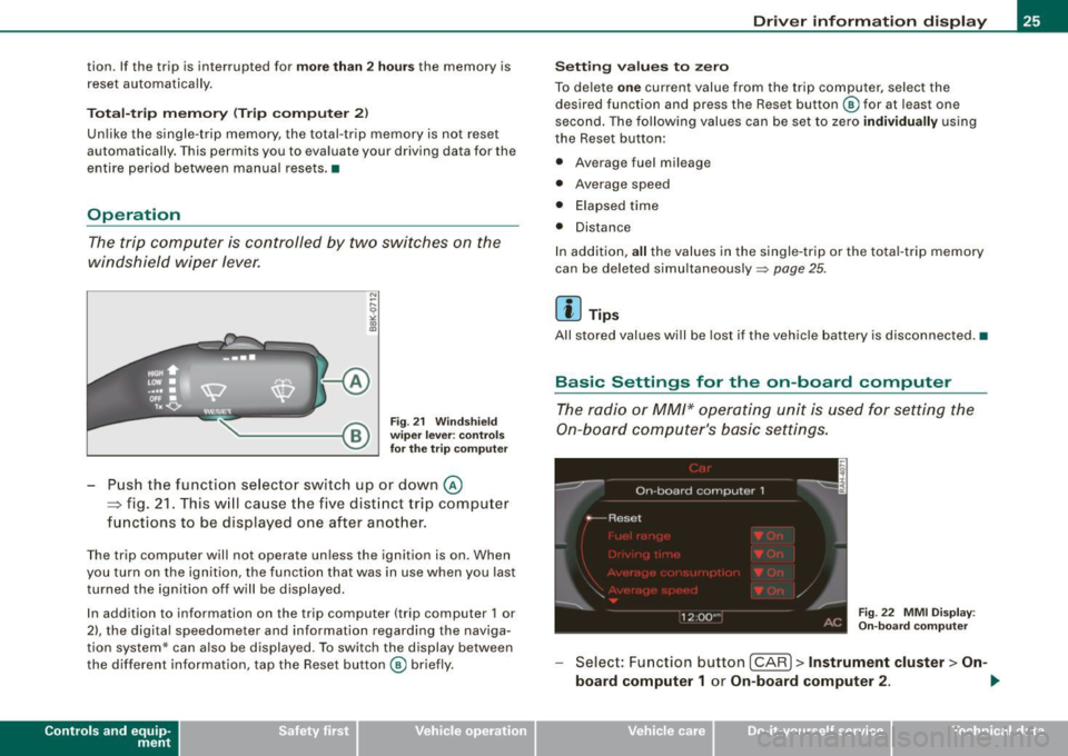
The trip computer is controlled by two switches on the
windshield wiper lever.
Fig. 21 Windshield
wiper lever: controls
for the trip computer
Push the function selector switch up or down@
~ fig. 21. This will cause the five distinct trip computer
functions to be displayed one after another.
The trip computer will not operate unless the ignition is on. When
you turn on the ignition, the function that was in use when you last
turned the ignition off will be displayed.
In addition to information on the trip computer (trip computer 1 or
2), the digital speedometer and information regarding the naviga
tion system* can also be displayed. To switch the display between
the different information, tap the Reset button@ briefly.
Con tro ls and eq uip
ment
Driver information display
Setting values to zero
To delete one current value from the trip computer, select the
desired function and press the Reset button @ for at least one
second . The following values can be set to zero
individually using
the Reset button:
• Average fuel mileage
• Average speed
• Elapsed time
• Distance
In addition,
all the values in the single-trip or the tota l-trip memory
can be deleted simultaneously::::,
page 25.
[ i ] Tips
All stored values will be lost if the vehicle battery is disconnected. •
Basic Settings for the on-board computer
The radio or MM/* operating unit is used for setting the
On-board computer's basic settings.
Fig. 22 MMI Display :
On-board computer
Select: Function button [CAR]> Instrument cluster > On -
board computer 1
or On-board computer 2 . 1iJ,,
Vehicle care I I irechnical data
Page 29 of 360
Storing th e maximum sp ee d
- Drive at the desired max imum speed.
- Press the
(SET) button in the instrument pane l d isp lay
~ page 26, fig. 23 for 1 second.
R ese ttin g th e m ax imum sp eed
- Drive the vehicle a t a speed of at least 3 mph (5 km/h)
- Press the
(SETI button for more than 2 seconds.
The speed warning symbol 8 (USA modelsl/ e) (Canada mode ls) will
appear briefly in the display when you release the
[SE T) button to
indicate that the maximum speed has been stored successfully.
The maximum speed remains stored until it is changed by pressing
the
I S ET) button again briefly or unt il it is deleted by a lengthy push
on the button. •
Speed warning 2: setting a speed limit
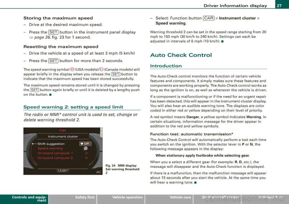
The radio or MM/* control unit is used to set, change or
delete warning threshold 2.
Controls and equip
ment
Fig . 24 M MI d is pl ay :
Set warnin g thresho ld
2
Dr ive r informat ion di spl ay
- Select : Function button [ CAR l > In strument clu ster >
Spe ed warning.
Warning thresho ld 2 can be set in the speed range starting from 20
mph to 150 mph (30 km/h to 240 km/h). Settings can each be
adjusted in in tervals of 6 mph (10 km/h). •
Auto Check Control
Introduction
The Auto-Check control monitors the function of certain vehicle
features and components . It simply makes sure these features and
components are working properly. The Auto -Check contro l works as
long as the ignition is on, as well as whenever the vehic le is driven.
If a component is malfunctioning or if the need for an urgent repair
has been detected, this will appear in the instrument cluster d isplay .
You will also hear an audible warning tone . The displays are color
coded in either red or yellow depending on their level of priority.
A red symbo l means
D ang er, a yellow symbol ind icates W arning . In
certain situations, information message for the driver appear in
addition to the red and yel low symbo ls.
Fun ctio n t est: a uto matic t ransm iss ion *
The Auto -Check Control will automatical ly perform a test each time
you switch on the ignition . With the selector lever in
P or N , the
fo llowing message appears in the display :
When statio nar y a ppl y fo otb rake whil e se lecting g ear.
When you a se lect a different gear (for example: R , D , etc.), the
message will disappear and the Auto-Check function is displayed.
If there is a ma lfunction, th en th e malfunction message will appear
about 15 seconds after you start the vehic le. At the same t ime you
wi ll hear a warning tone. •
I • •
Page 41 of 360

[ i J Tips
• The operation of the remote control key can be temporarily
disrupted by interference from transmitters in the vicinity of the
vehicle working in the same frequency range {e .g . a cell phone,
radio equipment).
• If you open the driver's door with the key left in the ignition lock,
a chime will sound. This is your reminder to remove the key and lock
the door.
• For security reasons, replacement keys are only available from
Audi dealers.
• For Declaration of Compliance to United States FCC and Industry
Canada regulations~
page 342. •
Check light in the master key
The check light in the master key provides information
about different conditions.
!
lJl
Fig. 29 Check light in
the master key
The check light comes on briefly once when a button is pressed, and
during an "inquiry" by the convenience key system.
Con tro ls and eq uip
ment
Opening and closing
If the check light does not come on, the battery is dead and has to
be replaced. In addition, when the battery is dead the symbol
appears in the instrument cluster display as well as the message :
Please change key battery
Battery replacement ~ page 39. •
Master key battery replacement
..
Fig. 30 Remote master
key: Removing the
mechanical key
Fig . 31 Remote master
key: Removing the
battery holder
We recommend having the battery changed by an autho
rized Audi dealer. However, if you wish to replace the dead
battery yourself, proceed as follows:
- Press the release button @=>fig. 30.
Vehicle care I I Technical data