Check AUDI Q7 2013 Owner´s Manual
[x] Cancel search | Manufacturer: AUDI, Model Year: 2013, Model line: Q7, Model: AUDI Q7 2013Pages: 348, PDF Size: 87.72 MB
Page 300 of 348
298 Tires and wheels
month and alway s before a long trip
~ page 286, Checking tire pressure.
What you can do to avoid tire and rim
damage
L ow aspect ratio tires can be damaged more
eas ily by impact with potho les, curbs, gu llies
or ridges on the road, particularly if the tire is
underinflated.
I n order to minimize the occu rrence o f impact
damage to the tires of your vehicle, we recom
mend that you observe the following precau
tions:
- Always maintain recommended inflation pressures. Check your tire pressure every
2,000 miles (3,000 km) and add a ir if neces
sary.
- Drive carefu lly on roads with potholes, deep
gullies or ridges. The impact from driving
through or over such obstacles can damage
your tires. Impact with a curb may also
cause damage to your tires.
- After any impact, immediately inspect your
tir es or have them inspected by the nearest
authorized Aud i dealer . Replace a damaged
t ir e as soon as possible .
- Inspect your t ires every 2,000 miles (3,000
km) for damage and wear . Damage is not al
ways easy to see. Damage can lead to loss of
air and unde rinflation, wh ich could eventu
ally cause tire failure. If yo u be lieve that a
tire may have been damaged, replace the
tire as soon as possible.
- T hese tires may wear more quickly than oth
ers.
- Please also remember that, while these tir es
deliver responsive handling, they may ride
l ess comfortably and make more noise than
other choices.
Reduced performance in winter/cold
season conditions
All tires are designed for certain purposes .
The low aspect ratio, ultra high performance
tires originally installed on your vehicle are in
tended for maximum dry and wet road per
formance and handling . They are not suitable
for cold, snowy or icy weather conditions . If you drive
under those circumstances, you
shou ld equip your vehicle with all-season or
winter tires , which offer better traction under
those conditions. We suggest you use the rec ommended snow or all-season t ires specified
for your vehicle, or their equivalent .
Refer to
~ page 295 for more detailed infor
mation regarding winter tires.
Tire pressure
monitoring system
ill General notes
Each tire, including the spare (if provided),
should be checked monthly when co ld and in
flated to the inflation pressure recommended
by the vehicle manufacturer on the vehicle
placard or tire inflation pressure label. (If your
vehicle has tires of a different size than the
s iz e indicated on the vehicle placard or tire in
flation pressure label, you should determ ine
the proper tire inflation pressure for those
tires).
As an added safety feature, your ve hicle has
been equipped with a tire pressure monitoring
system ( TPMS) that illuminates a low tire
pressure telltale when one or more of your
tires is significantly under-inflated. According
l y, when the low tire pressure te lltale illumi
nates, you should stop and check your tires as
soon as possible, and inflate them to the proper pressure . Driving on a sign ificantly un
der- inflated t ire causes the tire to overheat
and can lead to tire fa ilure. Under-inflation al
so reduces fuel efficiency and tire tread life,
and may affect the vehicle's hand ling and
stopping ability .
Please note that the TPMS is not a substitute
for proper tire ma intenance, and it is the driv
er's responsibility to maintain correct tire
pressure, even if under-inflation has not
reached the leve l to trigger illuminat ion of the
T PMS low tire pressure tellta le .
Your vehicle has also been equipped with a
T PMS ma lfunction indicator to indicate when
the system is not operating properly. The
ll>
Page 301 of 348
TPMS malfunction indicator is combined with
the low tire pressure tellta le . When the sys
tem detects a malf unct ion, the te lltale will
flash for approximately one minute and then remain cont inuously illuminated. This se
quence will continue upon subsequent vehicle
start-ups as long as the malfunction ex ists .
When the malfunct ion indicator is illuminat
ed, the system may not be able to detect or
sig nal low t ire pressure as intended . TPMS
malfunct ions may occur for a variety of rea
sons, including the installat ion of rep lace
ment or alternate tires o r whee ls on the veh i
cle that prevent the TPMS from funct io ni ng
p roperly. Always check the TPM S malfunct ion
tellta le after replacing one or more tires or
wheels on your vehicle to ensure that the re p lacement or a lternate tires and wheels allow
the TPMS to continue to function properly.
Tire pressure indicator appears
The tire pressure indicator in the instrument
cluster informs you if the tire pressure is too
low or if there is a system malfunction.
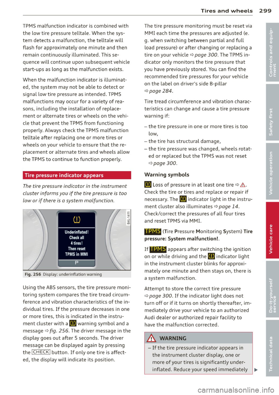
Fi g. 25 6 Display: under inflat io n warn ing
Using the ABS sensors, the tire pressure mon i
tori ng system compa res the t ire tread ci rcum
fe rence and vibration characteristics of the in
dividual tires. If the pressure decreases in one
or more tires, this is indicated in the instr u
ment cluster with a
IE warning symbol and a
message
c:> fig . 256. The driver message in the
d isplay goes out after 5 seconds. The driver
message can be d isplayed again by pressing
the
! CHECK I button . If only one tire is affect
ed, the display will indicate its pos ition .
Tire s an d wheel s 2 99
The t ire pressure monitoring must be reset via
MMI each time the pressures are adjusted (e.
g. when switching between part ia l and full
l oad pressure) or after changing or replacing a
tire on your vehicle
c:> page 300. The TPMS in
dicator on ly monitors the tire pressure that
you have prev iously stored . You can find the
recommended t ire pressures for you r vehicle
o n the label on driver's s ide 8-pillar
¢ page 284.
Tire tread circumference and vibration charac
teristics can change and cause a tire pressure
warning if:
- the t ire pressure in one or more tires is too
low,
- the t ire has structural damage,
- the t ire press ure was changed, wheels rotat-
ed or replaced but the TPMS was not reset
¢page 300.
Warni ng symbo ls
IE Loss of pressure in at least one tire ¢ &..
Check the tire or tires and rep lace or repa ir if
necessary. The
Rt] i ndicator light in the instru
ment cluster also illuminates¢
page 14.
Check/correct the p ressures of all four tires
and reset TPMS via MMI.
••NIB (T ire Pressure Monitoring System) Tir e
pressure: System malfunct ion!.
If llilW appears
after switching the ignition
on or while driving and the
IE indicator light
in the instrument cluster blinks for approxi
mately one minute and then stays on, there is
a system malfunct ion.
Attempt to store the correct tire pressure
¢
page 300. If the indicator light does not
turn off or if it turns on shortly thereafter, im med iate ly dr ive your vehicle to an author ized
Audi dealer or authorized repair fac ility to
have the malfunct ion corrected.
_&, WARNING
- If the tire pressure ind icator appears in
the ins trument cluster display, one or
mo re of your t ires is significant ly under
inflated . Reduce your speed immediately ..,
•
•
Page 302 of 348
300 Tire s and whee ls
and avoid any hard steering or braking
maneuvers. Stop as soon as possible and
check the tires and their pressures. In
flate the tire pressure to the proper pres
sure as indicated on the vehicle's t ire
pressure label~
page 284 . Driving on a
significantly under-inflated tire causes
the tire to overheat and can lead to tire
failure. Under-inflation also is likely to impair the vehicle's handling and stop
ping ability.
- T he driver is responsible for ma inta ining
the correct tire pressures . You must
check the tire pressures regular ly.
- Under certain conditions (such as a spor
ty driving style, winter conditions or unpaved roads), the pressure monitor ind i
cator may be de layed.
- Ask your authorized Audi dealer if run
flat tires may be used on your veh icle.
Your vehicle registration becomes invalid if you use these tires when not permit
ted . Damage to your veh icle or acc idents
could also result .
(D Tips
-The tire pressure monitoring system
stops working when there is an ESC/ABS
malfunction .
- Using snow chains may result in a system
malfunction.
- The tire pressure monitoring system on
your Audi was developed using t ires with
the "AO" or "RO" identification on the
tire sidewall
Q page 291 . We recom
mend using these t ires.
Reset tire pressure monitoring system
If the tire pressure is adjusted , wheels are ro
tated or changed, the TPMS must be reset via
MMI.
.. Before resetting the TPMS, the current pres
sures of all four tires must correspond to
the specified val ues. Adjust the tire pressure
and reset the pressure i n the t ire p ressu re monitoring system according to the load
you are carrying
Q page 284.
.. Turn on the ign ition.
.. Select:
!CAR ! function button> Systems *
contro l bu tto n > Tire p ressure monitoring >
S tor e now . Or
.. Select :
!CAR ! function button> Car sy s
tems *
contro l button > Se rvicing & che cks >
Tire pres sure monitoring > Sto re tir e pre s
s ure s.
(D Tips
Do not sto re the tire pressure if there are
snow cha ins on the tire.
Page 307 of 348
After changing a wheel
A wheel change is not complete without doing the following .
• Always store the vehicle tool kit, the jack
and the replaced tire in the luggage com
partment <=>
page 171.
• As soon as possible, have the tightening
torques
on all wheel bolts checked with a
torque wrench . The correct tightening tor
que is 120
ft lb (160 Nm).
• Have the flat tire
replaced as soon as poss i
ble.
(D Tips
- If you notice that the wheel bolts are
corroded and difficult to turn while
changing a tire, they should be replaced
before you check the tighten ing torque.
- Drive at reduced speed until you have the
tightening torq ues checked.
Decorative wheel covers
Applies to vehicles: with decorative wheel cove rs
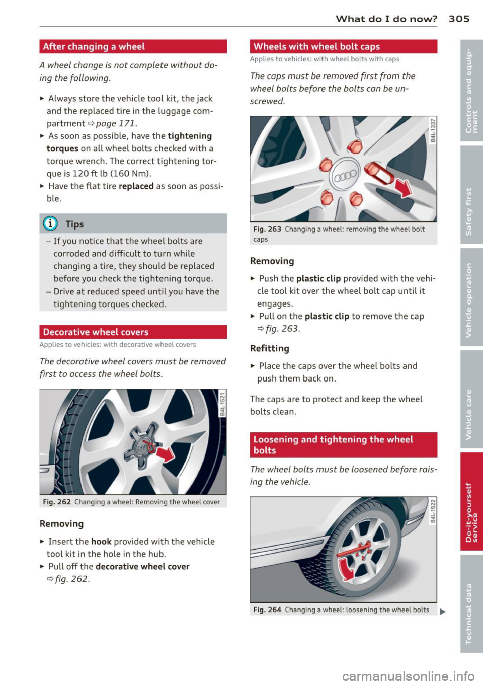
The decorative wheel covers must be removed
first to access the wheel bolts.
Fig . 262 C h ang ing a whee l: Removing the wheel cove r
Removing
• Insert the hook provided with the veh icle
tool kit in the hole in the hub.
• Pull off the
decorative wheel cover
c>fig . 262.
What do I do now? 305
Wheels with wheel bolt caps
Applies to vehicles: with wheel bolts with caps
The cops must be removed first from the
wheel bolts before the bolts can be un
screwed .
Fig. 263 Chang ing a whee l: removing the wheel bo lt
caps
Removing
• Push the plastic clip provided with the veh i
cle tool kit over the wheel bolt cap until it
engages .
• Pull on the
plastic clip to remove the cap
c>fig. 263.
Refitting
• Place the caps over the wheel bolts and
push them back on.
The caps are to protect and keep the wheel bolts clean.
Loosening and tightening the wheel
bolts
The wheel bolts must be loosened before rais
ing the vehicle.
Fig. 264 C ha ng in g a wheel : loosen ing t he whee l bol ts ...
Page 310 of 348
308 What do I do no w?
When removing or installing the wheel,
the rim could hit the brake rotor and dam
age the rotor. Work carefully and have a
second person help you.
- When mounting tires with
unid irection al
tread design
make sure the tread pat
tern is pointed the right way
¢ page 308 .
-The wheel bolts should be clean and easy
to turn. Check for d irt and corrosion on
the mat ing surfaces of both the wheel
and the hub . Remove all dirt from these
su rfaces before remount ing the wheel.
Tires with unidirectional tread design
Tires with unidirectional tread design must be
mounted with their tread pattern pointed in
the right direction.
Using a spare t ire w ith a tread pattern
int ended fo r use in a specific direct ion
When us ing a spa re tire w ith a t read patte rn
i n te nded for use in a specific direction, p lease
note the fo llowing:
- The direction of rotation is marked by an ar
row on the side of the tire .
- If the spare t ire has to be in stalled in the in
correct d irection, use the spare tire only
temporarily since the t ire will not be able to
a chieve its optimum perfo rmance character
ist ics w ith reg ard to aquapl ani ng, noise and
wea r.
- We recommend tha t you pay pa rticular at
tent ion to this fact du ring wet weather and
that you adjust your speed to ma tch road
conditions .
- Replace the fla t tire w ith a new one and
have it installed on your veh icle as soon as
poss ible to restore the handling advantages
of a unid irect iona l tire .
Notes on wheel changing
Please read t he i nfo rmat ion Q page 291 , New
tires and replacing tires and wheels
if yo u are
go ing to use a spa re tire which is different
from the tires on yo ur vehicle.
After you change a tire:
- Check the tire pressure on the spar e imm e
diately after installation .
- Ha ve the wheel bolt tightening torque
ch ecked with a torque wr ench as soon a s
po ssible by your authorized Audi deal er or
a qua lifi ed workshop.
- With steel and alloy wheel rim s, the wheel
bolt s are corre ctly tightened at a torque of
120 ft lb (160 Nm) .
- If you notice that the wheel bolts ar e cor
roded and difficult to turn while changing
a tir e, they should be repla ced before y ou
c h eck the tightening torque .
- Re pla ce the flat tire wi th a new on e and
have it in stalled on y our vehi cle a s soon a s
po ssible. Remount the wheel cover.
Until th en , dr iv e with extra car e and at re
duc ed sp eed s.
&_ WARNING
-
- If you a re going to eq uip your vehi cle
with tires or rims which differ from those
which were factory installed, then be
sure to read the information
Q page 291,
New tires and replacing tires and
wheels.
- Always make s ure the damaged wheel o r
even a flat tire and the jack and tool kit
are property secured in the luggage com
partment and are not loose in the pas
senger compartment .
- In an accident or sudden maneuver they
could fly forwa rd, injuring anyone in the
ve hicle .
- Always store damaged wheel, jack and
too ls securely in the luggage compa rt
ment. Othe rwise, in a n accident o r sud
den maneuve r they could f ly forwa rd ,
causing inj ury to passengers in the ve hi
cle .
Page 311 of 348
Fuses and bulbs
Electrical fuses
Replacing fuses
Fuses that have blown will have metal strips
that have burned through.
Fig. 268 Left cockpit: fuse panel cove r
•
•
Fig. 269 Right lu ggage compa rtment: side tr im
The fuses are located at the front left and
right of the cockpit and behind the trim on
the right side of the luggage compartment.
.. Turn off the ignit ion and the affected elec-
trical consumers.
11 You can dis pose of the pla st ic d ip afte r remov ing it.
Fuses and bulbs 309
.. Check the following table to see which fuse
be longs to the consumer.
.. Remove the appropr iate cover .
.. To remove the purp le plastic clip if necessa
ry
1> , hold onto it at the small side and pull
it out of the fuse panel
9 page 310,
fig. 270 .
.. Remove the clamp from the rear side of the
fuse cover
9 fig. 268 .
.. Remove the f use using the clamp and re
place the b lown fuse with an ident ica l new
one.
A WARNING
--
Do not repair fuses and never replace a
blown fuse with one that has a higher amp
rating. This can cause damage to the elec
tr ica l system and a fire.
(D Note
If a new fuse burns out again after short ly
have you have installed it, have the electri
cal system checked by your authorized
Audi dealer .
{!) Tips
-The following table does not list fuse lo
cat ions that are not used.
- Some of the equipment items listed are
opt ional or only available on certain
mode l configurations .
Page 316 of 348
314 Emergency situations
Emergency situations
General
This chapter is intended for trained emer
gency crews and working personnel who
have the necessary tools and equipment to perform these operations.
Starting by pushing or
towing
Q;) Note
Your vehicle is equipped with an automatic
transmission. Consequently, the engine
cannot be started by pushing or towing.
Starting with jumper
cables
If necessary, the engine can be started by
connecting it to the battery of another vehi
cle.
If the engine should fail to start because of a
discharged or weak battery, the battery can be
connected to the battery of
another vehicle,
using a
pair of jumper cables to start the en
gine .
Jumper cables
Use only jumper cables of sufficiently large
cross section to carry the starter current safe
ly. Refer to the manufacturer's specifications.
Use only jumper cables with
insulated termi
nal clamps which are distinctly marked:
plus(+) cable in most cases colored red
minus(-) cable
in most cases colored black .
A WARNING
Batteries contain electricity, acid, and gas.
Any of these can cause very serious or fatal
injury. Follow the instructions below for
safe handling of your vehicle's battery.
- Always shield your eyes and avoid lean
ing over the battery whenever possible. -
A discharged battery can freeze at tem
peratures just below 32 °F (0 °C). Before
connecting a jumper cable, you must
thaw the frozen battery completely, oth
erwise it could explode.
- Do not allow battery acid to contact eyes
or skin . Flush any contacted area with
water immediately .
- Improper use of a booster battery to
start a vehicle may cause an explosion.
- Vehicle batteries generate explosive gas
es . Keep sparks, flame and lighted ciga
rettes away from batteries.
- Do not try to jump start any vehicle with
a low acid level in the battery .
- The voltage of the booster battery must
also have a 12-Volt rating. The capacity
(Ah) of the booster battery should not be
lower than that of the discharged bat
tery . Use of batteries of different voltage
or substantially different "Ah" rating
may cause an explosion and personal in
jury.
- Never charge a frozen battery. Gas trap
ped in the ice may cause an explosion.
- Never charge or use a battery that has
been frozen. The battery case may have
be weakened.
- Use of batteries of different voltage or
substantially different capacity (Ah) rat
ing may cause an explosion and injury.
The capacity (Ah) of the booster battery
should not be lower than that of the dis
charged battery.
- Before you check anything in the engine
compartment, always read and heed all
WARNINGS¢
page 255, Engine com
partment.
@ Note
- Applying a higher voltage booster bat
tery will cause expensive damage to sen
sitive electronic components, such as
control units, relays, radio, etc.
- There must be no electrical contact be
tween the vehicles as otherwise current
could already start to flow as soon as the
positive(+) terminals are connected. ..,.
Page 318 of 348
316 Emergency sit uat ions
-Jumper cables must be long enough so
that the vehicles do not touch.
- When connecting jumper cables, make
sure that they cannot get caught in any
moving parts in the engine compart
ment.
- Before you check anything in the engine compartment, always read and heed all
WARNINGS c>
page 255, Engine com
partment.
({D Note
Improper hook-up of jumper cables can r u
in the generator.
- Always connect POSITIVE( +) to POSI
TIVE(+), and NEGATIVE( -) to NEGATIVE
( - ) ground post of the battery manager
control unit.
- Check that all screw plugs on the battery
cells are screwed in firmly. If not, tighten
plugs prior to connecting clamp on nega
tive battery terminal.
- Please note that the procedure for con
nec:t i ng a jumper cable as described
above applies spec ifically to the case of
you r vehicle being jump started. When
you are giving a jump star t to anothe r ve
hicle, do
not connect the negat ive (-) ca
ble to the negat ive (-) terminal on the
discharged battery@c>
fig. 2 74. In
stead, securely connect the negative(-)
cable to e ither a solid metal component
that is firmly bolted to the engine block
or to the engine block itse lf. If the bat
te ry that is being charged does not vent
to t he outside, escaping batte ry gas
could ignite and explode!
Emergency towing
with commercial tow
truck
General hints
Your Audi requires special handling for tow
ing.
T he following information is to be used by
commercial tow truck operators who know
how to operate their equipment safely.
- Nev er tow your Audi , towing will cau se
damage to the engine and tr an smi ssion .
- Ne ver wrap th e safety chain s or winch ca
ble s around the brak e lines.
- To pre vent unne ce ss ary damage, your Audi
mus t be tr an sp o rt ed with a flat bed tru ck.
- To load th e vehi cle on to th e flat b ed, use
the towing l oop found in the ve hicle to ols
an d att ach to th e front or rea r a ncho rage
i=> page 317 and c> page 317 .
& WARNING
--==
A vehicle being towed is not safe for pas-
sengers. Never allow anyone to ride in a
vehicle be ing towed, for any reason.
-
Page 321 of 348
fall f rom a lift if the re is a change in ve
h icle we ight d istr ibut ion and balance.
This might happen, for examp le, when
heavy components such as the engi ne
b lock or transmiss io n are removed .
- Whe n removing heavy components like
these, ancho r vehicle to ho ist o r add cor
r e spond ing w eig hts to ma intai n the cen
te r of g ravity . Othe rwise, the vehicl e
mi ght til t or slip off th e hoi st, causi ng
s er ious perso nal inju ry.
(D Note
- Be awa re of th e f ollowing po in ts b efore
li fting t he vehi cle:
- The vehicle should never be lifted or
jacked up from underneath the engine oil pan, the transmission housing, the
front or rear axle or the body side
members. This could lead to serious
damage .
- To avoid damage to the underbody or
chassis frame, a rubber pad must be
inserted between the floor jack and
the lift points.
- Before driving over a workshop hoist,
check that the vehicle weight does not
exceed the permissible lifting capacity
of the hoist.
- Before driving over a workshop hoist,
ensure that there is sufficient clear ance between the hoist and low parts
of the vehicle .
Emergency situations 319
•
•
Page 322 of 348
320 General information
General information Explanation of
technical data
Some of the technical data listed in this man
ual requires further explanation .
The technical data for your vehicle is listed in
the charts starting on
r:::>page 322. This sec
tion provides general information, notes and
restrictions which apply to this data .
Vehicle identification
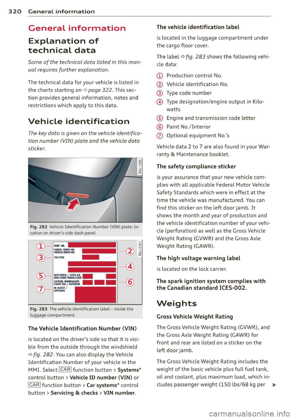
The key data is given on the vehicle identifica
tion number (VIN) plate and the vehicle data
sticker.
Fig. 282 Veh icle Ide ntific atio n Number (VlN) p late: lo
cation on driver 's sid e das h panel
Fig. 283 The vehicle identi fication label -inside the
luggage co mpa rtmen t
The Vehicle Identification Number (VIN)
is located on the driver's side so that it is visi
b le from the outside through the windshield
r:::> fig . 282 . You can also display the Vehicle
Identification Number of your vehicle in the
MMI. Select !CAR lfunc tion button>
Systems*
control button > Vehicle ID number (V IN) or
ICARI function button >
Car systems * control
button >
Servicing & checks > VIN number . The
vehicle identification label
is located in the luggage compartment under
the cargo floor cover.
The label¢
fig. 283 shows the following vehi
cle data :
(D Production control No .
@ Vehicle identification No.
® Type code number
@ Type designation/engine output in Kilo-
watts
® Engine and transmission code letter
@ Paint No./Interior
(f) Optional equipment No.'s
Vehicle data 2 to 7 are also found in your War
ranty
& Maintenance booklet.
The safety compliance sticker
is you r assurance that your new vehicle com
plies with all applicable Federal Motor Vehicle
Safety Standards which were in effect at the
time the vehicle was manufactured . You can
find this sticker on the left door jamb.
It
shows the month and year of production and
the ve hicle ident ification number of your vehi
cle (perforation) as well as the Gross Vehicle
Weight Rating (GVWR) and the Gross Axle
Weight Rating (GAWR) .
The high voltage warning label
is located on the lock carr ier .
The spark ignition system complies with
the Canadian standard ICES-002.
Weights
Gross Vehicle Weight Rating
The Gross Vehicle Weight Rating (GVWR), and
the Gross Axle Weight Rating (GAWR) for
front and rear are Listed on a sticker on the
left door jamb.
The Gross Vehicle Weight Rating includes the
weight of the basic vehicle plus full fuel tank,
oi l and coolant, plus maximum load, wh ich in
cludes passenger weight (lSO lbs/68 kg per
Ill>