engine AUDI S4 1998 B5 / 1.G Engine Manual
[x] Cancel search | Manufacturer: AUDI, Model Year: 1998, Model line: S4, Model: AUDI S4 1998 B5 / 1.GPages: 72, PDF Size: 3.25 MB
Page 13 of 72
13
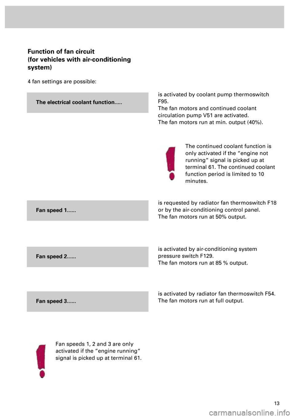
Function of fan circuit
(for vehicles with air-conditioning
system)
4 fan settings are possible:
is activated by coolant pump thermoswitch
F95.
The fan motors and continued coolant
circulation pump V51 are activated.
The fan motors run at min. output (40%).
is requested by radiator fan thermoswitch F18
or by the air-conditioning control panel.
The fan motors run at 50% output.
is activated by air-conditioning system
pressure switch F129.
The fan motors run at 85 % output.
is activated by radiator fan thermoswitch F54.
The fan motors run at full output.
Fan speeds 1, 2 and 3 are only
activated if the “engine running“
signal is picked up at terminal 61.
The electrical coolant function.....
The continued coolant function is
only activated if the “engine not
running“ signal is picked up at
terminal 61. The continued coolant
function period is limited to 10
minutes.
Fan speed 1......
Fan speed 2......
Fan speed 3......
Page 14 of 72
1415
SSP 198/49
Engine
Engine lubrication
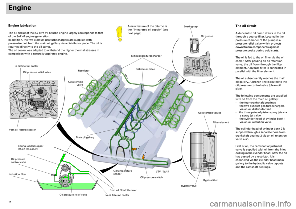
The oil circuit of the 2.7-litre V6 biturbo engine largely corresponds to that
of the 3rd V6 engine generation.
In addition, the two exhaust gas turbochargers are supplied with
pressurised oil from the main oil gallery via a distributor piece. The oil is
returned directly to the oil sump.
The oil cooler was adapted to withstand the higher thermal stresses in
comparison with a naturally aspirated engine.A new feature of the biturbo is
the “integrated oil supply“ (see
next page).
to oil filter/oil cooler
Spring-loaded slipper
(chain tensioner)
Main oil gallery
Oil retention valves
Bypass valve
Filter element
Bearing cap
Oil groove
Oil temperature
sender
Oil pressure switch
Restrictor
Oil retention
valve
distributor piece
The oil circuit
A duocentric oil pump draws in the oil
through a coarse filter. Located in the
pressure chamber of the pump is a
pressure relief valve which protects
downstream components against
pressure peaks during cold starts.
The oil is fed to the oil filter via the oil
cooler. After passing an oil retention
valve, the oil flows through the filter
element. A bypass filter is connected in
parallel with the filter element.
The oil subsequently reaches the main
oil gallery. A branch line is routed to the
oil pressure control valve (clean oil
side).
The following components are supplied
with oil from the main oil gallery:
- the four crankshaft bearings
- the two exhaust gas turbochargers
via an oil distributor line
- the three pairs of piston spray jets via
a spray jet valve
- the cylinder head of cylinder bank 1
via an oil retention valve
The cylinder head of cylinder bank 2 is
supplied through a separate bore from
crankshaft bearing 2 via an oil retention
valve also.
First of all, the camshaft adjustment
valve is supplied with oil from the inlet
drilling in the cylinder head. After the oil
has passed by a restrictor, it is
channeled via the cylinder head main
gallery to the hydraulic valve tappets
and the camshaft bearings.
Exhaust gas turbocharger
Bypass filter
Oil pressure relief valve
from oil filter/oil coolerOil pressure
control valveInduction filter
Oil pressure relief valve
from oil filter/oil cooler
to oil filter/oil cooler
Page 15 of 72
16
Engine
The component parts of the oil circuit
is integrated in the primary flow. By increasing
the capacity and optimising the flow
resistance, the entire oil flow can be routed
through the oil cooler. Unlike the V6 naturally
aspirated engine, a bypass is not required.
The oil cooler ......
contains an oil retention valve, the filter
element, a bypass filter and the filter bypass
valve. The latter has the task of maintaining
engine lubrication via the bypass filter if the
filter element becomes clogged up or if the oil
has a high viscosity.
The oil filter ......
opens up the oil flow to the piston spray jets if
the oil pressure is greater than 1.8 bar.
Reason: at low oil viscosity and low engine
speeds, the oil pressure would otherwise drop
below the minimum permissible level. That
aside, piston cooling is not necessary at low
engine speeds.
The spray jets valve ......
SSP 198/57
Oil pressure control valve
Oil pressure limiting valve
Chain guard
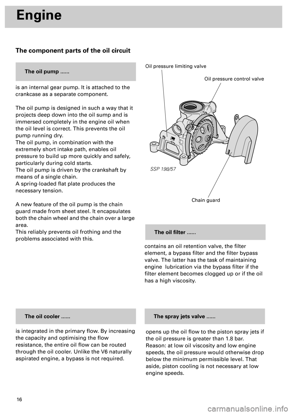
is an internal gear pump. It is attached to the
crankcase as a separate component.
The oil pump is designed in such a way that it
projects deep down into the oil sump and is
immersed completely in the engine oil when
the oil level is correct. This prevents the oil
pump running dry.
The oil pump, in combination with the
extremely short intake path, enables oil
pressure to build up more quickly and safely,
particularly during cold starts.
The oil pump is driven by the crankshaft by
means of a single chain.
A spring-loaded flat plate produces the
necessary tension.
A new feature of the oil pump is the chain
guard made from sheet steel. It encapsulates
both the chain wheel and the chain over a large
area.
This reliably prevents oil frothing and the
problems associated with this.
The oil pump ......
Page 16 of 72
17
is a pressure relief valve. It is located inside the
oil pump housing and opens when the oil
pressure rises too high (cold start). If an
excessively high oil pressure builds up,
various component parts of the oil circuit (e.g.
oil filter, oil cooler) may be damaged. Also,
there is the possibility of the inlet and exhaust
valves opening or no longer closing, due to
“bulking“ of the hydraulic tappets. The knock-
on effect of this is that the engine can no
longer be started or cuts out.
The oil pressure limiting valve ......
regulates the engine oil pressure. It is
integrated in the oil pump housing. The oil
quantity “regulated“ by the oil pressure
control valve is fed to the suction side of the
oil pump.
This helps to optimise efficiency.
The oil pressure control valve ......
prevent the oil running out of the oil filter and
the cylinder heads and back into the oil sump
while the engine is stationary.
The oil retention valves ......
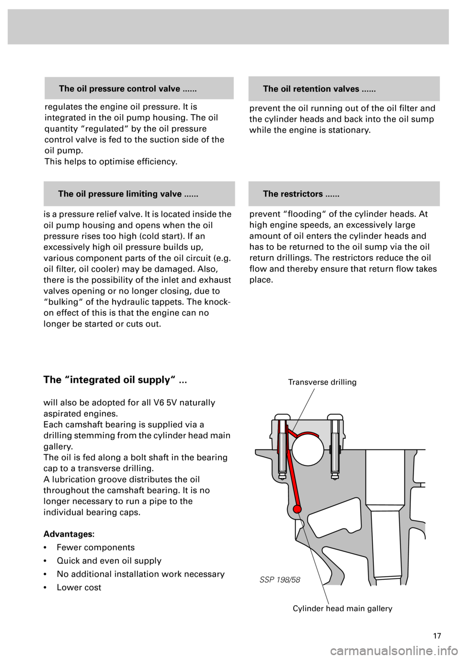
The “integrated oil supply“ ...
will also be adopted for all V6 5V naturally
aspirated engines.
Each camshaft bearing is supplied via a
drilling stemming from the cylinder head main
gallery.
The oil is fed along a bolt shaft in the bearing
cap to a transverse drilling.
A lubrication groove distributes the oil
throughout the camshaft bearing. It is no
longer necessary to run a pipe to the
individual bearing caps.
Advantages:
•
Fewer components
•
Quick and even oil supply
•
No additional installation work necessary
•
Lower cost
SSP 198/58
Cylinder head main gallery
Transverse drilling
prevent “flooding“ of the cylinder heads. At
high engine speeds, an excessively large
amount of oil enters the cylinder heads and
has to be returned to the oil sump via the oil
return drillings. The restrictors reduce the oil
flow and thereby ensure that return flow takes
place.
The restrictors ......
Page 17 of 72
18
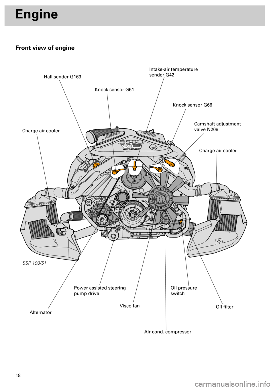
Front view of engine
SSP 198/51
Engine
Camshaft adjustment
valve N208
Knock sensor G66
Intake-air temperature
sender G42
Knock sensor G61
Hall sender G163
Charge air cooler
Charge air cooler
Oil filter
Oil pressure
switch
Air-cond. compressor
Visco fan
Alternator
Power assisted steering
pump drive
Page 18 of 72
19
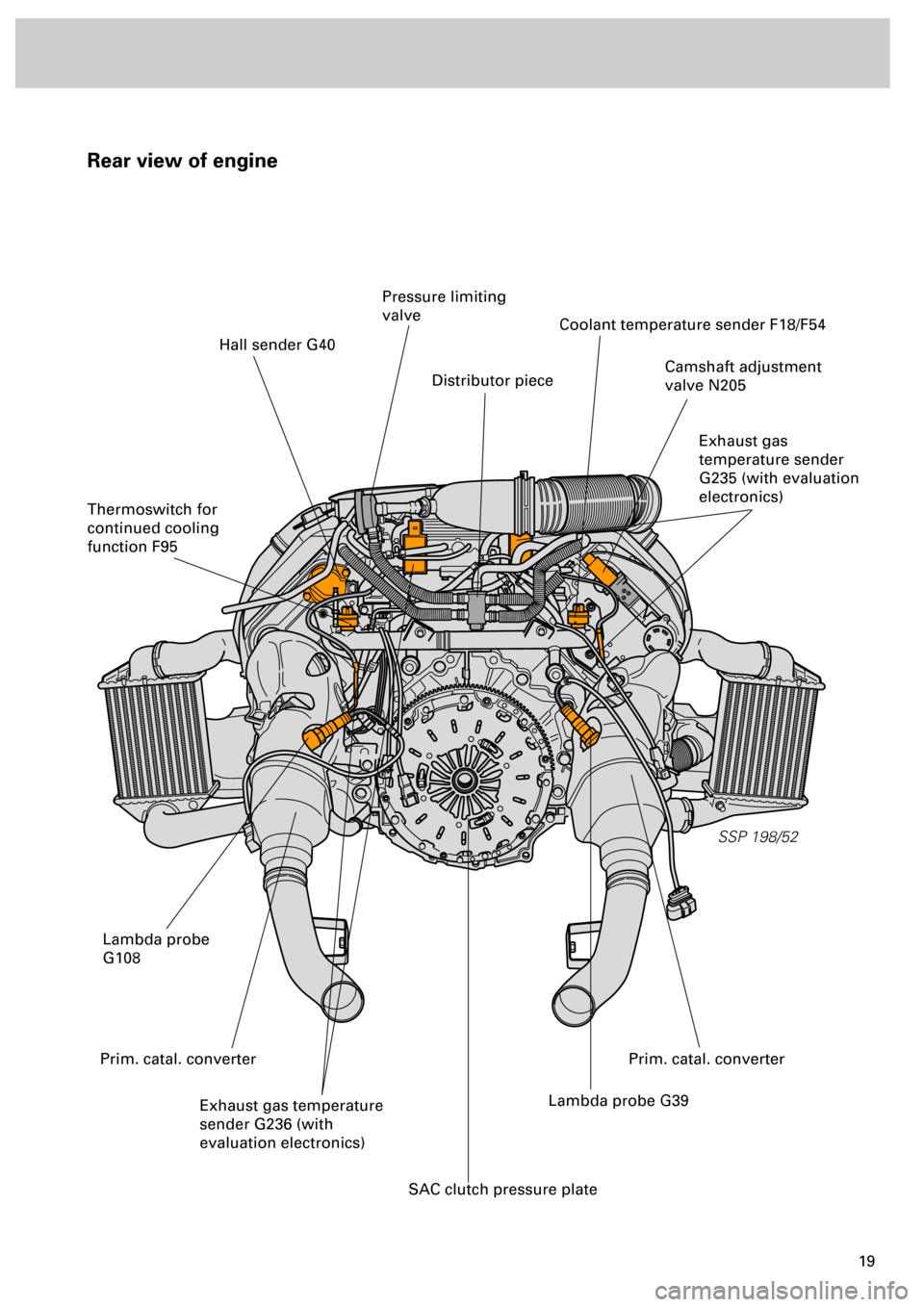
Rear view of engine
SSP 198/52
Hall sender G40
Thermoswitch for
continued cooling
function F95
Pressure limiting
valve
Distributor piece
Coolant temperature sender F18/F54
Camshaft adjustment
valve N205
Exhaust gas
temperature sender
G235 (with evaluation
electronics)
Lambda probe
G108
Exhaust gas temperature
sender G236 (with
evaluation electronics)Lambda probe G39
SAC clutch pressure plate
Prim. catal. converterPrim. catal. converter
Page 19 of 72
20
Engine
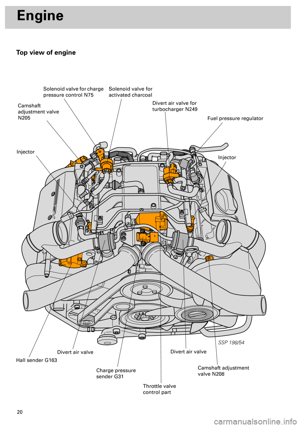
Top view of engine
SSP 198/54
Divert air valve for
turbocharger N249
Injector
Fuel pressure regulator
Solenoid valve for
activated charcoal Solenoid valve for charge
pressure control N75
Camshaft
adjustment valve
N205
Injector
Hall sender G163
Divert air valve
Charge pressure
sender G31
Throttle valve
control part
Camshaft adjustment
valve N208
Divert air valve
Page 20 of 72
21
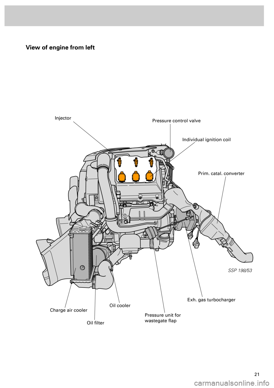
View of engine from left
SSP 198/53
Injector
Individual ignition coil
Pressure control valve
Prim. catal. converter
Exh. gas turbocharger
Pressure unit for
wastegate flap
Oil cooler
Oil filter
Charge air cooler
Page 21 of 72
22
SSP 198/04
Engine
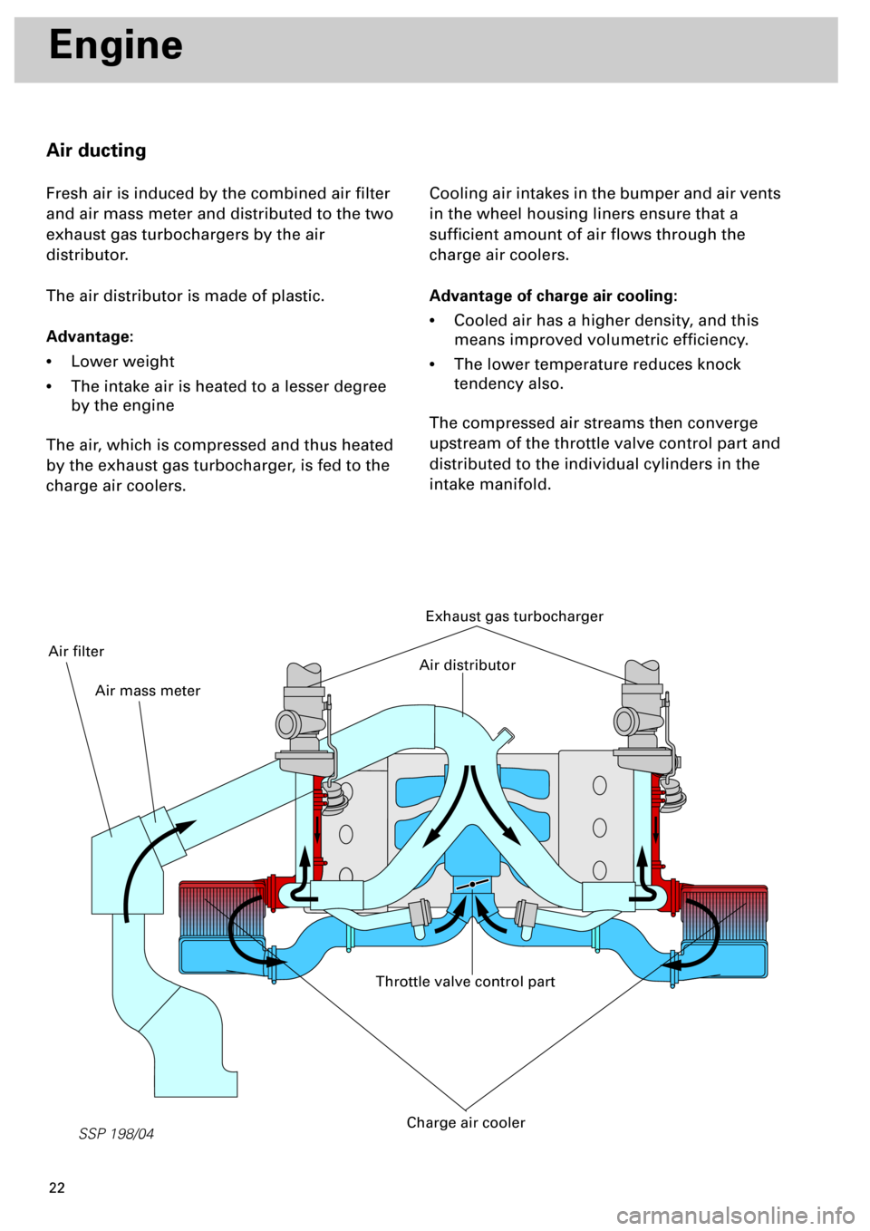
Air ducting
Fresh air is induced by the combined air filter
and air mass meter and distributed to the two
exhaust gas turbochargers by the air
distributor.
The air distributor is made of plastic.
Advantage:
•
Lower weight
•
The intake air is heated to a lesser degree
by the engine
The air, which is compressed and thus heated
by the exhaust gas turbocharger, is fed to the
charge air coolers.Cooling air intakes in the bumper and air vents
in the wheel housing liners ensure that a
sufficient amount of air flows through the
charge air coolers.
Advantage of charge air cooling:
•
Cooled air has a higher density, and this
means improved volumetric efficiency.
•
The lower temperature reduces knock
tendency also.
The compressed air streams then converge
upstream of the throttle valve control part and
distributed to the individual cylinders in the
intake manifold.
Exhaust gas turbocharger
Throttle valve control part
Charge air cooler
Air distributor
Air mass meter
Air filter
Page 22 of 72
23
SSP 198/32
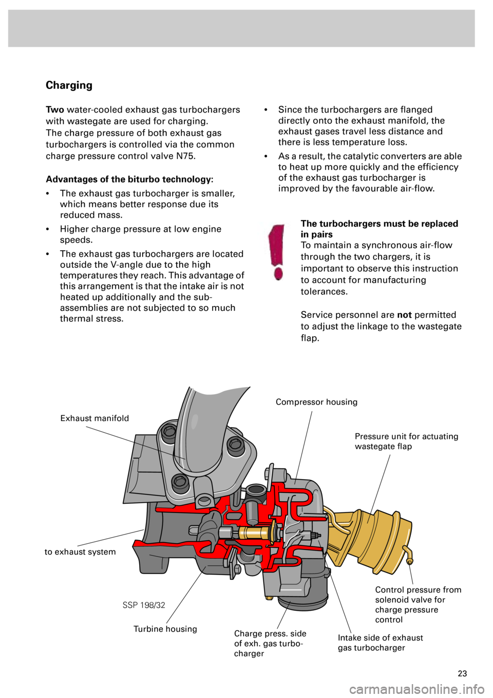
Charging
Two
water-cooled exhaust gas turbochargers
with wastegate are used for charging.
The charge pressure of both exhaust gas
turbochargers is controlled via the common
charge pressure control valve N75.
Advantages of the biturbo technology:
•
The exhaust gas turbocharger is smaller,
which means better response due its
reduced mass.
•
Higher charge pressure at low engine
speeds.
•
The exhaust gas turbochargers are located
outside the V-angle due to the high
temperatures they reach. This advantage of
this arrangement is that the intake air is not
heated up additionally and the sub-
assemblies are not subjected to so much
thermal stress.
•
Since the turbochargers are flanged
directly onto the exhaust manifold, the
exhaust gases travel less distance and
there is less temperature loss.
•
As a result, the catalytic converters are able
to heat up more quickly and the efficiency
of the exhaust gas turbocharger is
improved by the favourable air-flow.
Intake side of exhaust
gas turbocharger
Charge press. side
of exh. gas turbo-
charger
Exhaust manifold
to exhaust system
Pressure unit for actuating
wastegate flap
Control pressure from
solenoid valve for
charge pressure
control
The turbochargers must be replaced
in pairs
To maintain a synchronous air-flow
through the two chargers, it is
important to observe this instruction
to account for manufacturing
tolerances.
Service personnel are
not
permitted
to adjust the linkage to the wastegate
flap.
Turbine housing
Compressor housing