engine AUDI S4 1998 B5 / 1.G Engine Manual
[x] Cancel search | Manufacturer: AUDI, Model Year: 1998, Model line: S4, Model: AUDI S4 1998 B5 / 1.GPages: 72, PDF Size: 3.25 MB
Page 23 of 72
24
SSP 198/33
Engine
A new generation of probes is used
in this engine.
The “planar lambda probe“ is an
improvement on the finger-type
lambda probe (refer to chapter on
“Sensors”).
Advantage:
•
Short warm-up time
•
Less heating energy demand
•
Long service life
•
More stable control
characteristic
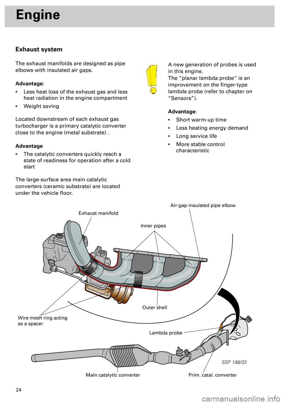
Exhaust system
The exhaust manifolds are designed as pipe
elbows with insulated air gaps.
Advantage:
•
Less heat loss of the exhaust gas and less
heat radiation in the engine compartment
•
Weight saving
Located downstream of each exhaust gas
turbocharger is a primary catalytic converter
close to the engine (metal substrate) .
Advantage
•
The catalytic converters quickly reach a
state of readiness for operation after a cold
start
The large-surface area main catalytic
converters (ceramic substrate) are located
under the vehicle floor.
Lambda probe
Prim. catal. converterMain catalytic converter
Exhaust manifold
Wire mesh ring acting
as a spacer
Air-gap-insulated pipe elbow
Outer shell
Inner pipes
Page 24 of 72
25
SSP 198/31
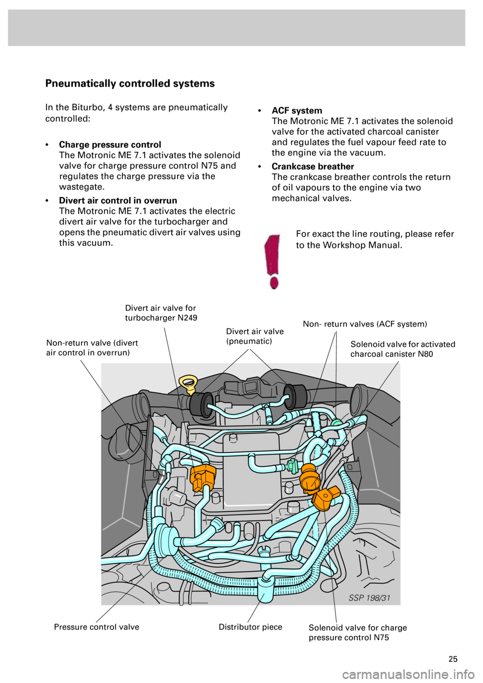
Pneumatically controlled systems
In the Biturbo, 4 systems are pneumatically
controlled:
•
Charge pressure control
The Motronic ME 7.1 activates the solenoid
valve for charge pressure control N75 and
regulates the charge pressure via the
wastegate.
•
Divert air control in overrun
The Motronic ME 7.1 activates the electric
divert air valve for the turbocharger and
opens the pneumatic divert air valves using
this vacuum.
•
ACF system
The Motronic ME 7.1 activates the solenoid
valve for the activated charcoal canister
and regulates the fuel vapour feed rate to
the engine via the vacuum.
•
Crankcase breather
The crankcase breather controls the return
of oil vapours to the engine via two
mechanical valves.
Solenoid valve for charge
pressure control N75
Solenoid valve for activated
charcoal canister N80
Divert air valve for
turbocharger N249
Non- return valves (ACF system)
Distributor piecePressure control valve
Non-return valve (divert
air control in overrun)
Divert air valve
(pneumatic)
For exact the line routing, please refer
to the Workshop Manual.
Page 25 of 72
26
SSP 198/08
Engine
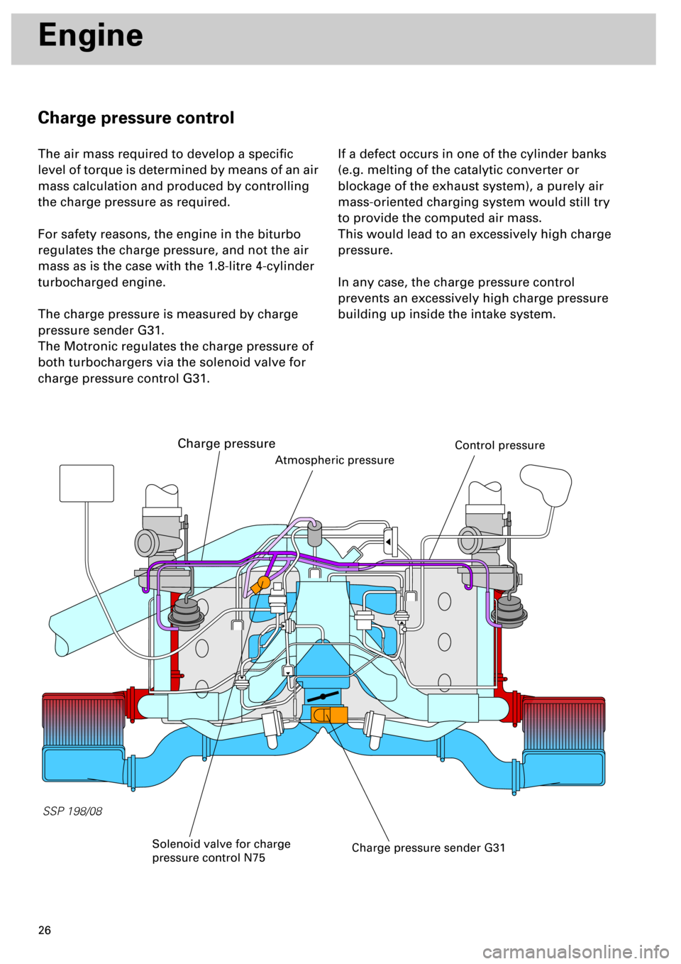
Charge pressure control
The air mass required to develop a specific
level of torque is determined by means of an air
mass calculation and produced by controlling
the charge pressure as required.
For safety reasons, the engine in the biturbo
regulates the charge pressure, and not the air
mass as is the case with the 1.8-litre 4-cylinder
turbocharged engine.
The charge pressure is measured by charge
pressure sender G31.
The Motronic regulates the charge pressure of
both turbochargers via the solenoid valve for
charge pressure control G31.
If a defect occurs in one of the cylinder banks
(e.g. melting of the catalytic converter or
blockage of the exhaust system), a purely air
mass-oriented charging system would still try
to provide the computed air mass.
This would lead to an excessively high charge
pressure.
In any case, the charge pressure control
prevents an excessively high charge pressure
building up inside the intake system.
Charge pressure sender G31
Atmospheric pressure
Solenoid valve for charge
pressure control N75
Charge pressure
Control pressure
Page 26 of 72
27
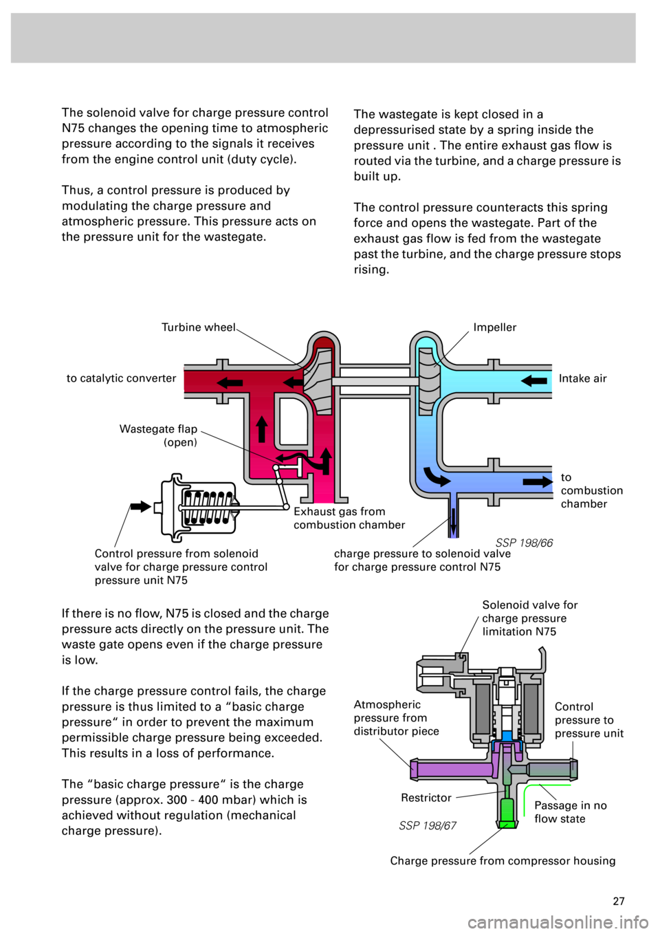
The solenoid valve for charge pressure control
N75 changes the opening time to atmospheric
pressure according to the signals it receives
from the engine control unit (duty cycle).
Thus, a control pressure is produced by
modulating the charge pressure and
atmospheric pressure. This pressure acts on
the pressure unit for the wastegate.
The wastegate is kept closed in a
depressurised state by a spring inside the
pressure unit . The entire exhaust gas flow is
routed via the turbine, and a charge pressure is
built up.
The control pressure counteracts this spring
force and opens the wastegate. Part of the
exhaust gas flow is fed from the wastegate
past the turbine, and the charge pressure stops
rising.
If there is no flow, N75 is closed and the charge
pressure acts directly on the pressure unit. The
waste gate opens even if the charge pressure
is low.
If the charge pressure control fails, the charge
pressure is thus limited to a “basic charge
pressure“ in order to prevent the maximum
permissible charge pressure being exceeded.
This results in a loss of performance.
The “basic charge pressure“ is the charge
pressure (approx. 300 - 400 mbar) which is
achieved without regulation (mechanical
charge pressure).
SSP 198/66
Turbine wheel
to catalytic converter
Impeller
Exhaust gas from
combustion chamber
Wastegate flap
(open)
Control pressure from solenoid
valve for charge pressure control
pressure unit N75charge pressure to solenoid valve
for charge pressure control N75
Intake air
to
combustion
chamber
SSP 198/67
Atmospheric
pressure from
distributor piece
Solenoid valve for
charge pressure
limitation N75
Charge pressure from compressor housing
RestrictorPassage in no
flow state
Control
pressure to
pressure unit
Page 27 of 72
28
SSP 198/05
Engine
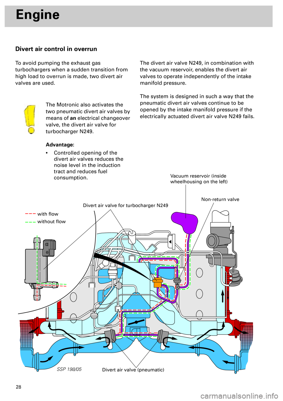
Divert air control in overrun
To avoid pumping the exhaust gas
turbochargers when a sudden transition from
high load to overrun is made, two divert air
valves are used.
The Motronic also activates the
two pneumatic divert air valves by
means of
an
electrical changeover
valve, the divert air valve for
turbocharger N249.
Advantage:
•
Controlled opening of the
divert air valves reduces the
noise level in the induction
tract and reduces fuel
consumption.
The divert air valve N249, in combination with
the vacuum reservoir, enables the divert air
valves to operate independently of the intake
manifold pressure.
The system is designed in such a way that the
pneumatic divert air valves continue to be
opened by the intake manifold pressure if the
electrically actuated divert air valve N249 fails.
Divert air valve for turbocharger N249
Vacuum reservoir (inside
wheelhousing on the left)
Divert air valve (pneumatic)
with flow
without flow
Non-return valve
Page 28 of 72
29
SSP 198/06
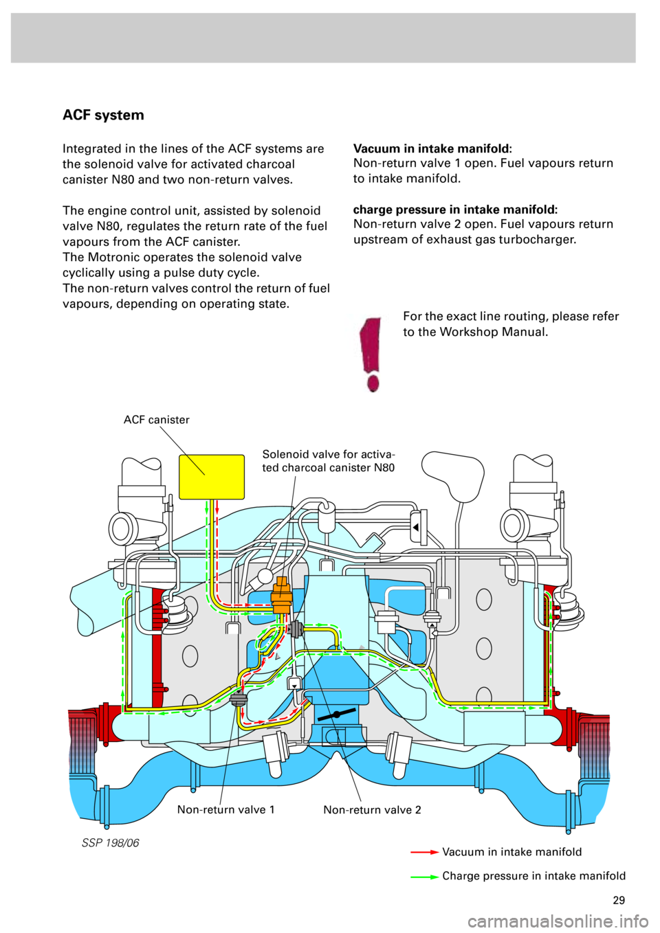
Vacuum in intake manifold:
Non-return valve 1 open. Fuel vapours return
to intake manifold.
charge pressure in intake manifold:
Non-return valve 2 open. Fuel vapours return
upstream of exhaust gas turbocharger.
ACF system
Integrated in the lines of the ACF systems are
the solenoid valve for activated charcoal
canister N80 and two non-return valves.
The engine control unit, assisted by solenoid
valve N80, regulates the return rate of the fuel
vapours from the ACF canister.
The Motronic operates the solenoid valve
cyclically using a pulse duty cycle.
The non-return valves control the return of fuel
vapours, depending on operating state.
ACF canister
Solenoid valve for activa-
ted charcoal canister N80
Non-return valve 2Non-return valve 1
Vacuum in intake manifold
Charge pressure in intake manifold
For the exact line routing, please refer
to the Workshop Manual.
Page 29 of 72
30
SSP 198/07
Engine
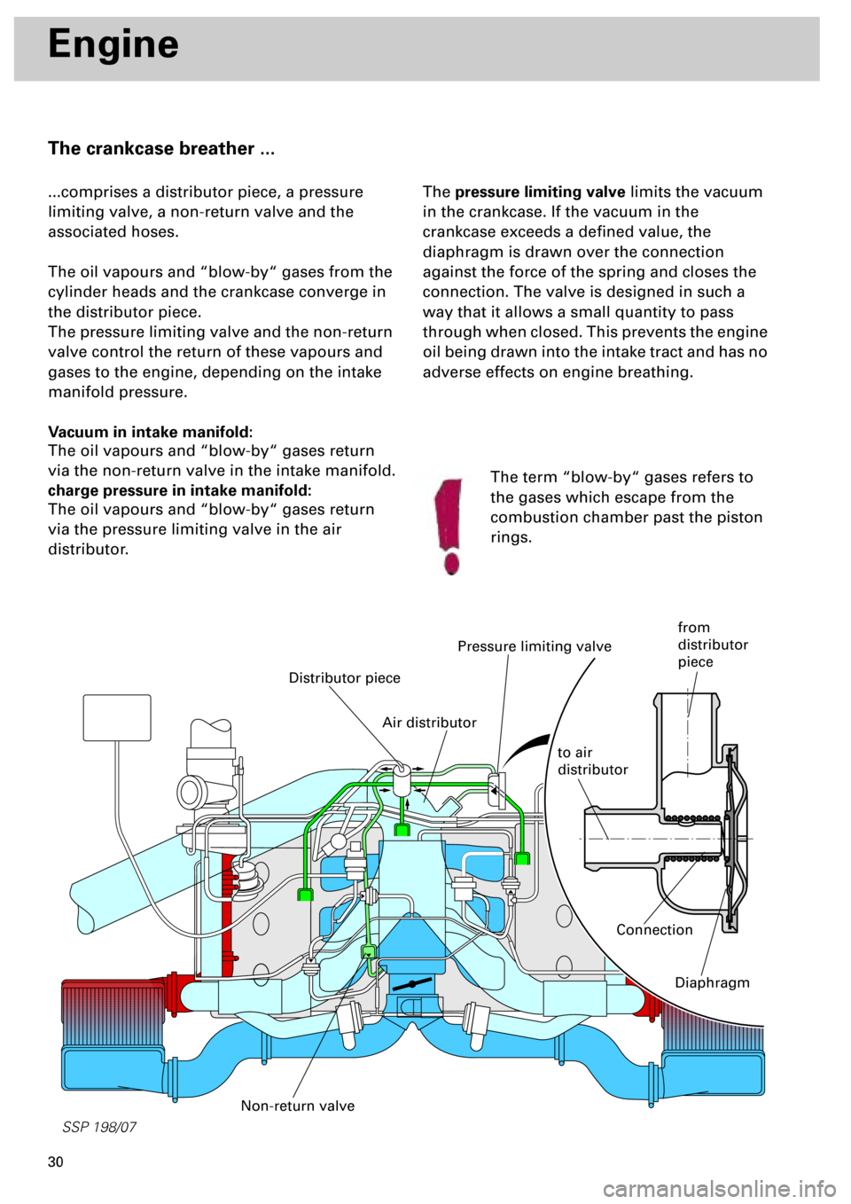
The crankcase breather ...
...comprises a distributor piece, a pressure
limiting valve, a non-return valve and the
associated hoses.
The oil vapours and “blow-by“ gases from the
cylinder heads and the crankcase converge in
the distributor piece.
The pressure limiting valve and the non-return
valve control the return of these vapours and
gases to the engine, depending on the intake
manifold pressure.
Vacuum in intake manifold:
The oil vapours and “blow-by“ gases return
via the non-return valve in the intake manifold.
charge pressure in intake manifold:
The oil vapours and “blow-by“ gases return
via the pressure limiting valve in the air
distributor.The pressure limiting valve limits the vacuum
in the crankcase. If the vacuum in the
crankcase exceeds a defined value, the
diaphragm is drawn over the connection
against the force of the spring and closes the
connection. The valve is designed in such a
way that it allows a small quantity to pass
through when closed. This prevents the engine
oil being drawn into the intake tract and has no
adverse effects on engine breathing.
Distributor piece
Pressure limiting valve
Non-return valve
The term “blow-by“ gases refers to
the gases which escape from the
combustion chamber past the piston
rings.
Connection
Diaphragm
Air distributor
to air
distributor
from
distributor
piece
Page 30 of 72
31
Motronic ME 7.1
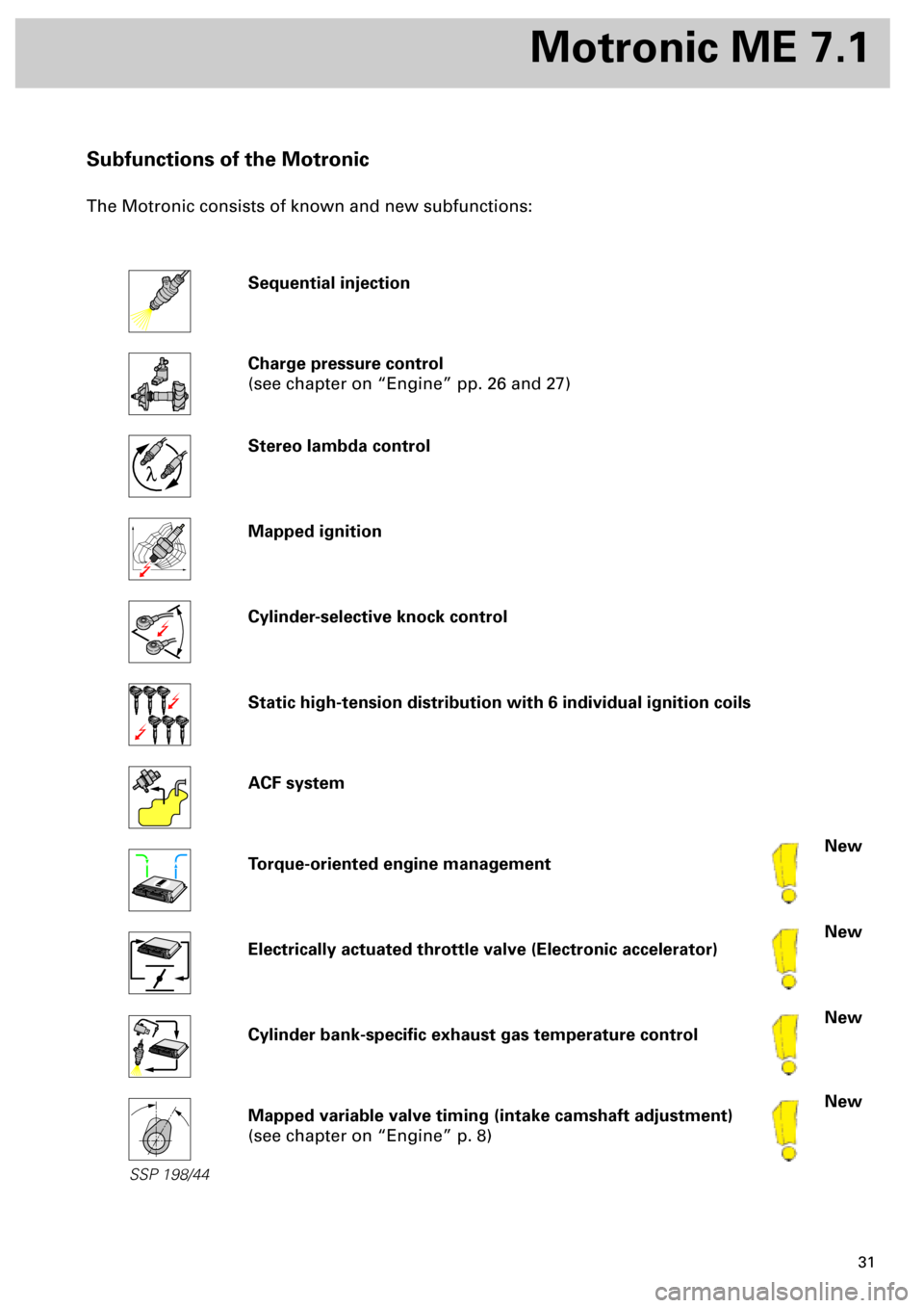
Subfunctions of the Motronic
The Motronic consists of known and new subfunctions:
Sequential injection
Charge pressure control
(see chapter on “Engine” pp. 26 and 27)
Stereo lambda control
Mapped ignition
Cylinder-selective knock control
Static high-tension distribution with 6 individual ignition coils
ACF system
Torque-oriented engine management
Electrically actuated throttle valve (Electronic accelerator)
Cylinder bank-specific exhaust gas temperature control
Mapped variable valve timing (intake camshaft adjustment)
(see chapter on “Engine” p. 8)
New
New
New
New
l
SSP 198/44
Page 31 of 72
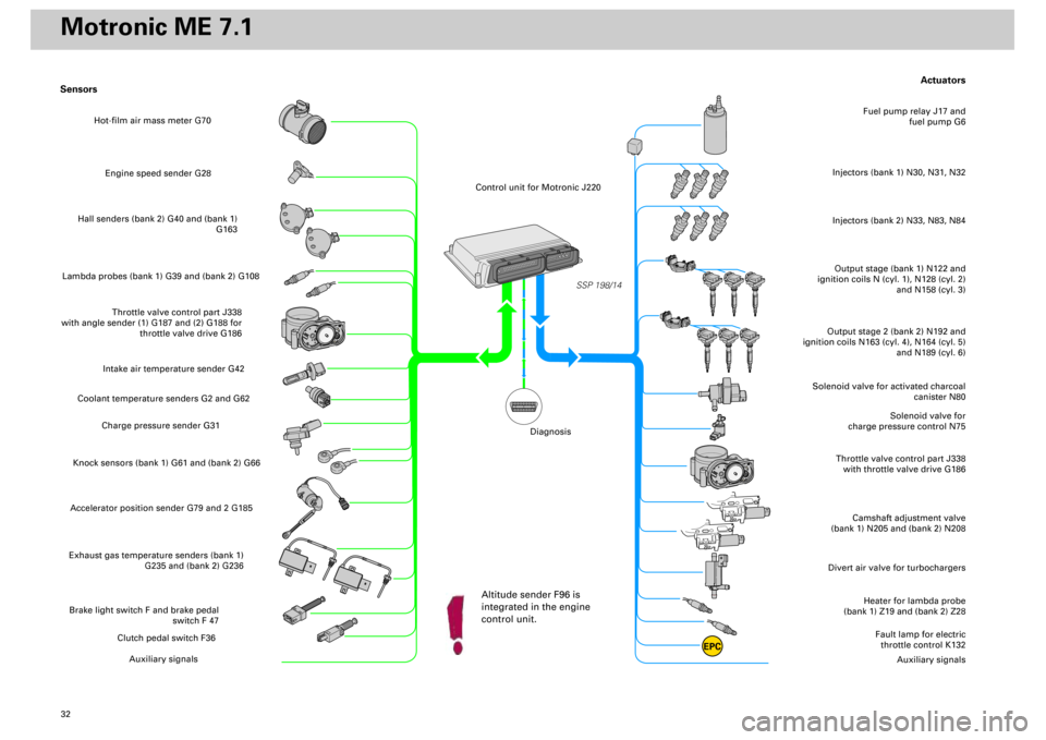
32
Actuators
Heater for lambda probe
(bank 1) Z19 and (bank 2) Z28
Divert air valve for turbochargers
Camshaft adjustment valve
(bank 1) N205 and (bank 2) N208
Throttle valve control part J338
with throttle valve drive G186
Solenoid valve for
charge pressure control N75
Solenoid valve for activated charcoal
canister N80
Output stage (bank 1) N122 and
ignition coils N (cyl. 1), N128 (cyl. 2)
and N158 (cyl. 3)Injectors (bank 1) N30, N31, N32
Fuel pump relay J17 and
fuel pump G6
Output stage 2 (bank 2) N192 and
ignition coils N163 (cyl. 4), N164 (cyl. 5)
and N189 (cyl. 6)
Fault lamp for electric
throttle control K132
Auxiliary signals
Sensors
Engine speed sender G28
Hall senders (bank 2) G40 and (bank 1)
G163
Lambda probes (bank 1) G39 and (bank 2) G108
Throttle valve control part J338
with angle sender (1) G187 and (2) G188 for
throttle valve drive G186
Intake air temperature sender G42
Coolant temperature senders G2 and G62
Charge pressure sender G31
Knock sensors (bank 1) G61 and (bank 2) G66Accelerator position sender G79 and 2 G185Exhaust gas temperature senders (bank 1)
G235 and (bank 2) G236Brake light switch F and brake pedal
switch F 47
Clutch pedal switch F36
Auxiliary signals
SSP 198/14
EPC
Injectors (bank 2) N33, N83, N84
Hot-film air mass meter G70
Control unit for Motronic J220
Altitude sender F96 is
integrated in the engine
control unit.
Diagnosis
Motronic ME 7.1
Page 32 of 72
33
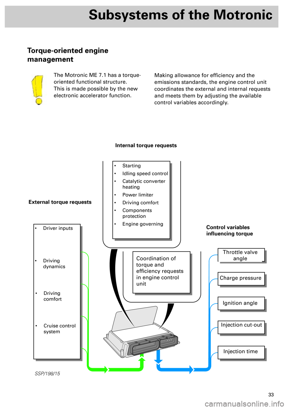
SSP/198/15
Subsystems of the Motronic
Making allowance for efficiency and the
emissions standards, the engine control unit
coordinates the external and internal requests
and meets them by adjusting the available
control variables accordingly.
Torque-oriented engine
management
The Motronic ME 7.1 has a torque-
oriented functional structure.
This is made possible by the new
electronic accelerator function.
Internal torque requests
External torque requests
• Starting
• Idling speed control
• Catalytic converter
heating
• Power limiter
• Driving comfort
• Components
protection
• Engine governing
• Driver inputs
Throttle valve
angle
Charge pressure
Ignition angle
Injection cut-out
Injection time
Control variables
influencing torque
• Driving
dynamics
• Driving
comfort
• Cruise control
system
Coordination of
torque and
efficiency requests
in engine control
unit