AUDI TT COUPE 2009 Owners Manual
Manufacturer: AUDI, Model Year: 2009, Model line: TT COUPE, Model: AUDI TT COUPE 2009Pages: 316, PDF Size: 71.16 MB
Page 271 of 316
_______________________________________________ W_ h_ a _ t_d_ o_ l _d _o_ n_ o_ w_ ? _ __.ffllll
Ap plies to vehic les: with decorative wheel covers
Decorative wheel covers
The decorative wheel covers must be removed first to
access the wheel bolts.
Removing
Fig . 161 Wheel
change : removing the
wheel cover
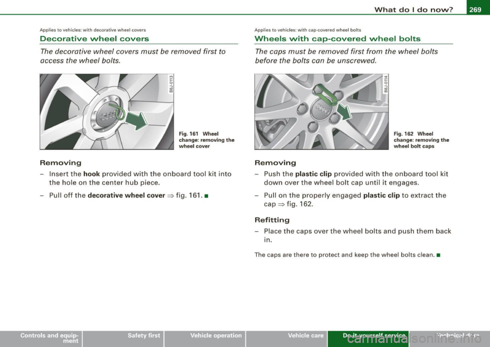
- Insert the hook provided with the on board tool kit into
the hole on the center hub piece.
- Pull off the
decorative wheel cover=> fig. 161. •
Applies to vehicles: with cap-covered wheel bolts
Wheels with cap-covered wheel bo lts
The caps must be removed first from the wheel bolts
before the bolts can be unscrewed.
Removing
Fig . 162 Wheel
change : removing the
wheel bolt caps
-Push the plastic clip provided with the on board tool kit
down over the wheel bolt cap until it engages.
- Pull on the properly engaged
plastic clip to extract the
cap=> fig. 162.
Refitting
-Place the caps over the wheel bo lts and push them back
1n.
The caps are there to protect and keep the wheel bolts clean.•
Vehicle care Do-it-yourself service irechnical data
Page 272 of 316
1111...__W_ h_ a _ t_d_ o_ l _d _o_ n_ o_ vv_ ? ______________________________________________ _
Loosening and tightening the wheel bolts
The wheel bolts must be loosened before raising the
vehicle.
Loosening
Fig . 163 Wheel
change: loosening the
wheel bolts
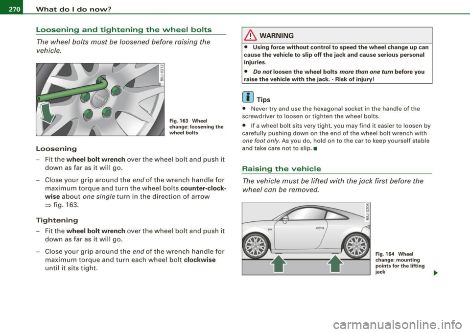
- Fit the wheel bolt wrench over the wheel bolt and push it
down as far as it will go .
- Close your grip around the
end of the wrench handle for
maximum torque and turn the wheel bolts
counter-clock
wise
about one single turn in the direction of arrow
~ fig. 163.
Tightening
Fit the wheel bolt wrench over the wheel bolt and push it
down as far as it will go.
- Close your grip around the
end of the wrench handle for
maximum torque and turn each wheel bolt
clockwise
until it sits tight.
& WARNING
• Using force without control to speed the wheel change up can
cause the vehicle to slip off the jack and cause serious personal
injuries.
• Do not loosen the wheel bolts more than one turn before you
raise the vehicle with the jack. -Risk of injury!
[ i] Tips
• Never try and use the hexagonal socket in the handle of the
screwdriver to loosen or tighten the wheel bolts.
• If a wheel bolt sits very tight, you may find it easier to loosen by
carefully pushing down on the end of the wheel bolt wrench with
one foot only . As you do, hold on to the car to keep yourself stable
and take care not to slip.•
Raising the vehicle
The vehicle must be lifted with the jack first before the
wheel can be removed.
Fig. 164 Wheel
change: mounting
points
for the lifting
jack ..
Page 273 of 316
What do I do now? -
------------------
Fig. 165 Close-up:
proper positioning of
lifting jack
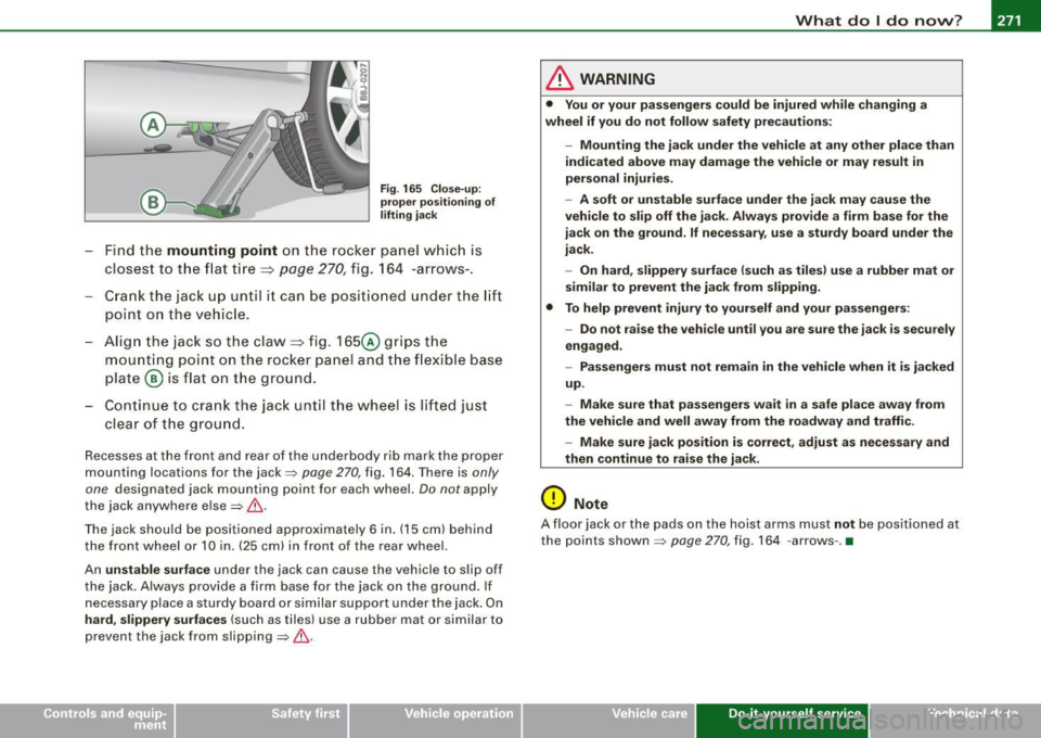
- Find the mounting point on the rocker panel which is
closest to the flat tire =>
page 270, fig. 164 -arrows-.
- Crank the jack up until it can be positioned under the lift
point on the vehicle.
- Align the jack so the claw=> fig. 165@ grips the
mounting point on the rocker panel and the flexible base
plate ® is flat on the ground.
- Continue to crank the jack until the wheel is lifted just
clear of the ground.
Recesses at the front and rear of the underbody rib mark the proper
mounting locations for the jack=>
page 270 , fig. 164. There is only
one
designated jack mounting point for each wheel. Do not apply
the jack anywhere else=>&.
The jack should be positioned approximately 6 in. (15 cm) behind
the front wheel or 10 in. (25 cm) in front of the rear wheel.
An
unstable surface under the jack can cause the vehicle to slip off
the jack. Always provide a firm base for the jack on the ground. If
necessary place a sturdy board or similar support under the jack. On
hard, slippery surfaces (such as tiles) use a rubber mat or similar to
prevent the jack from slipping=> &.
& WARNING
• You or your passengers could be injured while changing a
wheel if you do not follow safety precautions:
-Mounting the jack under the vehicle at any other place than
indicated above may damage the vehicle or may result in
personal injuries.
- A soft or unstable surface under the jack may cause the
vehicle to slip off the jack. Always provide a firm base for the
jack on the ground. If necessary, use a sturdy board under the
jack.
- On hard, slippery surface (such as tiles) use a rubber mat or
similar to prevent the jack from slipping.
• To help prevent injury to yourself and your passengers:
-Do not raise the vehicle until you are sure the jack is securely
engaged.
- Passengers must not remain in the vehicle when it is jacked
up.
- Make sure that passengers wait
in a safe place away from
the vehicle and well away from the roadway and traffic.
- Make sure jack position is correct, adjust as necessary and
then continue to raise the jack.
0 Note
A floor jack or the pads on the hoist arms must not be positioned at
the points shown
=> page 270 , fig. 164 -arrows -. •
Vehicle care Do-it-yourself service irechnical data
Page 274 of 316

-What d o I do novv ? P'cV:IL--.....:...:..:....:....:.:...:..::......;..;____ ___________ _
Taking the vvheel off
Follow these instructions step-by-step for changing the
wheel.
Fig. 166 Wheel
c han ge: usi ng th e
screwdriver handl e
!w ith t he b lade
re move d) to tu rn th e
bolts
F ig . 16 7 W hee l
c h a ng e: a lig nm ent p in
in side th e top ho le
After you have lo ose ned all wheel bolts and raised the
vehicle off the gro und , pe rform the following steps to
remove and replace the wheel :
Removing th e vvh eel
- Use t he
he xagonal sock et in th e sc rewdriver handle to
completely turn out the topmost wheel bo lt and set it
aside on a
clean surface => fig. 166. -
Screw the t hreaded en d of the
alignm ent pin from the
tool kit hand -tight into t he now vacant bo lt hole
=> fig . 167.
- Then comple tely unscrew the other wheel bolts as
described above .
- Take off the whee l leaving the alignment pin in the bolt
hole .
Putting on the vvhe el
- Lift the spare wheel and carefully s lide it over the align
ment p in to gu ide it in place.
- Use t he he xag onal socket in the sc rewdriver hand le t o
screw in and tig hten all whee l bolts
slightly.
Unscrew the alignment p in and insert and tighten t he
remai ning wheel bol t slightly like the rest.
- Tu rn the jack handle counter -c lockw ise to lower the
ve hicle until the jack is fully released.
- Use the whee l bolt w rench to tighten all wheel bolts
firmly =>
page 270. Tighten them crosswise , from one
bolt to the (approximately) opposite one, to keep the
wheel centered .
[ i ] Tip s
Never use the hexagonal socket in the handle of the screwdriver to
loosen or tighten the wheel bolts .
• Pull the reversible blade from the screwdriver before you use the
hexagonal socket in the handle to turn the wheel bolts.
• When mounting tires with
unid ire cti on al t re ad de sign make sure
the tread pattern is pointed the right way=>
page 273. ~
Page 275 of 316
What do I do now? -
----------------
•
• The whe el bo lts should be cl ean and easy to turn . C heck for dirt
an d corro sion on the mati ng s urfaces o f both th e wheel a nd the
hub. Remove a ll dirt fro m these surfaces before remountin g the
whee l.•
Notes on wheel change
Ple as e rea d th e informati on => pag e 246 , "New tir es an d r ep laci ng
tir es and whee ls", if you ar e goin g to us e a spar e tire which is
d ifferent from th e tir es on y our v ehic le .
After you ch ange a tire :
• Check the tire pressure on the spare immediately after
mounting.
• Have the wheel bolt tightening torque checked with a torque
wrench as soon as possible by your authorized Audi dealer or a qualified service station .
• With steel and alloy wheel rims, the wheel bolts are correctly
tightened at a torque of 90 ft lb (120 Nm l.
• If you notice while changing a tire that the wheel bolts are
corroded and difficult to turn , then they should be replaced before
you check the tightening torque.
• Replace the flat tire with a new one and have it installed on your
vehicle as soon as possible . Remount the wheel cover.
Until then , drive with extra care and at reduced speeds .
& WARNING
• If you are going to equip your vehicle with tires or rims which
differ from those which were factory installed , then be sure to read
the information
=> page 246, "New tires and replacing tires and
wheels ".
• Always store the tools securely in luggage compartment .
Otherwise, in an accident or sudden maneuver they could fly
forward, causing injury to passengers in the vehicle.
0 Note
D o not us e comme rc ia lly av ai labl e tire sea lants. Otherw ise, t he elec
trical components of the ti re pressure monitor ing system* will no
l o nger wor k properly a nd the se ns or fo r the tire pr essure moni
to ring system will have to be rep laced b y a qualified workshop. •
Tires with unidirectional tread design
T ires w ith unid ire ction al tread design must be m ounted
w ith their tread patte rn po inted t he r ight dire ction.
A un id irectiona l tir e ca n be iden tified by arrows on the sidewall ,
w hi ch point in th e dir ec tion of the r otation. You mus t follow th e
specified direction of rotati on. T his is necessa ry in o rder fo r these
t ire s to de ve lop their optimum ch arac ter ist ics rega rdin g grip, r oad
noise, wear, and h ydroplaning .•
Do-it -yourself service
Page 276 of 316
llffl.,___F_ u_ s_ e_s _ a_n _ d_ b_ u_lb _ s _______________________________________________ _
Fuses and bulbs
Fuses
Replacing a fuse
A problem in the electrical system may be caused by a
blown fuse.
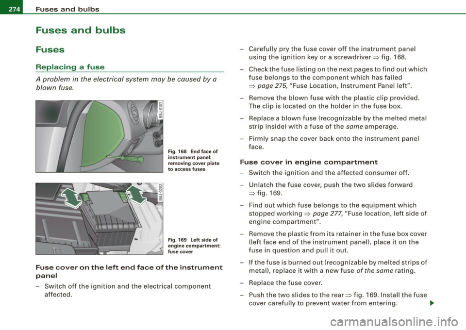
Fig . 168 End face of
instrument panel:
removing cover plate
to access fuses
Fig .
169 Left side of
engine compartment :
fuse cover
Fuse cover on the left end face of the instrument
panel
- Switch off the ignition and the electrical component
affected. - Carefully pry the fuse cover off the instrument panel
using the ignition key or a screwdriver~ fig. 168.
- Check the fuse listing on the next pages to find out which
fuse belongs to the component which has failed
~ page 275, "Fuse Locatio n, Instrume nt Panel left".
- Remove the blown fuse with the plastic clip provided.
The clip is located on the holder in the fuse box.
- Replace a blown fuse (recognizable by the melted metal
strip inside) w ith a fuse of the same amperage .
- Firmly snap the cover back onto the instrument panel
face.
Fuse cover in engine compartment
- Switch the ignition and the affected consumer off.
- Unlatch the fuse cover, push the two slides forward
~ fig. 169.
- Find out which fuse belongs to the equipment which
stopped working~ page 277, "Fuse location, left side of
engine compartment".
- Remove the plastic from its reta iner in the fuse box cover
(left face end of the instrument panel), place it on the
fuse in question and pull it out.
- If the fuse is burned out (recognizable by melted strips of
metal), replace it with a new fuse of the same rating.
- Replace the fuse cover.
- Push the two slides to the rear~ fig. 169. Install the fuse
cover carefully to prevent water from entering.
~
Page 277 of 316
Fuses and bulbs -
------------------
The various electrical circuits are protected by fuses. The fuses are
clustered in a centralized unit. The unit is located behind the face
panel at the end of the instrument panel.
Two spare fuses and a sticker identifying the fuses are located on
the inside of the fuse box cover.
You are well advised to keep a supply of spare fuses in your vehicle.
Fuses with the proper ampere ratings are available at your autho
rized Audi dealer.
& WARNING
Never replace a fuse with one that has a higher amperage rating .
• A fuse with a too high amperage could damage the electrical
part and cause a fire.
0 Note
• On no account should fuses be repaired (e.g. patched up with tin
foil or wire) as this may cause serious damage elsewhere in the elec
trical circuit or cause fire.
• If a fuse blows repeatedly, do not keep replacing it. Instead, have
the cause for the repeated short circuit or overload tracked and
fixed. •
Fuse Location , Instrument Panel left
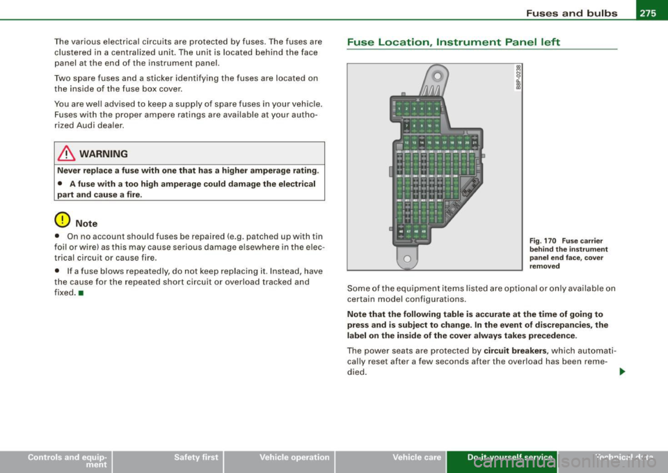
Fig . 170 Fuse carrier
behind the instrument
panelendface,cover
removed
Some of the equipment items listed are optional or only available on
certain model configurations.
Note that the following table is accurate at the time of going to
press and is subject to change. In the event of discrepancies, the
label on the inside of the cover always takes precedence.
The power seats are protected by circuit breakers, which automati
cally reset after a few seconds after the overload has been reme-
died. .,_
Vehicle care Do-it-yourself service irechnical data
Page 278 of 316

ffl.___F_ u_ s _ e_s _ a_n _ d_ b_ u_lb _ s _______________________________________________ _
Equipment No.
II Equipment
Amps I
Engine relay, fuel tank control unit, Airbag Off 16 A/C system (control unit) 10
1 light, light switch (switch illumination), diagnos-10
tic connector
17 Tire pressure monitoring system (control unit) 5
18 Not used
2 ABS, ASR, ESP, brake light switch 5
19
Not used
3 AFS headlight (left) 5 20
Not used
Oil level sensor (extended maintenance interval)
(WIVl, tire pressure monitoring system, switch
21 Fuel injectors (gasoline engine) 10
4 for Electronic Stability Program (ESP), AFS head-5 22 Wind deflector (Roadster) 30
lights (control unit), A/C system (pressure sen-23 Horn 20 llsorl, backup light switch
Automatic headlight range control, AFS head -
24 Transmission (control unit) 15
5
light (right)/ manual headlight range control, 5/10 25 Heater rear window Coupe/heated rear window 30/20
halogen headlights Roadster
Control unit for CAN data transfer (gateway),
26 Driver's side power window 30
6 electromechanical steering, automatic transmis-5 27 Passenger's side power window 30
sion shift gate
28 Not used
Acoustic Park Assist, automatic dipping interior
rear view mirror, garage door opener, heatable
29 Washer pump 15
7
windshield washer nozzles, washer pump, wind 5
30 Cigarette lighter 20
deflector relay (Roadster)
31 Starter 40
8
Haldex clutch 5 32 Steering column module 5
9
Control unit Audi magnetic ride 5 33
Instrument cluster 5
Airbag control unit 5 34 Radio navigation system, radio 15
1 1 Mass airflow sensor, crankcase heating 5/10
35
Audio amplifier 30
Door control unit (central locking driver/passen-12 10
36 Engine (control unit) 10 gerl
13 Diagnostic connector 10 37 CAN (Gateway) 5
Rain sensor, automatic transmission shift gate 5 38 Not used
15 Roof light (interior lighting) 5 39 Not
used
Page 279 of 316

_______________________________________________ F_ u_ s_ e_s _ a_ n_d _ b_u_ l_ b _s_--J _
No. Equipm ent Amps
40 Not used
41 Not used
42 Not used
43 Not us ed
44 Not use d
45 Not used
Not used
47 SDARS tuner, cell phone package, TV tune r 5
48 VDA interface
5
49 Not us ed
Fuse location , left side of engine
compartment
"' ~ M 9 -, ., m
F ig . 17 1 Illus tration o f
fu se h old er on l eft s ide
of engin e compart-
m en t: fuses (wi thout
fu se cov er)
Some of the equipment items listed a re optiona l or on ly avai lable on
ce rtain model co nfigurations .
Not e th at the foll owing t able is acc urate at th e tim e of goin g to
pr es s and i s subject to chang e. In the even t of di scr epanc ies, the
lab el on the insi de of th e cove r alwa ys takes pre ced en ce .
•
No . Equipm ent
Fuse h old er (bl ack)
1 Not used
2 Not used
3 Not used
4 Not used
5
II Anti-theft warning system (sensor), anti-theft
warning system (ho rn)
6 Headlamp washer system
7 Electric fue
l pumps (supplyl/volume control
valve
8 Windshield wipers
9 Heated seats (driver and passenger)
10 Lumbar support (driver and passenger
)
1 1 Not used
12 Ventilation b
lower
Fus e holder (brown )
1
2
3
4
5
6
7 Fuel pump (6-cylinderl
02 sensors (6-cylinderl Mass airflow sensor (6 -cy linder)
02 sensors (6-cylin derl
Relay coil relay volum e con tro l valve 14-cylin-
der)
Secondary air pump valve (6 -cylinderl , 02 sen
so rs ( 4-cylinderl
Positioning valves pre-wired engine harness
Vehicle care Do-it-yourself service
Amps
5
30
15/10 30
25 1 0
40 15
10
5
10
5
1 0
10
-
irechnical data
Page 280 of 316
.,,___F_ u_ s _ e_s _ a_n _ d_ b_ u_lb _ s _______________________________________________ _
No. Equipment Amps
8 Ignition coils (4
-cylinderl/ignition coils (6-cylin -
20/30
der)
9 Engine (control unitl 25
Water pump delayed-off 10
1 1 Feed (clutch pedal, brake pedal) 5
12
Activated charcoal filter/charge pressure con-10 trol valve (4-cylinder)
-' -
Bulbs
Replacing light bulbs
For your safety, we recommend that you have your autho
rized Audi dealer replace burned out bulbs for you.
It is becoming increasingly more and more difficult to replace
vehicle light bulbs since in many cases , other parts of the car must
first be removed before you are able to get to the bulb. This applies
especially to the light bulbs in the front of your car which you can
only reach through the engine compartment.
Sheet metal and bulb holders can have sharp edges that can cause
serious cuts, and parts must be correctly taken apart and then prop
erly put back together to help prevent breakage of parts and long
term damage from water that can enter housings that have not been properly resealed.
For your safety , we recommend that you have your authorized Audi
dealer replace any bulbs for you, since your dealer has the proper
tools, the correct bulbs and the expertise.
Gas discharge lamps (Xenon lights)*:
•
Due to the high electrical voltage, have the bulbs replaced by a qual
ified technician. Headlights with Xenon light can be identified by the
high voltage sticker .
& WARNING
Contact with high-voltage components of the electrical system
and improper replacement of gas discharge (Xenon) headlight
bulbs can cause serious personal injury and death .
• Xenon bulbs are pressurized and can explode when being
changed.
• Changing Xenon lamps requires the special training, instruc
tions and equipment .
• Only an authorized Audi dealer or other qualified workshop
should change the bulbs in gas discharge lamps.
& WARNING
There are parts with sharp edges on the openings and on the bulb holders that can cause serious cuts .
• If you are uncertain about what to do, have the work performed
by an authorized Audi dealer or other qualified workshop. Serious
personal injury may result from improperly performed work.
[ i] Tips
• If you must replace the light bulbs yourself, always remember
that the engine compartment of any vehicle is a hazardous area to
work in. Always read and heed all WARNINGS=>
page 209, "Engine
compartment"=>
/A .
• It is best to ask your authorized Audi dealer whenever you need
to change a bulb .•