AUDI TT COUPE 2009 Owner's Manual
Manufacturer: AUDI, Model Year: 2009, Model line: TT COUPE, Model: AUDI TT COUPE 2009Pages: 316, PDF Size: 71.16 MB
Page 21 of 316
battery is discharging, you should switch off any unnecessary elec
t rical consume rs (for exa mple, the air co nd itioner) .
0 Note
If the -~- warning/indicato r light (ma lfunc tion i n th e engi ne cool ing
system) in the instrument cluster shou ld illuminate:::::,
page 34, stop
t he vehicle and turn off the engine. The coo lant pump is no t work ing
- t his can cause eng ine damage! •
Applies to vehicles: with safety belt warning light
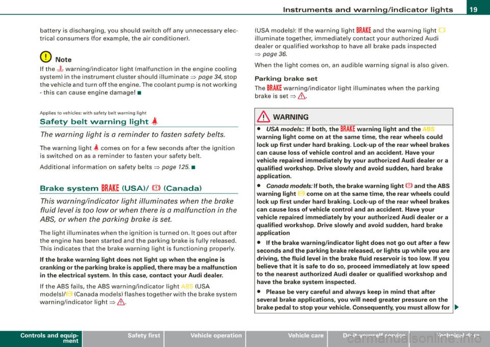
Safety belt warning light 4
The warning lig ht i s a reminder t o fasten safety belts.
T he warning light 4 comes on for a few seconds after the ignition
i s sw itched o n as a r em inder to fasten your sa fety be lt.
Additiona l information on safety belts :::::,
page 125. •
Brake system BRAKE (USA)/ (CD) (Canada)
Thi s wa rn in g/ind icator light i llumi nate s wh en the brak e
f lu id level is to o low or when t her e is a ma lfunc tion in the
ABS , or w hen the parking brake is set.
The ligh t ill umi nates whe n the igni tio n is t urned on . It goes out afte r
th e e ngine has be en started and the par king brake is fu lly released.
T his indicates that the bra ke warning light i s functioning pro perly.
If the brake warning light does not light up when the engine is
cranking or the parking brake is applied , there may be a malfunction
in the electrical system. In this case , contact your Audi dealer.
If th e ABS fai ls, the ABS warning/i ndicator light , ' (USA
m od els)/ (Ca nada mode ls) fla shes togethe r w ith the b rake sys te m
war ning/i nd icator ligh t:::::, &.
Controls and equip
ment
Instruments and warning /indi cator lights
(USA models): If the warnin g light BRAKE and the warning light
i llu min ate tog eth er, i m me dia te ly co nt ac t your author iz ed Au di
dea ler or qua lified wor kshop to have all brake pads inspected
=> page 36 .
When the li ght c omes on, a n aud ible wa rni ng sig nal i s a lso giv en.
Parking brake set
The BRAKE warnin g/indicator light i llum inates w hen the parking
brake is set:::::,& .
& WARNING
• USA models.: If both, the BRAKE warning light and the C
warning light come on at the same time , the rear wheels could
lock up first under hard braking . Lock -up of the rear wheel brakes
can cause loss of vehicle control and an accident . Have your
vehicle repaired immediately by your authorized Audi dealer or a qualified workshop . Dr ive slowly and avoid sudden , hard brake
appli cation .
• Canada models : If both, the brake warning light CCD> and the ABS
warning light ..,. come on at the same time, the rear wheels could
lock up first under hard braking . Lock -up of the rear wheel brakes
c an cause loss of vehicle control and an a ccident . Have your
vehicle repaired immediately by your authorized Audi dealer or a qualified workshop . Drive slowly and avoid sudden, hard brake
application
• If the brake warning /indicator light does not go out after a few
seconds and the parking brake released, or lights up while you are
driving, the fluid level in the brake fluid reservoir is too low . If you
believe that it is safe to do so, proceed immediately at low speed
to the nearest authorized Audi dealer or qualified workshop and
have the brake system inspected.
• Please be very careful and always keep in mind that after
several brake applications , you will need greater pressure on the
brake pedal to stop your vehi cle . Consequently , you must allow for .,_
I • •
Page 22 of 316
Instruments and warning/indicator lights
& W ARN ING (continued )
increased br aking dist ances . Trying to brake as quickly as usual
c ould lead to an a ccident. •
Anti-lock brake system , e (USA)/
(Canada)
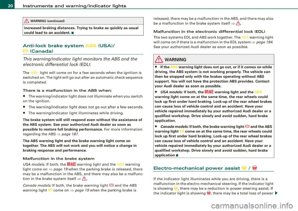
T his war ning/ indic ator ligh t moni to rs the AB S and the
elect ronic diffe ren tial lock (EDL).
The J light wil l come on for a few seconds when the ignition is
swi tc hed on. The light w ill go out aft er a n aut omat ic check seque nce
is completed.
There is a malfunction in the
ABS when :
• T he warning/indicator light does not il luminate when you switch
on the ign ition.
• T he wa rning/indicator light does not go out after a few seconds.
• The wa rnin g/ind ica tor light il luminates wh ile driv in g.
The brake system will still respond even without the assistance of
the ABS system. See your authorized Audi dealer as soon as poss ible to restore full braking performan ce . For more information
regard ing the ABS ~ page 187.
The ABS warning light and the brake warning light come on
together . The ABS will not work and you will notice a change in
braking response and performance .
Malfunction in the brake system USA models: If both, t he
BRAKE warning light and the ,,[ warning
light co me on ~ page 79when the pa rking b ra ke is r eleased, there
may be a mal function in t he ABS , and t here may also be a malfunc
tion in the brake system itself ~ & .
Canada model s: If bo th, the b rake warn ing l ig ht
(Ci) and the ABS
warning light : come on~ page 79when the parking brake is released, there may be a malfunction in the ABS, and there may also
b e a ma lfunc tio n in t he b rake system itself~ & .
Malfun ction in the electronic differential lock (EDL )
T he two sys te m s ED L and ABS w ork together . The L warning ligh t
wi ll come on if there is a malfunction in the EDL system~ page 184.
See you r au thori zed A udi deale r as so on as possible.
& WARNING
• If the "warning light does not go out , or if it comes on while
driving , the ABS system is not working properly . The vehi cle can
then be stopped only with the brakes operating without ABS support . You will not have the protection ABS provides . Contact
your Audi dealer as soon as possible.
• USA models : If both , the
BRAKE w arning light and the
warning light come on at the same time, the rear wheels could lock up first under hard braking . Lock-up of the rear wheel brakes
can cause loss of vehicle control and an accident . Have your
vehicle repaired immediately by your authorized Audi dealer or a
qualified workshop. Drive slowly and avoid sudden, hard brake
appli cation .
• Canada models: If both, the brake warning light CCI» and the ABS
warning light come on at the same time , the rear wheels could
lock up first under hard braking. Lock -up of the rear wheel brakes
c an cause loss of vehi cle control and an a ccident . Have your
vehicle repaired immediately by your authorized Audi dealer or a
qualified workshop. Drive slowly and avoid sudden , hard bra ke
application •
Electro-mechanical power assist l / @
If the indicato r light i lluminates while you a re d riv ing, t here i s a
malfunction in the e lectro -mechanica l steering . If the indicator light
is showing , there may be a reduction in powe r stee ring assist. If
t h e ind icator light is show ing® , there may be a total loss o f power
~
Page 23 of 316
steering assist. T he steering must be inspected immediately by a
qual ified workshop ~& . With the eng ine no t ru nning (e .g. when
the car is being towed) , there is also no power assist available.
& WARNING
If there is a malfunct ion , the indicator l ight for the electro-me chan
i c al power assi st illuminates . Seek profes sional as sistance. •
Controls and equip
ment
Instruments and warning /indi cator lights
I • •
Page 24 of 316
Driver inf ormation sy ste m
Driver information system
Introduction
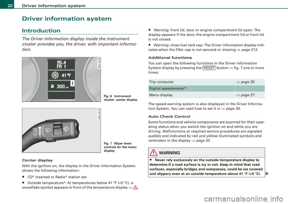
The Driver information display inside the instrument
cluster provides you, the driver, with importan t informa
tion.
C enter d ispl ay
Fi g. 6 Inst rum ent
c lu ster: cen te r d is p lay
Fi g.
7 Wipe r lever :
co ntrol s for t he m enu
di sp la y
With the ignition on, the display in th e Driver Information System
shows the fo llowing information :
• CD* inser ted or Radio * station se t
• Outside temperature*: At temperatures below 41 °F ( +5 °C), a
snowflake symbol appears in front of the tempe rature display=> &. •
Warning: front lid, door or eng ine compartment lid open: The
d isplay appears i f the door, the engine compartment lid or front lid
is not closed .
• Warning : close fuel tank cap: The Driver information display indi
cates when the filler cap is not secured or missing =>
page 213.
Additional fun ction s
You can open the following functions in the Driver Information
System display by pressing the
I RESET] button => fig. 7 one or more
times :
Trip computer =>
page25
Digital speedometer*
Menu display =>
page 27
The speed warning system is also displayed in the Driver Informa
tion System . You can read how to set it in=>
page 30.
Auto Ch eck Con tro l
Some functions and vehic le componen ts a re scanned for their oper
ating status when you switch the ignition on and while you are
driving. Malfunctions or required service procedures are signa led
audibly and indicated by red and yellow illuminated symbols and
rem inders in the display=>
page 32 .
& WARNING
• Never rel y excl usive ly on the out sid e temperature di spl ay to
determine if a ro ad surface is icy or not. Keep in m ind that road
s urface s, esp ec ially bridg es and ove rpass es, c ould be i ce c ove re d
and slippery
even a t an out sid e te mperature above 41 °F (+5 ° C ). _..
Page 25 of 316
& WARNING !continued)
• Always remember, even if the "snowflake" symbol (ice
warning) does not appear in the display, black ice could be on the road.
• Always reduce your speed and drive with special care in cold
weather conditions when the chance of encountering icy road
surfaces increases.
[ i J Tips
• On vehicles with S tronic, the reminders do not appear in the
display until you select a gear.
• On vehicles with Audi Navigation system*, the displays may
differ from their normal appearance during navigation .•
Ap plies to ve hicles: wit h gearshif t indi cato r an d ma nual t rans mission
Gearshift recommendation
This indicator con help conserve fuel.
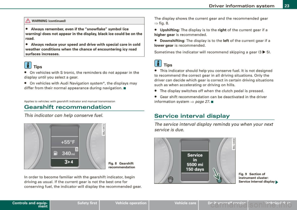
Fig. 8 Gearshift
recommendation
In order to become familiar with the gearshift indicator, begin
driving as usual. If the current gear is not the best one for
conserving fuel , the indicator will display the recommended gear.
Con tro ls and eq uip
ment
Driver information system
The display shows the current gear and the recommended gear
~ fig. 8.
• Upshifting: The display is to the right of the current gear if a
higher gear is recommended.
• Downshifting: The display is to the left of the curren t gear if a
lower gear is recommended.
Sometimes the indicator will recommend skipping a gear
(3 lllll-5).
[ i J Tips
• This indicator should help you conserve fuel. It is not designed
to recommend the correct gear in all driving situations. Only the
driver can decide which gear is correct in certain driving situations
such as when accelerating or driving on hills.
• The display switches off when the clutch pedal is pressed.
• Gear shift recommendation can be deactivated in the driver
information system
~ page 27. •
Service interval display
The service interval display reminds you when your next
service is due.
Vehicle care I I
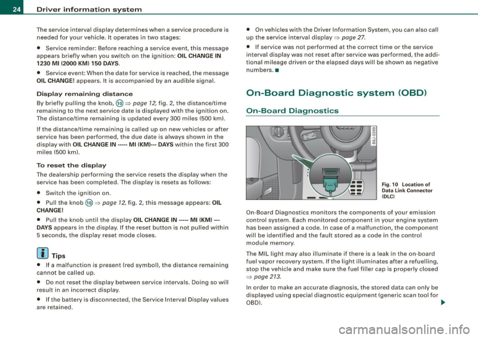
Fig. 9 Section of
instrument cluster:
Service interval display.,,_
irechnical data
Page 26 of 316
Driver information system
The service interval display determines when a service procedure is
needed for your vehicle . It operates in two stages:
• Service reminder : Before reaching a service event, this message
appears briefly when you switch on the ignition:
OIL CHANGE IN
1230 Ml (2000 KM) 150 DAYS.
• Service event: When the date for service is reached, the message
OIL CHANGE! appears. It is accompanied by an audible signal.
Display remaining distance
By briefly pulling the knob,@) ~ page 12 , fig. 2, the dis tance/time
remaining to the next service date is displayed with the ignition on.
The distance/ time remaining is updated every 300 miles (500 kml.
If the distance/time remaining is cal led up on new vehicles or after
service has been performed, the due date is always shown in the
display with
OIL CHANGE IN····· Ml (KMl··· DAYS within the first 300
miles (500 km).
To reset the displa y
The dealership performing the service resets the display when the
service has been completed . The display is resets as follows:
• Switch the ignition on.
• Pull the knob @)~
page 12 , fig. 2, this message appears : OIL
CHANGE!
• Pull the knob unti l the display OIL CHANGE IN····· Ml (KM)···
DAYS
appears in the display. If the reset button is not pulled within
5 seconds, the disp lay reset mode closes.
[ i J Tips
• If a malfunction is present (red symbol), the distance remaining
cannot be called up.
• Do not reset the display between service intervals. Doing so will
result in an incorrect display.
• If the battery is disconnected, the Service Interval Display values
are reta ined. •
On vehicles with the Driver Information System, you can also call
up the service interval display~
page 27.
• If service was not performed at the correct time or the service
interval display was not reset after service was performed, the addi
tional mileage driven or the elapsed days will be shown as negative
numbers. •
On-Board Diagnostic system (OBD)
On-Board Diagnostics
Fig. 10 Locat ion of
Data Link Connector
( DLC )
On-Board Diagnostics monitors the components of your emission
control system . Each monitored component in your engine system
has been assigned a code. In case of a malfunction, the component
wi ll be identified and the fault stored as a code in the control
module memory.
The MIL light may also illuminate if there is a leak in the on -board
fuel vapor recovery system. If the light ill uminates after a refuelling,
stop the vehicle and make sure the fuel fi ller cap is properly closed
~ page 213.
In order to make an accurate diagnosis, the stored data can only be
displayed using special diagnostic equipment (generic scan tool for
OBD) . ...
Page 27 of 316
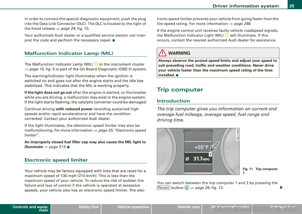
In order to connect the special diagnostic equipment, push the plug
into the Data Link Connector (DLC). The DLC is located to the right of
the hood release =>
page 24, fig. 10.
Your authorized Audi dealer or a qualified service station can inter
pret the code and perform the necessary repair. •
Malfunction Indicator Lamp (MIL)
The Malfunction Indicator Lamp (MIU in the instrument cluster
=>
page 15, fig. 5 is part of the On -Board Diagnostic (OBD II) system.
The warning/indicator light illuminates when the ignition is
switched on and goes out after the engine starts and the idle has
stabilized. This indicates that the MIL is working properly.
If the light does not go out after the engine is started, or illuminates
while you are driving, a malfunction may exist in the engine system.
If the light starts flashing, the catalytic converter could be damaged .
Continue driving
with reduced power (avoiding sustained high
speeds and/or rapid accelerations) and have the condition
corrected. Contact your authorized Audi dealer .
If the light illuminates, the electronic speed limiter may also be
malfunctioning . For more information=>
page 25, "Electronic speed
limiter".
An improperly closed fuel filler cap may also cause the MIL light to
illuminate =>
page 213. •
Electronic speed limiter
Your vehicle may be factory equipped with tires that are rated for a
maximum speed of 130 mph (210 km/h). This is less than the
maximum speed of your vehicle . To reduce the risk of sudden tire
failure and loss of control if the vehicle is operated at excessive
speeds, your vehicle also has an electronic speed limiter. The elec-
Controls and equip
ment
Driver information system
tronic speed limiter prevents your vehicle from going faster than the
tire speed rating. For more information =>
page 246.
If the engine control unit receives faulty vehicle road speed signals,
the Malfunction Indicator Light (MIU•"" will illuminate. If this
occurs, contact the nearest authorized Audi dealer for assistance.
& WARNING
Always observe the posted speed limits and adjust your speed to
suit prevailing road, traffic and weather conditions. Never drive
your vehicle faster than the maximum speed rating of the tires installed. •
Trip computer
Introduction
The trip computer gives you information on current and
average fuel mileage, average speed, fuel range and
driving time.
Fig . 11 Trip computer
1
You can switch between the trip computer 1 and 2 by pressing the
! Reset! button®=>
page 26, fig. 12. .,,_
I • •
Page 28 of 316
Driver inf ormation sy ste m
You can tell which memory level is currently active by the number in
the display =>
page 25, fig. 11. The data from the single -trip memory
(memory level 1 l is being displayed if a
1 appears in the disp lay. If a
2 is shown, then the data from the total -trip memory is being
displayed (memory leve l 2l.
S in gle-trip m emor y (Trip c ompu ter 1 )
The single-trip memory stores the trip information from the time the
ignition is turned on until it is turned off . If the trip is con tinued
w ithi n 2 hour s from the time the ignition was turned off, the new
data will be included in the calculation of the current trip informa
tion. If the trip is interrupted for
more than 2 ho ur s the memory is
reset automatica lly.
T ot al-tr ip m em ory ( Trip co mpu te r 2)
Unlike the single -trip memory, the total -trip memory is no t reset
automatically . This permits you to evaluate your driving data for the
entire period between manua l resets.
F u el ra nge
The estimated cruising range in miles (km) appears in the display.
The display changes in increments of 6 miles (10 km) .
Avera ge fuel mil eage
The average fuel economy in MPG 0/100 km) since you last cleared
the memory appears in this display.
C ur rent f uel mileage
The instantaneous fuel consumption in mi les per ga llon (1/100 km)
is shown in this display. When the vehicle is stationary, the most
recent fuel consumption is displayed.
A ve ra g e sp eed
The average speed in mph (km/h) s ince the last time the display was
reset appears in the display.
El ap se d tim e
The length of time that you have been driving since you last rese t
the memory appears in this disp lay. The maximum time period that
can be recorded i s 999 hours and 59 minutes .
Distance
The elapsed distance since the last t ime the memory was cleared
appears in the display . The maximum distance that can be recorded
is 9,999 .9 mi les (9,999.9 kilometers).
[ i ] Tips
All stored values will be lost if the vehicle battery is disconnected .•
Op eration
The trip computer is controlled by two switches on the
windshield wiper lever.
Sel ecting th e trip comput er
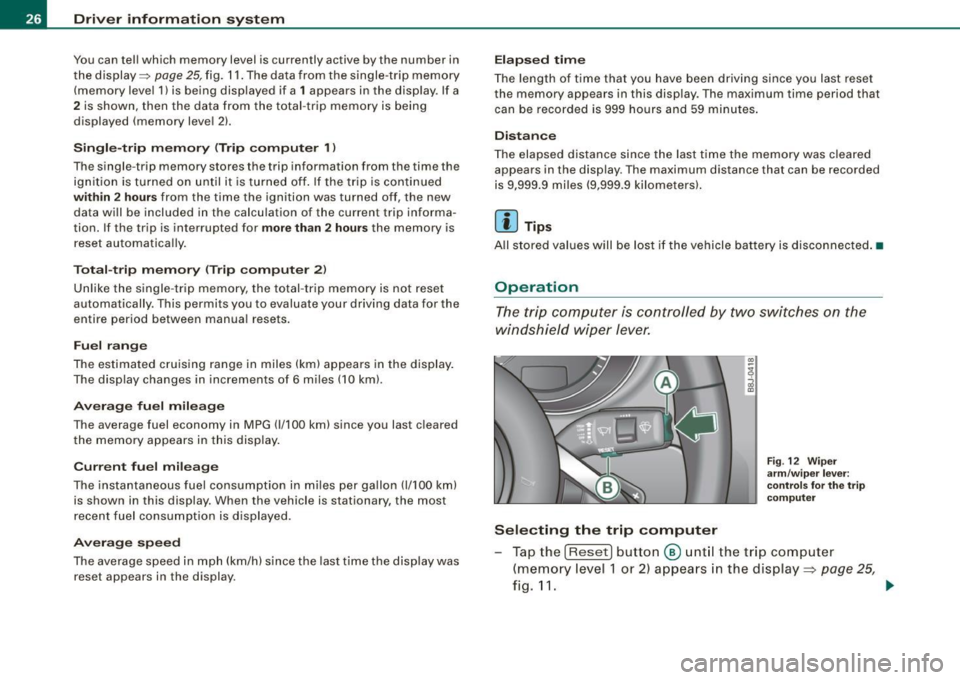
Fig . 12 Wip er
a rm /w ip er leve r:
co ntrols fo r the t rip
co mput er
Tap the [Reset) button @ unt il the trip computer
(memory level 1 or 2) appears in the display =:>
page 25,
fig.11. _.
Page 29 of 316

Sele cting the fun ctions
- Push in the uppe r (lower) protrusion on the function
se lector switch
@ =>page 26, fig. 12. The functions for
the trip compu ter are d isp layed in succession on the
respective memory levels.
R ese ttin g the function to z ero
- Push the [Reset ] button ® for at least two seconds .
You can reset the fo llowing values to zero using the [R eset] button:
• driving time
• distance
• average fuel mileage
• average speed
The trip computer only opera tes when the ignition is on . When you
turn on the ignit ion, the function that was in use when you last
turned the ignition off will be displayed.
[ i ] T ip s
• You can also set the va lues for the functions to zero in the menu
display (R es et) ~
page 27 .
• All stored values wil l be lost if the vehic le battery is
disconnected .•
Con tro ls and eq uip
ment
Menu display
Introduction Dri
ver in form ati on syst em
Fig . 13 W ip er leve r:
Co ntrols for the men u
di sp la y
Fig . 14 Di spl ay: Star t
menu
Some functions in your vehicle can be set, activated, and controlled
by Men us (e.g. Acoustic park assist*) . With these menus you can
also select the informa tion shown in the driver information system ,
which operates only with the ignition switched on . Operation is
controlled by the
I Res et I button and the rocker switch on the wiper
lever~fig .13 . .,_.
Vehicle care
I I Technical data
Page 30 of 316
Driver inf ormation sy ste m
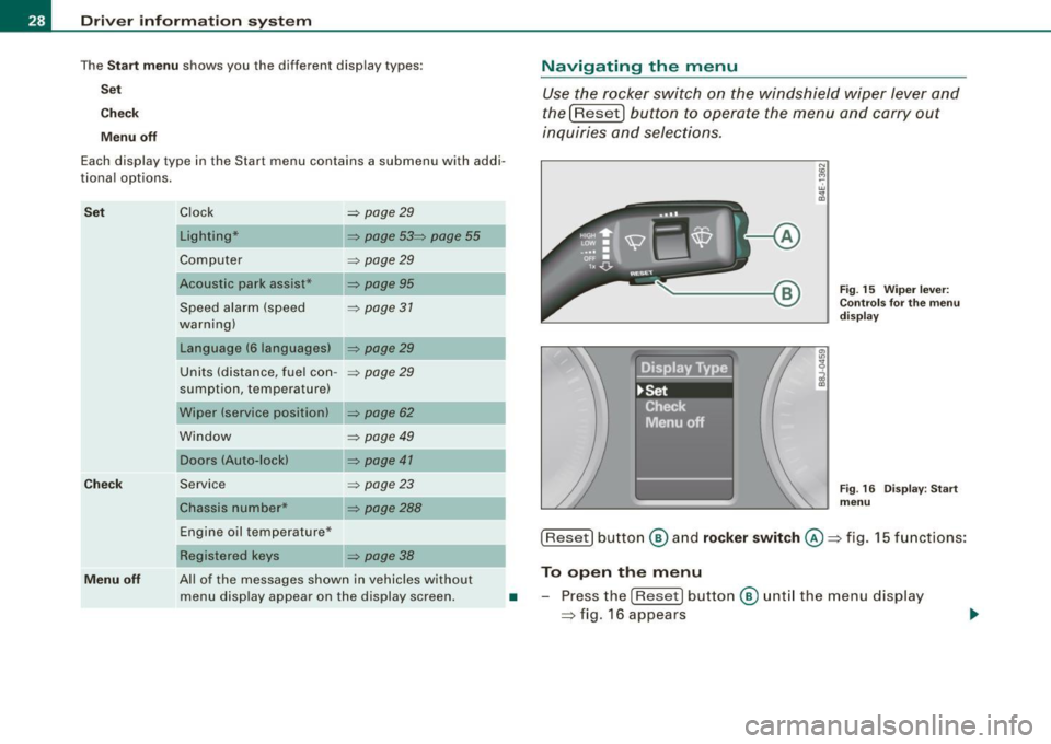
The Sta rt m enu shows you the different disp lay types:
Se t
Check
M enu off
Each display type in the Start menu contains a submenu with addi
tional options.
S et
Ch eck
Clock ~ page29
Lighting* ~ page 53~ page 55
Computer ~ page29
Acoustic park assist* ~ page95
Speed alarm (speed ~ page 37
warning)
Language (6 languages)
~ page29
Units (distance, fuel con -~ page29
sumption, temperature)
Wiper (service position)
~ page 62
Window ~ page 49
Doors (Auto-lock) ~ page 41
Service
Chassis number* ~ page23
~ page288
Navigating the menu
Use the rocker switch on the windshield wiper lever and
the[Reset) button to operate the menu and carry out
inquiries and selec tions.
-A
N
"' cc
Fig . 15 Wiper leve r:
Con trols fo r th e m enu
d is pla y
Fig . 16 Disp lay: Start
menu
Engine oil temperature* ___ __, [Reset] button ® an d rock er swit ch @ => fig. 15 functions:
Menu off
Registered keys ~ page 38
All of the messages shown in vehicles without
menu display appear on the display screen. To open the menu
• -Press the [Reset ) button ® unt il the menu display
=> fig. 16 appears