battery AUDI TT COUPE 2016 Owners Manual
[x] Cancel search | Manufacturer: AUDI, Model Year: 2016, Model line: TT COUPE, Model: AUDI TT COUPE 2016Pages: 322, PDF Size: 52.86 MB
Page 6 of 322
Downloaded from www.Manualslib.com manuals search engine Table of contents
Side airbags . . . . . . . . . . . . . . . . . . . . . . . . 206
Side cu rtain airbags . . . . . . . . . . . . . . . . . . 209
Child safety . . . . . . . . . . . . . . . . . . . . . . 212
I
mportant information . . . . . . . . . . . . . . . 212
Child seats . . . . . . . . . . . . . . . . . . . . . . . . . 218
Secur ing child seats . . . . . . . . . . . . . . . . . . 223
LATCH system (Lower anchorages and
tethers
for children) . . . . . . . . . . . . . . . . . 226
Add it io nal info rmation . . . . . . . . . . . . . . . 230
Maintenance and Care ........... 231
Checking and Filling . . . . . . . . . . . . . 231
Fuel
..... .. .. ................... .. . 23 1
Refueling . . . . . . . . . . . . . . . . . . . . . . . . . . 23 2
Cat alytic conver te r . . . . . . . . . . . . . . . . . . . 235
E ng ine com partment . . . . . . . . . . . . . . . . . 236
Eng ine oil . . . . . . . . . . . . . . . . . . . . . . . . . . 239
Cooling system . . . . . . . . . . . . . . . . . . . . . . 242
Brake fluid . . . . . . . . . . . . . . . . . . . . . . . . . 244
Battery . . . . . . . . . . . . . . . . . . . . . . . . . . . . 245
W indshield washer system . . . . . . . . . . . . 248
Service in terval display . . . . . . . . . . . . . . . 249
Wheels . .. .. .. ................... . 250
Wheels and Tires . . . . . . . . . . . . . . . . . . . . 250
Tire pressu re monitoring system 267
Care and cleaning . . . . . . . . . . . . . . . . 270
General information . . . . . . . . . . . . . . . . . 270
Car washes . . . . . . . . . . . . . . . . . . . . . . . . . 270
C leaning and care information ...... .. . 271
Placing your veh icle out of service 274
Do It Yourself . . . . . . . . . . . . . . . . . . . . 275
Emergency ass istance . . . . . . . . . . . 275
General information . . . . . . . . . . . . . . . . . 275
Equipment ... .. ................... . 275
Tire mobility kit . . . . . . . . . . . . . . . . . . . . . 275
R ep lacing wheels . . . . . . . . . . . . . . . . . . . . 277
Spare tire . . . . . . . . . . . . . . . . . . . . . . . . . . 283
4
Fus e s and bulbs . . . . . . . . . . . . . . . . . . 285
E lectrica l fuses . . . . . . . . . . . . . . . . . . . . . . 28S
Bulbs. . . . . . . . . . . . . . . . . . . . . . . . . . . . . . 287
Emergency situations . . . . . . . . . . . . 288
Genera l . . . . . . . . . . . . . . . . . . . . . . . . . . . . 288
Starting by push ing o r towing . . . . . . . . . . 288
Starting with jumper cables . . . . . . . . . . . 288
Use o f jumper cables . . . . . . . . . . . . . . . . . 289
T ow ing with a tow t ruck . . . . . . . . . . . . . . 290
Raising the vehicle . . . . . . . . . . . . . . . . . . . 292
Consumer information and
technical data . . . . . . . . . . . . . . . . . . . . 294
Consumer information . . . . . . . . . . 294
Warranty coverages . . . . . . . . . . . . . . . . . . 29 4
Operat ing you r vehicle outs ide th e U .S.A.
or Canada . . . . . . . . . . . . . . . . . . . . . . . . . . 294
Audi Service Repair Manuals and
Literature . . . . . . . . . . . . . . . . . . . . . . . . . . 294
Maintenance. . . . . . . . . . . . . . . . . . . . . . . . 294
Accessor ies and technical changes . . . . . . 296
Technical data . . . . . . . . . . . . . . . . . . . . 298
Vehicle identification . . . . . . . . . . . . . . . . . 298
Weights . . . . . . . . . . . . . . . . . . . . . . . . . . . 298
Dimens ions . . . . . . . . . . . . . . . . . . . . . . . . . 299
Capacities . . . . . . . . . . . . . . . . . . . . . . . . . . 299
Gasoline eng ines 300
Index ........ ...... ............... 301
Page 12 of 322

Downloaded from www.Manualslib.com manuals search engine Instruments and indicator lights
Electronic Stabilization Control (ESC)
../¢page 14
Electronic Stabilization Control (ESC)
../¢page 14
USA models: anti-lock braking sys
tem (ABS)../
¢page 14
Canada mod els : anti- lock braking
system
(ABS) ../
¢page 14
• Brake
p
ads
¢page 15
10
Elect romechan ical park ing bra ke
¢ page 12
Tire pressure monitoring system../
¢page268
Tire pressure monitoring system
¢page268
Engi ne control
¢ page 15
System indicator light (MIL)
¢page 15
Engine speed limitation
¢page 15
Engine oil level
¢ page 15
Engine oil senso r
¢page 16
Battery charge
¢page 13
Tank system
¢page 16
Was her fluid level
¢page 16
W indshield wipers
¢ page 16
Remote control key
¢page 60
Battery in remote control key
¢page27
Bulb failure indicator*
¢ page 16
Head light range control system
¢page 16
Adaptive light*
¢ page 17
Light/rain sensor *
¢page 17
Transmission
¢ page 70
Steering lock
¢page 13
Engine start system
¢ page 14
Central indicator light
¢page 14
Electromechanical steering../
¢ page 90
Dampe r control*
¢ page 17
Rear spoiler
¢page 91
Speed warning system*
¢page 72
Other indicator lights
•
~ Turn signals
~ !!11!.i ¢page 17
CRUISE
USA models: cruise contro l system*
¢ page 72
Canada models: cruise contro l sys
tem*
¢ page 72
Active lane assist*
¢ page 75
Convenie nce key
¢page 60
Electromechanical parking brake
¢ page 12
Active lane assist*
¢page 75
Audi side ass ist*
¢page 79
• Transmission
.W¢page70
Page 15 of 322

Downloaded from www.Manualslib.com manuals search engine ...... N
G'. CX)
..... ID IJ' ..... ID .....
CD Note
Do not continue driving if the. indicator
light turns on -this increases the risk of en
gine damage.
~ Engine oil pressure
• Turn off engine. Oil pressure too low
Stop the engine and do not continue driving.
Check the engine oil level~ page 240.
-If the engine oil level is too low, add engine oil
~page 240. Only continue driving once the in
dicator
light turns off.
-
If the engine oil level is correct and the indica
tor light still blinks, turn the eng ine off and do
not continue driving. See an authorized Audi
dealer or authorized Audi Service Facility for as
sistance.
Tips
The oil pressure warning is not an oil level in
dicator. Always check
the oil level regularly.
t:3 Alternator/battery
• Electric system: malfunction! Battery is not
being charged
There is a malfunction in the alternator or the ve
hicle electrical system.
Drive
to an authorized Audi dealer or author ized
Audi Service Facility immediately. Turn off all un
n
ecessar y electrica l equipment because it will
drain
the battery. See your authorized Audi deal
er or authorized Audi Service Facility if the bat
tery charge level is too low.
f•l Electrical system: low battery charge. Please
turn on ignition
The starting ability may be impaired.
If this message turns off after a little while, the
battery charged enough while driving.
If the message does not turn off, have and au
thorized Audi
dealer or authorized Audi Service
Facility repair the malfunction .
Instruments and indicator lights
~Engine stop while driving
• Engine stopped: no power steering or brake
servo possible
There is a malfunction in the engine or in the fuel
supply system.
More force
is needed to steer and brake the mov
ing vehicle
when the engine is stopped. If the ve
hicle
is rolling, try to bring it to a stop off to the
side from moving traffic. See an authorized Audi
dealer or authorized Audi Service Facility for as
sistance.
.& WARNING r-= ____,
If the engine stops while driving, you will
need
to use more f orce to brake the vehicle.
This i
ncreases th e risk of an acc ident. There
will still
be power steering if the ignition is
switched on while the vehicle is rolling and
there is sufficient battery charge. Otherwise,
you
must use greater force when steering.
~ Front safety belt
The . indicator light stays on until the driver's
and front passenger's• safety belts are fastened .
Above a certain
speed, there will also be a warn
ing
tone.
© Tips
For additional information on safety belts, re
fer
to~ page 180.
@-e Steering lock
• Steering: malfunction! Please stop vehicle
There is a malfunction
in the electronic steering
lock. You cannot turn the ignition on.
Do not tow your vehicle because it cannot be
steered. See an authorized Audi dealer or author
ized Audi Service Facility for assistance.
ml Steering lock: malfunction! Please contact
Service
There
is a malfunction in the electronic steering
lock . ~
13
Page 26 of 322
Downloaded from www.Manualslib.com manuals search engine Driver information system
-Recuperation : electrical energy can be stored in
the battery when the vehicle is coasting or driv
i ng
downhill. The bar will move toward t:::l.
@ Tips
- The da te, time of day and time and date for
mat can be set in the Infotainment system.
- I f the vehicle battery is disconnected, all
memory va lues are erased.
24
Page 29 of 322
Downloaded from www.Manualslib.com manuals search engine ..... N
G: CX)
.....
"' U"I
LED and batteries in the remote control key
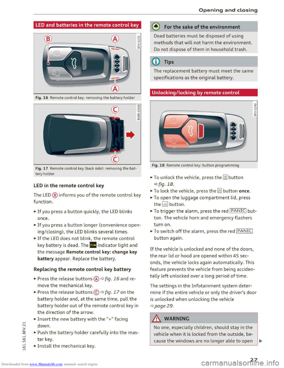
Fig. 16 Rem ote contro l key: rem ov ing the battery hol der
Fig. 17 Remote control key (back side ): remov ing the ba t
tery ho lder
LED in the remote control key
The LE D @ info rms you of the remote control key
function.
•If you press a button quick ly, the LED blinks
once .
• If you press a button longer (convenience open
ing/ closing), the LED blinks several times.
•If the LED does not blink, the remote control
key battery is dead . The Ill indicator light and
the message Remote control key: change key
battery appear. Replace the battery.
Replacing the remote control key battery
• Press the release buttons@ ¢ fig. 16 and re
move the mechanical key.
.. Press the release buttons© ¢ fig. 17 on the
battery holder and, at the same time, pull the
battery holder out of the remote contro l key in
the direction of the arrow .
.. Insert the new battery with the"+ " facing
down .
.. Push the battery holder carefully into the mas
ter key.
~ •Install the mechanical key . .....
Opening and closing
@) For the sake of the environment
Dead batteries must be disposed of using
methods that will not harm the environment.
Do not dispose of them in household trash.
@Tips
The replacement battery must meet the same
specificat ions as th e origina l battery.
Unlocking/locking by remote control
Fig. 18 Remote contro l key : button programming
.. To unlock the vehicle , press the Im button
¢ fig. 18.
.. To lock the vehicle, press the~ button once.
.. To open the luggage compartment lid, press
the~ button .
.. To trigger the alarm, press the red I PANIC I but
ton. The vehicle horn and emergency flashers
turn on.
•To switch off the alarm, press the red I PANIC I
button again .
If the vehicle is unlocked and none of the doors,
the rear lid or hood are opened within 45 sec
onds,
the veh icle locks again automatically. This
f
eature prevents the vehicle from being acciden
tally
left un locked over a long period of time.
T
he setti ngs in the Infota inment system deter
mine if the entire vehicle or only the driver's door
is un locked when un locking the vehicle
¢page 29.
A WARNING
--1
No one, especially children, should stay in the
vehicle when it is locked from the outside, be
cause the windows are no longer able to open
27
Page 30 of 322
Downloaded from www.Manualslib.com manuals search engine Opening and closing
from the inside 9 page 30. Locke d doors
ma ke it more difficu lt for emergency workers
to
get into the vehicle, which puts lives at
risk .
(D Tips
-Only use the remote control key when you
are within view
of the vehicle.
-
Do not use the remote control when you are
i nside
the vehicle. Otherwise, you could un
intentionally lock the vehicle. If you then
tried
to start the eng ine or open a door, the
alarm would be triggered. If this happens,
press
the u nlock button 0 .
- The selector lever must be in the P position
on veh icles with a convenience
key*. Other
wise the ve hicle will not be able to lock .
-
Only use the panic functio n in an emergen
cy.
Locking and unlocking with the
convenience key
Appl ies to: vehi cles with conve nience key
The doors and luggage compartment lid can be
unlocked/locked without using
the remote con
trol key.
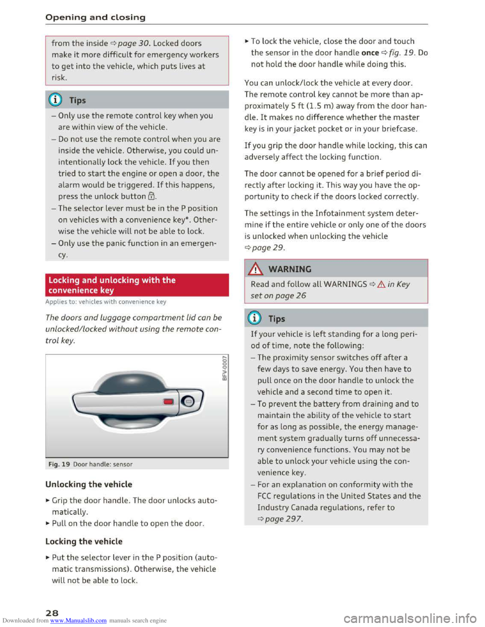
Fig. 19 Door handle: sensor
Unloc king the vehicle
... Grip the door handle. The door unlocks auto
matically.
.,. Pull on the door handle to open the door.
Locking the ve hicle
... Put the selector lever in the P position (auto
matic transmissions) . Otherwise,
the vehicle
will not be able to lock .
28
... To lock the vehicle, close the door and touch
the sensor in the door handle once 9 fig. 19. Do
not hold the door handle while doing this.
You can unlock/ lock th e veh icle at every door.
The remote control
key cannot be more than ap
proximately 5
ft (1.5 m) away from the door han
dle.
It makes no difference whether the master
key is in your jacket pocket or in your briefcase.
If you grip the door handle
while locking, this can
adverse ly affect
the locking function.
The door canno t be opened for a b rief period d
i
rectly after locking it. This way you have the op
po rtunity to check if
the doors locked correct ly .
The
setti ngs in the I n fotainment system deter
mine if the entire veh icle or o n
ly one of the doors
i s
unl ocked when unlocking th e vehicle
9page29.
A WARNING
Read and follow all WARNINGS 9 & in Key
set on page 26
(!) Tips
If your vehicle is left standing for a lo ng peri
od
of t ime, note the following:
- T he proxim ity sensor switches off a
fter a
few days to save ener
gy. You then have to
pull once on
the door handle to unlock the
vehicle and a second time to open it.
- To prevent
the battery from draining and to
maintain the ability of the vehicle to start
for as long as poss ible, the energy manage
ment system gradually turns off unnecessa
ry convenience functions . You may not be
able
to unlock your vehicle using the con
venience key.
-
For an explanat io n on conform ity with the
FCC reg ulations in the United States and the
Industry Canada regulatio ns, refer to
9page 297 .
-
Page 35 of 322

Downloaded from www.Manualslib.com manuals search engine ..... N
G: CX)
.....
"' U"I
.....
"' .....
-For security reasons, the windows can only
be
opened and closed with the remote con
trol key at a maximum distance of approxi
mately 6 ft (2 m) away from the vehicle.
When pressing the[@ button, always watch
the windows while they are closing so that
no one is pinched in the window. The closing
process will
stop immediately when the~
button is released.
Correcting power window malfunctions
After disconnecting the vehicle battery, the one
touch up
and down feature must be activated
again.
~ Pull the power window switch until the window
is completely ra ised.
~Release the switch and pull it again for at least
one second.
Garage door opener
(Homelink)
Description
Applies to: vehicles with garage door opener (Homelink}
Fig.
27 Garage door opener: examp les of usage for diffe r
ent system s
W ith the garage door opener (Homelink), you
can activate
systems such as the garage doors,
security
systems or house lights from inside your
vehicle. Up to three remote control functions can
be
programmed to the three buttons that are in
tegrated in the control unit above the rearview
mirror .
T o
be able to operate systems using the garage
door opener, the buttons in the control unit must
first be programmed .
Opening and closing
A WARNING
f=
When operating or programming the garage
door opener, make sure that no people or ob
jects are in the area immediately surrounding
the system. People can be inju red o r property
can be damaged if struck when closing.
@ Tips
-For security reasons, we recommend that
you clear the programmed buttons before
selling the vehicle.
- For
further information regarding Home
Link,
refer to www.homelink.com .
-For the Declaration of Conformity with the
prov is ions from the FCC in the United States
and Industry Canada, refer to~ page 297.
Operation
Applies to: vehicles with garage door opener (Home link)
Fig .
28 Contro l panel above the interio r rearv iew mirro r
Requirement: the button in the control panel
must be programmed~ page 34 and the vehi
cle
must be located within range of the system,
suc h
as the garage door.
~ Press the button to open the garage door. The
green LED@ blinks or turns on.
~ Press the button again to close the garage
door.
(j) Tips
To open or close the garage door, do not
press the button longer than 20 seconds or
the garage door opener will switch to pro
gramming mode.
33
Page 38 of 322
Downloaded from www.Manualslib.com manuals search engine Lights and Vision
Lights and Vision
Exterior Lighting
Switching lights on and off
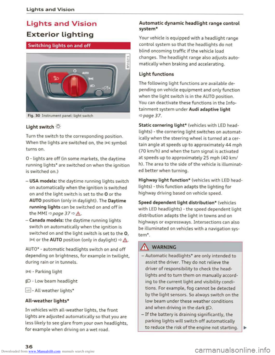
Fig. 30 Instrument panel: light switch
Light switch ·'t/;
Turn the switch to the corresponding position.
When
the lights are switched on, the :oo: symbol
turns on.
0 -lights are off (in some markets, the daytime
running
lights* are switched on when the ignition
is switched on.)
-USA models: the daytime running lights sw itch
on automatica
lly when the ignition is sw itched
on and
the light switch is set to the 0 or the
AUTO position (only in daylight). The Daytime
running lights
can be switched on and off in
the MMI ~page 37 Q &.
-Canada models: the daytime running lights
switch on automatically when the ignition is
switched on and the light switch is set to the 0,
:oo: or the AUTO position (only in daylight) QA .
AUTO* -automatic headlights switch on and off
depending on brightness, for example in twilight,
during rain
or in tunnels.
:oo: -Parking light
~D -Low beam headlight
~ -All weather lights*
All-weather lights*
In vehicles with all-weather lights, the front
lights are adjusted automatically so that you are
less likely
to see glare from your own headlights,
for example when driving on a wet road.
36
Automatic dynamic headlight range control
system*
Your vehicle is equipped with a headlight range
control system
so that the headlights do not
blind oncoming traffic if the vehicle load
changes. The headlight range also
adjusts auto
matically when braking and accelerating .
Light functions
The following light functions are available de
pending on vehicle equipment and only function
when the
light switch is in the AUTO position.
You can deactivate these functions in the Info
tainment system under Audi adaptive light
Qpage 37.
Static cornering light* (vehicles with LED head
lights) -the cornering light switches on automat
ically when the steeri ng wheel is turned at acer
tain angle at speeds up to approximately 44 mph
(70 km/h) and when the turn signal is activated
at speeds up to approxim ately 25 mph (40 km/
h). The area
to the side of the vehicle is illuminat
ed better when turning.
Highway light function* (vehicles with LED head
lights) -this function adapts the lighting for
highwa y driving based on vehicle speed.
Speed dependent light distribution* (vehicles
with LED headlights) -the speed dependent light
distribution adapts the light in towns and on
highways
or expressways. Intersections can also
be illuminated on vehicles
with a navigation sys
tem*.
A WARNING
- Automatic headlights * are only intended to
assist the driver. They do not reliev e the
driver
of responsibility to check the head
lights and to turn them on manually accord
ing to the current ligh t and visibility condi
tions. For example, fog cannot be detected
by
the light sensors . So always switch on the
low beam under these weather conditions
and when
driving in the dark ~D.
-If the battery is dra ining significantly, the
parking lights will switch off automatically
to reduce the risk of the engine not starting . ..,..
Page 49 of 322

Downloaded from www.Manualslib.com manuals search engine ..... N
G: CX)
.....
"' U"I
.....
"' .....
Ashtray
Applies to: veh icles with ashtray
Fig. 46 Center armrest folded up: asht ray
The ashtray is p laced in the center console under
the center armrest. Lift up the cover to open. In
sert the ashtray securely back into t h e ho lder af
ter eve ry removal (emptying).
A WARNING
Never use the ashtray to hold paper, because
this inc reases the risk of a fire.
Cigarette lighter and
socket
Fig. 47 Center armrest folded up: ci9arette li9hter
The cigarette lighter or socket only functions
when the ignition is sw itched on.
Using the cigarette lighter
.,. Fold the center armrest up to reach the ciga
rette lighte r, if necessa ry .
.. Press the cigarette lighter in .
.. Remove the c igarette lighter when it pops out .
Seats and storage
Using the socket
.,. Fold th e center armres t up to rea ch the so cket,
if necessary .
.. Remove the cigarette lighter, if necessary .
.. Insert the plug of the e lectrica l device into the
socket.
T
he cigarette lighter has a standard 12 Volt sock
et that electrica l accessories can be connected to.
The power consumption at the outlet must not
exceed 100 watts.
A WARNING
r-=-
Use care when us ing the cigarette lighter. In-
attentive or unsupervised use of the cigarette
lighter can cause burns.
CD Note
-To reduce the risk of damage to the sockets,
only use plugs that fit correctly.
- The
cigarette lighter socket should only be
used as a power source for electrical acces
sories for a short period of time. The sock
ets* in th e veh icle should be used for longer
use
of power supply .
©Tips
-The vehicle battery drains when accessories
are turned on but the engine is off.
- The vehicle
battery must not be charged us
ing a commercially available small charging
device, which is co nnected
to the cigarette
lighter or socket.
47
Page 56 of 322
Downloaded from www.Manualslib.com manuals search engine Warm and cold
-Switching manua l recirculation mode on and
off: press ld<>I
-A utomatic* recircu lation mode: auto rec ircula
tion needs to be activated in the Infotainment
system. Select in the Infotainment system:
IMENUI button> Vehicle > left control button
>Vehicle settings > Air condit ioning > Auto re
circul ation . The air quality sensor that is de
s i
gned for diesel and gasoline exhaust auto
matically switches the recircu lation mode on or
off depending on the level of pollutant s in the
o utside air.
In recirculation mode, the a ir inside the vehicle is
circulated
and filtered. This prevents the u nfil
tered a ir outside the vehicle from entering the
ve hicl e interio r. We recommend switching recir
cula tion mode on when driv ing thr o ugh a tunnel
or when sitting in traffic<::>.&..
Recirc ulation mode is switched off by pressing
the 1- 1 button o r IAUTOI orlw MAXI.
I@ M AX I Switching defrost on and off
The windshield and side windows are defrosted
or cleared of condensation as quickly as possible.
The
optimum amoun t of a ir flows mainly out of
the vents under the windshield . Rec irculatio n
mode switches off. The temperature is contr olled
automatically.
The IAUTOI button switches the defroster off.
IO!il R EARI Switching the rear window defogger
on and
off
If the rear window defogger is activated when
the ign ition is switched on, the battery manage
ment determ ines based on the ba ttery c harge if
it is possible t o t urn on . Othe rwise, the rear win
dow defogger functions with the engine run ning
and switches off automatically after approxi
mately 10 -20 mi nutes, depending on the out
side temperature.
To preven t
the rear window defogger from
switching off automatically, press and hold the
lliill REARI button for more than 2 seconds. This re
mains stored up to approximately lS minutes af
ter turning off the ignition.
54
A WARNING
You should not use the recirc ulation mode for
an extended period since no fresh air i s drawn
in . With the air-conditioning switched off, the
windows can fog up, which inc reases the risk
of an accident.
Adjusting
the air vents
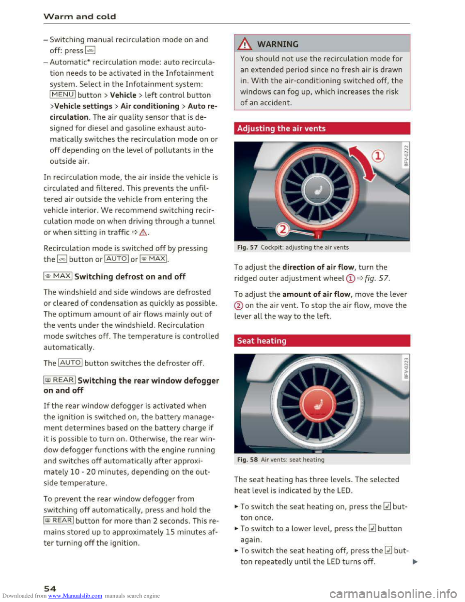
Fig. 57 Cockpit: adj ust ing the air vents
To adjust the direction of air flow , turn the
ridged outer adjustment wheel©<::> fig. 57.
To adjust the amount of air flow, move the lever
@on the air vent. To stop the air flow, move the
lever all the way to the left.
Seat heating
Fig. 58 Air vents: seat heating
The seat heati ng has three levels. The selected
heat level is indicated by the LED.
... To switch the seat heating on, press the~ but
ton once.
... To switch to a lower level, press the~ button
again.
.,. To switch the seat heating off, press the~ but-
ton repeatedly until the LED t u rn s off. .,..