AUDI TT ROADSTER 2015 Owners Manual
Manufacturer: AUDI, Model Year: 2015, Model line: TT ROADSTER, Model: AUDI TT ROADSTER 2015Pages: 244, PDF Size: 60.74 MB
Page 211 of 244
.. Close your grip around the end of the
wrench handle for maximum torque and
turn the wheel bolts
c ounter-clockwis e
about one single turn in the direct ion of ar
row
r:> fig . 154.
Tightening
.. Fit the wheel bol t wrench over the wheel
bolt and push it down as far as it will go .
.. Close your grip around the
end of the
wrenc h handle for maximum torque and
turn each wheel bolt
cl ock wis e unt il it sits
t ight .
A WARNING
-Us ing fo rce without control to speed the
wheel change up can cause the veh icle to
slip off the jack and ca use se rious pe r
sonal in juries.
-Do not loosen the wheel bolts more than
one turn
before you ra ise the veh icle with
the jack. -Risk of inj ury!
(1) Tips
- N ever t ry and use the hexagona l socket
i n the handle of the screwdriver to loos
en or tighte n the wheel bolts .
- If a whee l bolt sits very t ight, you may
find i t easie r to loosen by carefully p ush
i ng down on the end of the whee l bolt
wrench with
one foot only . As you do,
ho ld on to the car to keep yourse lf stable
and ta ke care not to slip .
Raising the vehicle
The vehicle must be lifted with the jack first
before the wheel can be removed .
..
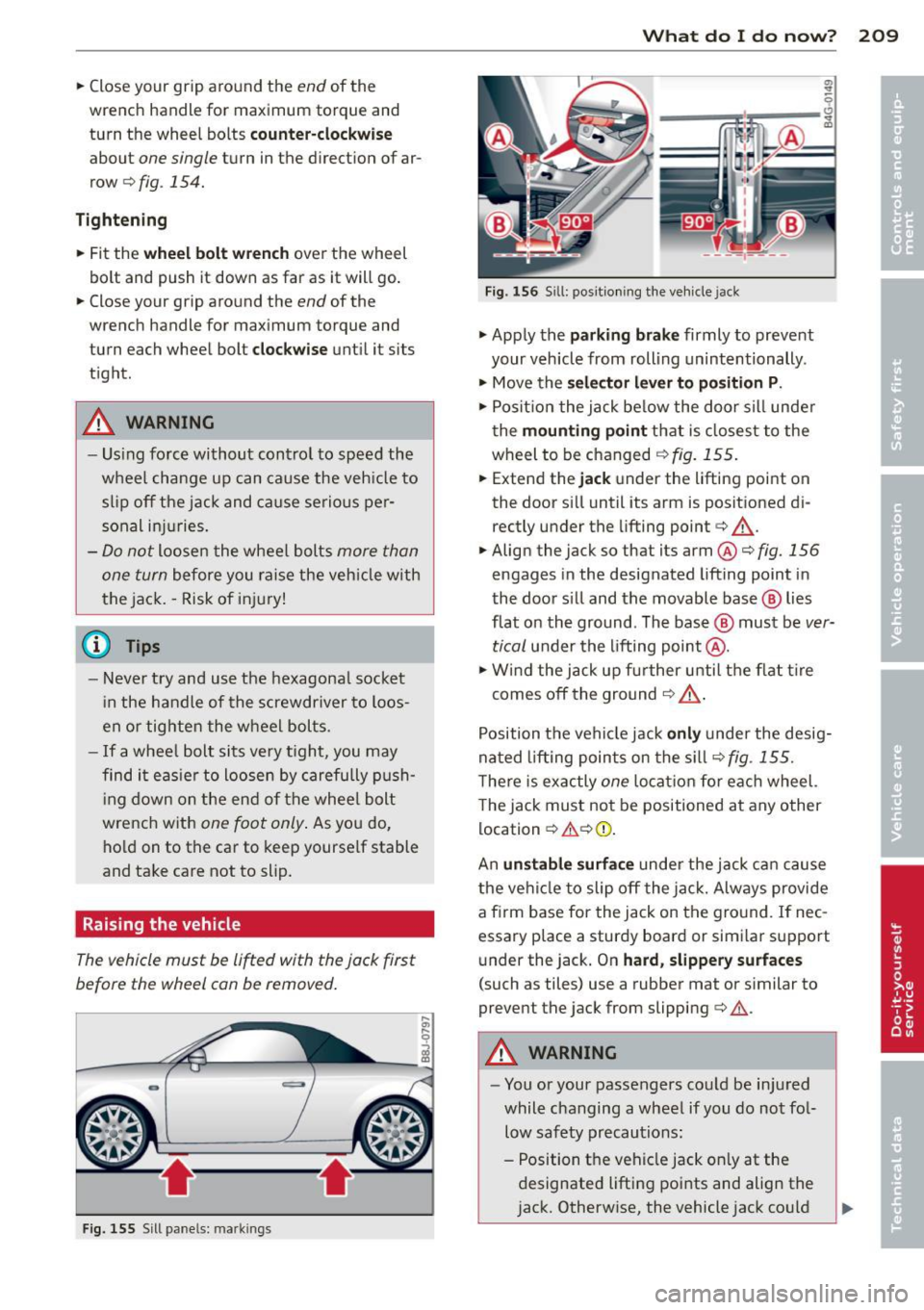
Fig. 155 Sill p ane ls: m arkin gs
What do I do now ? 209
Fig. 1 56 Sill : pos itio ning the ve hicle jac k
.. App ly the pa rkin g brake firmly to prevent
your veh icle from rolling unintentionally .
.. Move the
se lect or lever to p osition P .
.. Posit io n the jack be low the door sill unde r
t he
m ounting point tha t is closest to the
wheel to be changed
r=> fig. 155 .
.. Extend the jack under the lifting point on
the door s ill until its arm is positioned di
rectly under the lifting point
c> ,& .
.. Align the jack so that its arm@¢ fig. 156
engages in the designated lift ing point in
the door s ill and the movable base ® lies
flat on the ground . The base @ must be
ver
tical
under the lifting point @ .
.. Wi nd the jack up fu rther u ntil t he f lat t ire
comes off the ground
c> ,& .
Position t he vehicle jack only under the desig
na ted lifting points on the s ill
r:>fig . 155.
T he re is exactly one locat io n for eac h wheel.
T he jack must not be positioned at any other
location ¢
,&¢(D .
An unstable surfa ce unde r the jack ca n cause
the ve hicl e to slip off the jack. Always provide
a firm base for the jack on the gro und . If nec
essary place a sturdy board or s im ilar support
u nder the jack. On
hard , slippery surf aces
(such as tiles) use a rubber mat or similar to
prevent the jack from slipping ¢
.&.
A WARNING
-You or your passengers cou ld be in jured
while changing a wheel if you do not fo l
low safety precautions:
- Position the veh icle jack on ly at the
designated lifting poi nts and align the
j ack. Otherwise, the vehicle jack co uld
Page 212 of 244
210 What do I do now?
slip and cause an injury if it does not
have sufficient hold on the vehicle.
- A soft or unstable surface under the
jack may cause the vehicle to slip off
the jack. Always provide a firm base for
the jack on the ground . If necessary,
use a sturdy board under the jack.
- On hard, slippery surface (such as tiles)
use a rubber mat or similar to prevent
the jack from slipp ing .
- To help prevent injury to yourself and
your passengers:
- Do not raise the vehicle unti l yo u are
sure the jack is securely engaged.
- Passengers must not remain in the ve
hicle when it is jacked up.
- Make sure that passengers wait in a
safe p lace away from the vehicle and
well away from the roadway and traffic.
- Make sure jack position is correct, ad
just as necessa ry and then continue to
ra ise the jack .
(D Note
A floor jack or the pads on the hoist arms
must
not be posit ioned at the points
shown
-arrows- .
Taking the wheel off
Follow these instructions step-by-step for
changing the wheel.
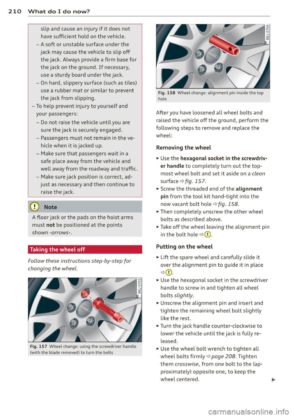
Fig. 157 Wheel ch an ge: us ing the sc rewdrive r hand le
(w ith the b lade removed) to turn the bolts
Fig. 158 Whee l change : alignmen t pin inside the top
hol e
After you have loosened all wheel bolts and
raised the vehicle off the ground, perform the
following steps to remove and replace the
wheel:
Removing the wheel
.,. Use the hexagonal socket in the screwdriv
er handle
to completely turn out the top
most whee l bolt and set it aside on a
clean
surface c;, fig. 15 7.
.,. Screw the threaded end of the
alignment
pin from the tool kit hand-tight into the
now vacant bolt hole <=>
fig. 158 .
.,. Then completely unscrew the other wheel
bolts as described above.
.,. Take off the whee l leaving the alignment pin
in the bolt hole
c;,(D .
Putting on the wheel
.,. Lift the spare wheel and carefully s lide it
over the alignment p in to guide it in place
c;,(D .
.,. Use the hexagonal socket in the screwdriver
handle to screw in and tighten all whee l
bolts
slightly .
.,. Unscrew the alignment p in and insert and
tighten the remaining wheel bolt slightly like the rest .
.,. Turn the jack handle counter-clockwise to
lower the vehicle until the jack is fully re
leased .
.,. Use the wheel bo lt wrench to tighten all
wheel bolts firmly ,=:,
page 208 . Tighten
t hem
crosswise, from one bolt to the ( ap
proximately) opposite one, to keep the
wheel centered.
Page 213 of 244
(D Note
When removing or installing the wheel,
the rim could hit the bra ke rotor and dam
age the rotor . Wor k carefully and have a
second person help you.
N ever use the hexa gonal s ocket in the ha n
d le of the screwdriver to loosen or t ighten
the wheel bolts.
- Pull the reversib le blade from the screw
drive r before yo u use the hexagonal
socket in t he handle to t urn the whee l
bo lts .
- When mounting tires with
unid irectional
tread design
make s ure the tread pat
te rn is poi nte d the r ight way
¢pag e 211.
- The wheel bolts should be clea n and easy
to tu rn . Ch eck for dirt and corros ion on
the mat ing su rfaces of both the whee l
a nd th e hu b. Remove a ll dir t fro m these
s ur fa ces before remo unting the wheel.
Notes on wheel change
Pl ease rea d the information ¢ page 191, New
tires and replacing tires and wheels,
i f you are
going to use a spare t ire which is different
from the tires on your ve hicle.
Afte r you change a tire:
- Check the tire pressure on the spare imme
diately after mounting .
- Have the wheel bolt tightening torque
che cked with a torque wrench as soon as
possible by your authorized Audi dealer or
a qualified service station.
- With steel and alloy wheel rims, the wheel
bolts are correctly tightened at a torque of
90 ft lb (120 Nm) .
- If you notice while changing a tire that the
wheel bolt s are co rroded and diffi cult to
turn , then they should be replaced before
you check the t ightening torque.
What do I do now? 211
- Replace the flat tire with a new one and
have it installed on your vehicle as soon as
possible. Remount the wheel cover .
Until then , drive with extra care and at re
duced speeds.
A WARNING
-
- If you are go ing to e quip your ve hicl e
wit h tires o r rims which differ from those
which were factory installed, t hen be
sure to read the information¢
page 191,
New tires and replacing tires and
wheels .
-Always sto re the tools secu rely in lug
gage compartment. Othe rwise, in a n ac
cident o r su dd en maneuv er they cou ld fly
forwa rd, causi ng injury to passe ngers in
the vehicle.
Tires with unidirectional tread design
Tires with unidirectional tr ead design must be
mounted with their tread pattern pointed the
right dire ction.
A u nidirectional tire can be identified by ar
rows on the sidewall,
which point in the direc
tion of t he rota tion. Yo u m ust follow the
s p ecifie d direction of rot ation. This i s nece ssa
r y in order fo r these tires to develop t heir op
timum charac ter istics regard ing grip, road
no ise, wear, and hydrop la ning.
•
•
Page 214 of 244
212 Fuses and bulbs
Fuses and bulbs
Electrical fuses
Replacing fuses
Fuses that have blown will have metal strips
that have burned through .
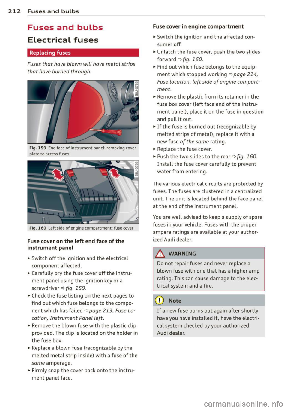
Fig. 159 End face of instrument panel: rem ov ing cover
p la te to access fuses
Fig. 160 Left side of eng ine compart men t: fuse cove r
Fuse cover on the left end face of the
inst rument pane l
.. Switch off the ignition and the electrical
component affected.
.. Carefully pry the fuse cover off the instru
ment panel using the ignition key or a
screwdriver
c;::> fig. 159 .
.. Check the fuse list ing on the next pages to
find out which fuse belongs to the compo
nent which has failed
o page 213, Fuse Lo
cation, Instrument Panel left .
.. Remove the blown fuse with the plastic clip
provided. The cl ip is located on the holder in
the fuse box .
.. Replace a blown fuse (recognizable by the
melted metal str ip ins ide) with a fuse of the
same amperage .
.. Firmly snap the cover back onto the instru
ment pane l face .
Fuse cover in engine compartment
.. Switch the ignit ion and the affected con
sumer off .
.. Unlatch the fuse cover , push the two slides
forward
c;::> fig. 160.
.. Find out which fuse belongs to the equip
ment which stopped working
c;::> page 214,
Fuse location , le~ side of engine compart
ment .
.. Remove the plastic from its retainer in the
fuse box cover (left face end of the instru
ment panel), place it on the fu se in question
and pull it out .
.. If the fuse is burned out (recognizable by
melted strips of metal), replace it with a
new fuse
of the same rating.
.. Replace the fuse cover .
.. Push the two slides to the rear
o fig. 160.
Install the fuse cover carefully to prevent
water from enter ing .
The various electrical circuits are protected by
fuses. The fuses are clustered in a centralized unit. The unit is located behind the face panel
at the end of the instrument panel.
You are well advised to keep a supply of spare
fuses in your vehicle. Fuses with the proper
ampere ratings are available at your author
ized Audi dealer.
A WARNING -
Do not repa ir fuses and never replace a
blown fuse with one that has a higher amp
rating. This can cause damage to the elec
trica l system and a fire.
(D Note
If a new fuse burns out again after shortly
have you have installed it, have the electri
ca l system checked by your authorized
Audi dealer.
Page 215 of 244
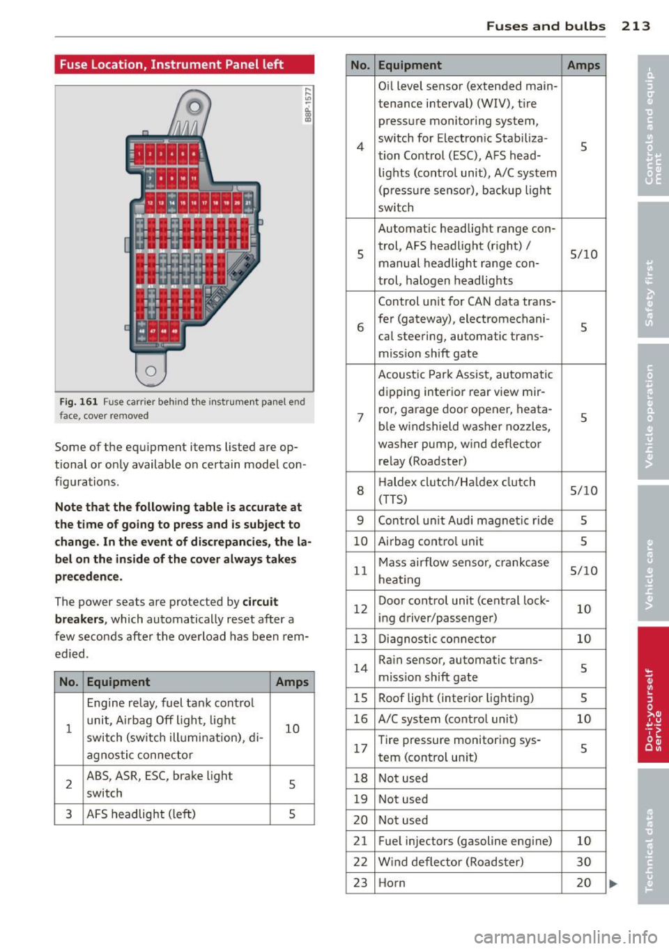
Fuse Location, Instrument Panel left
0
Fig. 161 Fuse carrier behind the instrument panel end
face, cover removed
Some of the eq u i prnent items listed a re op
tional or only available on certain model con
f igurations.
Note that the following table is accurate at
the time of going to press and is subject to
change. In the event of d iscrepancies, the la
bel on the in side of the cover always takes
precedence .
The power seats are protected by circuit
breakers ,
which automatically reset after a
few seconds after the overload has been rem
ed ied.
No. Equipment Amps
Engine relay, fuel tank cont ro l
1
unit, A irbag Off light, light
10 switch (sw itch illumi nation), di-
agnostic connector
2
ABS, ASR, ESC, brake light
5 switch
3 AFS headlight (left) 5
No.
4
5
6
7
8
9
10
11
12
13
14
15
16
17
18
19
20
21 22
23
Fuses and bulbs 213
Equipment Amps
Oil level sensor (extended main-
tenance interval)
(WIV), t ir e
press ure monitoring system,
sw itch for Electron ic Stabiliza-
5 tion Control (ESC), AFS head-
lights (control unit), A/C system
(pressure sensor), backup light
sw itch
Automatic headlight range con- trol, AFS headlight (right) /
5/10
manual headlight range con-
trol, halogen headlights
Control unit for CAN data trans-
fer (gateway), electrornechani-
5 cal steering, automatic trans-
miss ion shift gate
Acoustic Park Assist, automatic
d ip ping interior rear
view rnir-
ror, garage door opener, heata-
5 ble windshield washer nozzles,
washer pump, w ind deflector
relay (Roadster)
H aldex clutch/Ha ldex clutch
5/10 (TTS)
Control un it Audi magnetic ride
5
A irbag contro l unit 5
Mass airflow sensor, crankcase 5/10
heating
Door control unit (central lock -
10 ing driver/passenger)
Diagnostic connector
10
Rain sensor, automatic trans-
5 miss ion sh ift gate
Roof light (interior lighting)
5
A/C system (contro l unit) 10
Tire pressure monitoring sys -
5 tern (control un it)
Not used
Not used
Not used
Fuel injectors (gasoline eng ine)
10
Wind deflector (Roadster) 30
Horn 20
Page 216 of 244
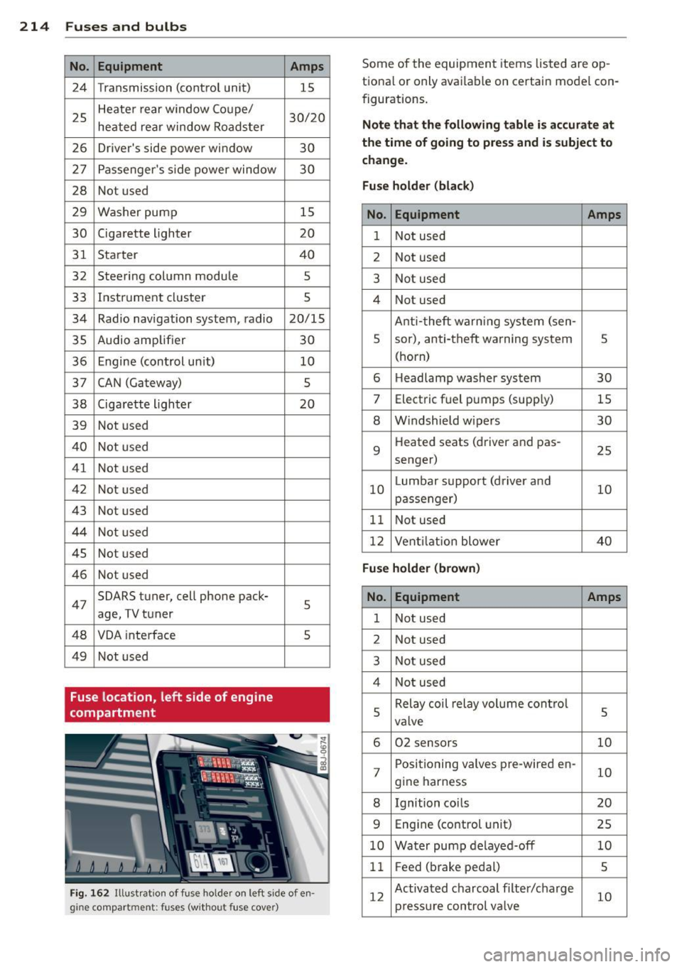
214 Fuses and bulb s
No. Equipment
24 Transmi ssion (contro l un it)
25 Heate
r rear window Coupe /
heated rear window Roadster
26 Driver'
s side power window
27 Passenger's s ide power window
28 No
t used
29 Washer pump
30 Cigarette lighter
31 Start er
32 Steering column module
33 Instrument clust er
34 Radio navigation system , radio
35 Aud io amplifi er
36 Engine (control un it)
37 CAN (Gat
eway)
38 Ciga
rette lighter
39 Not us ed
40 Not used
4 1 Not u sed
42 Not used
43 No t used
44 Not used
45 No
t used
46 Not used
47 SOARS tuner, cell phone pack-
age,
TV tuner
48 VOA interface
49 Not used
Fuse location, left side of engine
compartment Amps
15
30/ 20
30 30
15
20
40 5
5
20/15
30 10
5
20
5 5
Fi g. 162 Ill ustra tion of fus e ho lde r on l eft side o f en·
gi ne compar tment: fuse s (withou t fuse c over)
Some of the equipment items listed are op
tiona l or only avai lable on c ertain mod el con
figurations.
Note tha t the foll owing table i s ac cur ate at
the time of going to pre ss and is subject to
change .
Fus e holder (bla ck )
No . Equipment Amps
1 Not used
2 Not used
3 Not used
4 No t used
Anti- theft warning system (sen -
5 sor), ant
i-theft warn ing system
5
(horn)
6 Headlamp washer system
30
7 Elec
tric fuel pumps (supp ly)
15
8 W
indshield wipers
30
9 H
eat ed seats (dr iver and pas-
25
senger)
10 L
umbar support (d river and
10
passenger)
11 Not u sed
12 Vent ilation blower 40
Fus e holder (brown )
No. Equipment Amps
1 Not used
2 Not used
3 Not used
4 Not used
5 Relay coil
relay volume cont ro l
5
va lve
6 02
sensors
10
7 P
ositioning valves pre-wired en-
10
gine harness
8 Ignition coi ls 20
9 Eng
in e (cont rol unit)
25
10 Water pump de layed-off 10
1 1 F
e e d (brak e pedal)
5
1 2 Activated charcoal filter/charge
10
p ress ure control va lve
Page 217 of 244
Bulbs
Replacing light bulbs
For your safety, we recommend that you have
your authorized Audi dealer replace burned
out bulbs for you .
It is becoming increasingly more and more
difficult to replace vehicle light bulbs since in many cases, other parts of the car must first
be removed before you are able to get to the
bu lb. This appl ies especially to the light bu lbs
in the front of your car which you can on ly
reach through the engine compartment .
Sheet metal and bulb ho lde rs can have sharp
edges that can cause ser ious cuts, and parts
must be correctly taken apart and then prop
erly put back together to help prevent break
age of parts and long term damage from wa
ter that can enter housings that have not been
properly resealed.
F or your safety, we recommend that you have
your authorized Audi dealer replace any bulbs
for you, since your dealer has the proper tools,
the correct bu lbs and the expertise.
G as disc harge la mp s (X enon li ght s)*:
Due to the high electrical voltage, have the
bu lbs rep laced by a qualified technician.
H eadlights with Xenon l ight can be ident ified
by the high voltage sticker .
A WARNING
Contact with hig h-voltage components of
the electrica l system and improper re
placement of gas discharge (Xenon) head
light bulbs can cause serious personal in
jury and death .
- Xenon bulbs are pressurized and can ex plode when be ing changed.
- Chang ing Xenon lamps requires the spe
c ial train ing, instructions and equip
ment.
- Only an authorized Aud i dea ler or other
qualified workshop should change the
bulbs in gas discharge lamps .
Fuses and bulb s 215
A WARNING
There are parts with sharp edges on the
openings and on the bulb holders that can
cause ser ious cuts.
- If you are uncertain about what to do,
have the work performed by an author
ized Audi dealer or other qualified work
shop. Ser ious personal i nju ry may result
from imprope rly perfo rmed wo rk.
(D Tips
- If you must replace the light bulbs your
self, always remember that the eng ine
compartment of any vehicle is a hazard
ous area to work in. A lways read and
heed a ll WARN INGS
°* page 164, Work
ing in the engine comportment"*&. .
- It is best to ask your authorized Audi
dealer whenever yo u need to change a
bulb .
• -
•
Page 218 of 244
216 Emergency situations
Emergency situations
General
This chapter is intended for trained emer
gency crews and working personnel who
have the necessary tools and equ ipment to
perform these ope rations.
Starting by pushing or
towing
Q;) Note
Vehicle s with an automati c transmission
cannot be started by pushing or towing .
Starting with jumper
cables
If necessary, the engine can be started by
connecting it to the battery of another vehi
cle.
If the engine should fail to start because of a
discha rged or wea k batte ry, the battery can be
connected to the battery o f
another vehicle,
using a
pair of jumper cables to start the en
g ine .
Jumper cables
Use only jumper cab les of sufficiently
large cross section to safely carry the starter
cur rent. Refer to the manufacturer's specifica
ti ons.
Use on ly jumper cables which have
insulated
termina l clamps and are properly marked for
d istinction :
plus(+) cable in most cases colo red red
minu s(-) cable
in most cases colo red black .
_& WARNING
Batterie s contain elec trici ty, a cid, and ga s.
Any of th ese c an cause ve ry seri ous or f ata l
inju ry . Follow the instructions below fo r
safe han dling of your ve hicle's battery.
- Alw ays s hield yo ur eyes and avoid lean
ing over the batte ry w henever possib le . -
A discharged battery can a lready freeze
at temperatures just be low 32 °F (0 °C).
Before connect ing a jumper cab le, the
frozen battery must be thawed com
p letely, othe rwise it cou ld explode .
- Do not allow batte ry acid to contact eyes
or skin . Fl ush any contacted a rea wi th
water immediat ely .
- Imp roper use of a booster battery to
s tart a vehicle may cause an explosion.
- Vehicle batter ies generate explosive gas
es . Keep sparks, flame and lighted ciga
rettes away from ba tte ries .
- Do not try to jump start a ny ve hicle w ith
a low ac id leve l in the battery .
- The vo ltage of the booster batte ry m ust
a lso have a 12-Vo lt rat ing . The capacity
(A h) of the booster batte ry should not b e
lowe r than that of the discharged bat
tery . U se o f batt erie s of d iffe ren t voltage
or subs tanti ally diffe ren t "Ah" rat ing
may c ause an exp losion and person al in
ju ry .
- N ever ch arge a fr ozen bat te ry. Gas t rap
ped in the ice may ca use an ex plosion .
- N ever ch arge o r use a batt ery th at has
been fro zen. T he battery case may have
be weakened.
- Us e of batt erie s of di ffere nt vo lta ge or
substan tially differen t ca pa city (Ah) rat
i ng may cause an exp losion and injury.
T he capac ity (Ah) of the booster battery
should not be lower than that of the dis
charged batte ry.
- Before you check anything in the engine
compartment, always read and heed a ll
W ARNI NGS
c::;,page 164, Working in the
engine compartment .
@ Note
-App lying a hig her voltage booster ba t
tery will cause expens ive damage to se n
sitive electronic components, such as
cont ro l units , relays, rad io, etc.
- There must be no electrical contact be
twee n the vehicles as otherwise current
cou ld already start to flow as soo n as th e
posi tive (+) term inals are connect ed. ""
Page 219 of 244
@ Tips
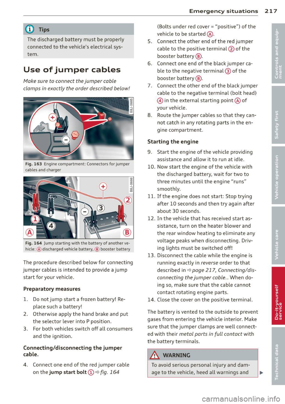
The discharged battery must be properly connected to the vehicle's electrical sys
tem.
Use of jumper cables
Make sure to connect the jumper coble
clomps in exactly the order described below!
Fig. 163 Eng ine compartme nt: Co nnecto rs for jumper
cables and charger
F ig . 164 Jump start ing with the battery of another ve
h icle: @discharged ve hicle batte ry, @ booste r battery
The procedure described below for connecting
jumper cables is intended to provide a jump
start for your veh icle.
Preparatory me asures
1. Do not jump start a frozen battery! Re
place such a battery!
2 . Otherwise apply the hand brake and put
the selector leve r into P pos ition.
3. For both vehicles swi tch off all cons umers
and the ignit ion.
Conn ecting /disconnecting the jumper
cable .
4. Con nect one end of the red jumper cable
on the
jump st a rt bo lt @ ¢ fig. 164
Emergenc y situ ation s 21 7
(Bolts under red cover = "positive") o f the
vehicle to be started @.
5 . Connect the other end of the red jumper
cable to the positive terminal @ofthe
booster battery @.
6 . Connect one end of the black jumper ca
ble to the negat ive terminal ® of the
booster battery @.
7. Co nnect the othe r end of the black jumper
c able to the negat ive termina l (bolt head)
@ in the external starting po int @ of
your vehicle.
8 . Route the jumper cables so that they can
not catch in any rotat ing parts in the en
gine compartment.
Sta rting th e engine
9. Sta rt the eng ine of the vehicle providing
assistance and allow it to run at idle.
10. Now start the engine of the vehicle with
the discharged battery, wait for two to
three minutes until the engine "runs"
smooth ly.
11. If the eng ine does not start: Stop try ing
after 10 seconds and then try aga in after
about 30 seconds.
12 . In the vehicle that has received sta rt as
s istance, tur n on the heate r blower and
the rear window hea ting to elim inate a ny
vo ltage peaks when disconnecting . Driv
ing lights must be switched off!
13 . Disconnect the cable while the engine is
runn ing exactly in
reverse order to that
described in<=>
page 217, Connecting/dis
connecting the jumper coble ..
When do
ing so, make sure that the cable cannot
contact rotating eng ine parts.
14 . Close the cove r on the posit ive termina l.
T he battery is vented to the outside to p revent
gases from enter ing the veh icle inter ior. Make
s ur e that the jumper clamps a re well connec t
ed with their
me tal parts in full contact with
the battery terminals.
A WARNING
To avoid serious personal injury and dam
age to the vehicle, heed all warnings and
Page 220 of 244
218 Emergency sit uat ions
instructions of the jumper cable
manufacturer. If in doubt, call for road
service.
- Jumper cables must be long enough so
that the vehicles do not touch.
- When connecting jumper cables, make
sure that they cannot get ca ught in any
moving parts in the eng ine compart
ment.
- Before you check anything in the engine
compartment, always read and heed all
WARNINGS
¢ page 164, Working in the
engine compartment.
@ Note
Improper hook-up of jumper cables can ru
in the generator.
- Always connect POSITIVE(+) to POSI TIVE(+), and NEGATIVE( -) to NEGATIVE
( - ) ground post of the battery manager
control unit.
- Check that all screw plugs on the battery
cells are screwed in firmly . If not, tighten
plugs prior to connecting clamp on nega
tive battery terminal.
- Please note that the procedure for con nect ing a jumper cable as desc ribed
above applies spec ifically to the case of
you r vehicle being j ump s tarted. When
you are giv ing a jump star t to anothe r ve
hicle, do
not connect the negat ive (-) ca
ble to the negative(-) terminal on the
discharged battery ©- Instead, securely
connect the negative(-) cable to either a
solid metal component that is firmly
bo lted to the engine block or to the en
gine block itself. If the battery that is be
i ng charged does not vent to t he outside,
escaping batte ry gas cou ld ig nite and ex
plode!
Emergency towing
with commercial tow
truck
General hints
Your Audi requires special handling for tow
ing.
T he following information is to be used by
commercial tow truck operators who know
how to operate their equipment safely.
- Nev er tow your Audi , towing will cau se
damage to the engine and tr an smi ssion .
- Ne ver wrap th e safet y chain s or winch ca
ble s ar ound the brak e lines.
- To prevent unne ces sary damage , your Audi
must be tran sp o rt ed with a car carrier
(flatbed truck ).
- To load th e vehi cle on t o the flat bed , u se
the t owing loop found in t he vehicle tools
and attach to the front o r rear ancho rage
¢page 219 and ¢page 220 .
A WARNING
-A vehicle being towed is not safe for pas-
sengers. Never allow anyone to ride in a
vehicle be ing towed, for any reason.
-