ECO BMW 525i 1997 E39 Workshop Manual
[x] Cancel search | Manufacturer: BMW, Model Year: 1997, Model line: 525i, Model: BMW 525i 1997 E39Pages: 1002
Page 487 of 1002
Downloaded from www.Manualslib.com manuals search engine
.- .
Fuel Tank and Fuel Pump
- To reinstall:
Use new sealing ring at tank collar.
* Align tab of sending unit with matching recess in opening
of tank.
Be sure that fuel line connections point in same direction
as they came out.
Reconnect harness connector and hose.
Fill tank and check for leaks by running engine.
Install access cover and its mounting fasteners.
CAUTIOI\C
After finishing repairs but before starting engine, be sure
there is at least
5 liters (1.5 gallons) of fuel in the tank. The
NOTE-
It is common practice to replace the fuel filter when the fuel
pump
unit is replaced. See 020 Maintenance.
Tightening torque
Tank collar locking ring to tank 35 Nm (26 lb-ft)
Fuel level sender (left side),
removing and installing
The procedure for removing and replacing the left side fuel
level sender is
simllar to that used for the r~ght side. There is
no fuel pump on the left side.
- Remove rear seat lower cushion by lifting off catches at front.
- Expose left side access cover:
- Peel forward lip of carpet.
Release rubber grommet from center of access cover
insulation.
Peel back insulation at
perforations to expose fuel tank
access cover.
Remove cover to expose electrical harness connector.
WARNING-
Fuel may be spilled. Do not smoke or work near heaters or
other fire hazards.
When disconnecting fuel hose, wrap shop rag around
end of hose to prevent spray of fuel under pressure.
Page 488 of 1002
Downloaded from www.Manualslib.com manuals search engine
/ ~uel Tank and Fuel Pump
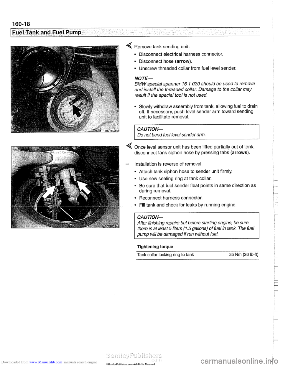
4 Remove tank sending unit:
Disconnect electrical harness connector.
Disconnect hose (arrow).
- Unscrew threaded collar from fuel level sender.
NOTE-
BMW special spanner 16 1 020 should be used to remove
and install the threaded collar. Damage to the collar may
result if the special tool is not used.
Slowly withdraw assembly from tank, allowing fuel to drain
off. If necessary, push level sender arm toward sending
unit to facilitate removal.
CA UTIOW-
Do not bend fuel level sender arm.
4 Once level sensor unit has been lifted partially out of tank,
disconnect tank siphon hose by pressing tabs (arrows).
- Installation is reverse of removal
Attach tank siphon hose to sender unit firmly.
Use new sealing ring at tank collar.
. Be sure that fuel sender float points in same direction as
during removal.
- Reconnect harness connector.
Fill tank and
check for leaks by running engine.
CAUTION-
After finishing repairs but before starting engine, be sure
there is at least
5 liters (1.5gallons) of fuel in tan/(. The fuel
pump will be damaged if run without fuel.
Tightening
torque
Tank collar loclting rlng to tanlt 35 Nm (26 lb-ft) -
Page 489 of 1002
Downloaded from www.Manualslib.com manuals search engine
7 .- A Fuel Tank and Fuel Pump
Siphon pump, removing and installing
The fuel compensating siphon pump equalizes fuel level
between the two fuel tank lobes.
- Drain fuel tank as described later,
WARNING -
Fuel may be spilled. Do not smoke or work near heaters or
other fire hazards.
- Remove left and right fuel level sensors and fuel pump as
described earlier.
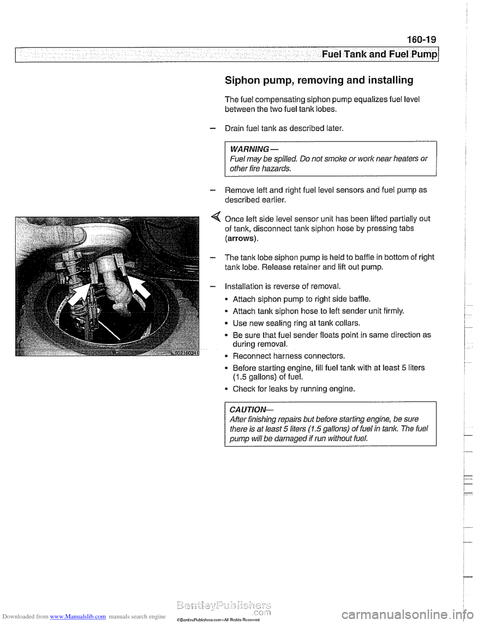
4 Once left side level sensor unit has been lifted partially out
of tank, disconnect tank siphon hose by pressing tabs
(arrows).
- The tank lobe siphon pump is held to baffle in bottom of right
tank lobe. Release retainer and lift out pump.
- Installation is reverse of removal.
Attach siphon pump to right side baffle.
Attach tank siphon hose to left sender unit firmly.
Use new sealing ring at tank collars
Be sure that fuel sender floats point in same direction as
during removal.
Reconnect harness connectors.
. Before starting engine, fill fuel tank with at least 5 liters
(1.5 gallons) of fuel.
Check for
leaks by running engine.
Afler finishing repairs but before starting engine, be sure
Page 490 of 1002
Downloaded from www.Manualslib.com manuals search engine
--
I Fuel Tank and Fuel Pump
The plastic fuel tank is mounted underneath the center of the
car (underneath the rear seat). Mounted in the fuel tank are
the fuel pump and fuel level sending units. Connecting lines
for the evaporative emission control system and expansion
tank are also attached to the tank.
Fuel
tank capacity for E39 models
Tank capacity
70 liters (18.5 gal)
Reserve capacity
8 liters (2.1 gal)
Fuel tank, draining
Drain fuel tank into a safe storage unit using an approved fuel
pumping device.
WARNING-
# Before removing tank, be sure that all hot components,
such as the exhaust system, are completely cooled down.
Fuel may be spilled. Do not smoke or
work near heat-
ers or other fire hazards.
- Start engine and allow to run 10 - 15 seconds to fill fuel com-
pensating siphon assembly. This will allow both lobes of fuel
tank to he drawn off through fuel filler pipe,
- Disconnect negative cable from battery.
CAUTION-
Prior to disconnecting the batteg read the battery discon-
nection cautions given
in 001 General Warnings and Cau-
tions.
- Remove fuel tank filler cap
- Slide suction hose into filler neck about 130 cm (51 in.), twist-
ing as necessary. Withdraw fuel into storage unit.
- Monitor fuel level reduction in both lobes:
- Remove rear seat cushion and access both fuel tank send-
er harness connectors.
Use multimeter to measure resistance at both senders,
Resistance should drop as fuel level drops.
- If siphoning mechanism is faulty, drain left tank lobe sepa-
rately by removing sender cover and pumping fuel directly
out of left lobe.
Page 494 of 1002
Downloaded from www.Manualslib.com manuals search engine
Fuel Tank and Fuel Pump 1
Activated carbon canister I fuel tank leak
detection unit
(LDP or DMTL), removing . . -
and installing
- Raise rear end of car and support safely.
CAUTION-
Make sure the car is stable and well supported at all times.
Use a professional automotive lift
orjack stands designed for
the purpose.
A floor jack is not adequate support.
- Remove left rear wheel and inner fender panel
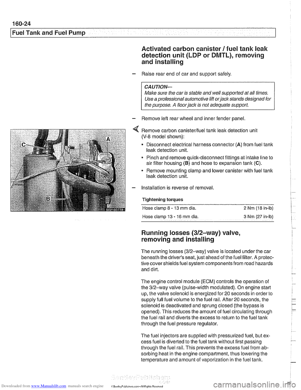
Remove carbon canisterlfuel tank leak detection unit
(V-8 model shown):
Disconnect electrical harness connector
(A) from fuel tank
leak detection unit.
Pinch and remove quick-disconnect fittings at intake line to
air filter housing
(5) and hose to expansion tank (C).
* Remove mounting clamp and lower canister with fuel tank
leak detection unit.
Installation is reverse of removal.
Tightening
torques
Hose clamp 8 - 13 mm dia. 2 Nrn (18 in-lb)
Hose clamp
13 - 16 rnm dia 3 Nm (27 in-lb)
Running losses (312-way) valve,
removing and installing
The running losses (312-way) valve is located under the car
beneath the driver's seat, just ahead of the fuel filter. A protec-
tive covershieldsfuel system components from road hazards
and dirt.
The engine control module
(ECM) controls the operation of
the 312-way valve (pulse-width modulated). On engine start
up, the valve solenoid is energized for 20 seconds in order to
supply full fuel volume to the fuel rail.
After20 seconds, the
solenoid is deactivated and sprung closed (the bypass is
opened). This reduces the amount of fuel circulating through
the fuel rail and diverts the excess to return to the fuel tank
through the fuel pressure regulator.
The fuel injectors are supplied with pressurized fuel, but ex-
cess fuel is diverted to the fuel tank without first passing
through the fuel rail. This prevents the excess fuel from ab-
sorbing heat in the engine compartment, thus lowering the
temperature and amount of vaporization in the fuel tank.
Page 503 of 1002
Downloaded from www.Manualslib.com manuals search engine
Warnings and cautions
Obse~e the following warnings and cautions when worlting
on the cooling system.
WARNING -
. At normal operating temperature the cooling system is
pressurized. Allow the system to cool as long as possible
before opening (a minimum of one hour), then release the
cap slowly to allow safe release ofpressure.
a Releasing the coolant system pressure lowers the cool-
ant boilingpoint and the coolant may boil suddenly. Use
1 heavy and wear eye and face protection to
guard against scalding.
Use extreme care when draining and disposing of en-
gine coolant. Coolant is poisonous and lethal to hu-
mans andpets. Pets are attracted to coolant because
of its sweet smell and taste. Seek medical attention im-
mediately if coolant is ingested.
CAUTIOG
Avoid adding cold water to the coolant while the engine is
hot or overheated. If it is necessary to add coolant to a
hol
system, do so only with the engine running and coolanl
pump turning.
To avoid excess silicate gel precipitation in the cooling
system and loss of cooling capacity, use BMW coolant
or equivalent low silicate antifreeze.
a If oil enters the cooling system, the radiator, expansion
tank and heating circuit must be flushed with cleaning
agent. BMW recommends removal of the radiator and
expansion
tank to flush.
When
worlcing on the cooling system, cover the alter-
nator to protect it against coolant drips.
Prior to disconnecting the battery, read the battery dis-
connection cautions given in
001 General Warnings
and Cautions.
Begin the diagnosis of cooling system problems with a thor-
ough visual inspection.
If no visual faults are found, it is rec-
ommend that the engine control module (ECM) fault memory
be checked for stored diagnostic trouble codes
(DTCs) using
BMW scan tool
DlSplus or equivalent.
Page 504 of 1002
Downloaded from www.Manualslib.com manuals search engine
170-8
I Radiator and Cooling System
Common cooling system faults can be grouped into one of 4
categories:
Cooling system
lealts
Poor coolant circulation
Radiator cooling fan faults
Electrical/electronic faults
Cooling system inspection
- Check that coolant pump drive belt tensioner is functioning
properly and that belt tension is correct. Belt tensioner sys-
tems for the different models are shown in
020 Maintenance.
- Check condition of coolant pump drive belt.
- Checlc coolant hoses for cracks or softness. Checlc clamps
for looseness. Check coolant level and check for evidence of
coolant
lealts from engine.
- Check that radiator fins are not blocked with dirt or debris.
Clean radiator using low-pressure water or compressed air.
Blow outward, from engine side out.
- To check coolant pump:
Remove mechanical cooling fan. See Mechanical
(vis.
cous clutch) cooling fan, removing and installing.
Remove drive belt from coolant pump pulley. See
020
Maintenance.
Firmly grasp opposite sides of pulley and check for play in
all directions.
Spin pulley and check that shaft runs smoothly without
play.
NOTE-
The coolant provides lubrication for the pump shaft, so an oc-
casional drop of coolant
lealing from the pump is acceptable.
If coolant drips steadily from the vent hole, replace the pump.
- At normal engine operating temperature, cooling system is
pressurized. This raises boiling point of coolant.
Leaks may
prevent system from becoming pressurized. If visual evi-
dence is inconclusive, pressure test cooling system as de-
scribed later to help pinpoint hard-to-find leaks.
- If cooling system is full of coolant and holds pressure:
- Use an appropriate scan tool to interrogate engine control
module (ECM) for radiator fan or DME control circuit faults.
Checlc for loose or worn drive belt.
0 Test for failed thermostat or coolant pump impeller. Some
pumps may be fitted with plastic impellers.
Page 512 of 1002
Downloaded from www.Manualslib.com manuals search engine
170-1 6
I Radiator and Cooling System
- Remove fan and fan shroud mounting fasteners. Slide fan
and fan shroud downward to remove.
- Reinstallation is reverse of removal.
Thermostat, removing and installing
(M52 engine)
The coolant thermostat is installed in a housing at the front of
the engine.
- Drain coolant from radiator and engine block. See Coolant,
draining and filling (6-cylinder models).
WARNING -
Allow the cooling system to cool before opening or draining
the system.
- Remove mechanical cooling fan and fan shroud. See Me-
chanical (viscous clutch) cooling fan, removing and in-
stalling.
- Disconnect coolant hoses from thermostat housing.
- Remove thermostat housing from front of engine.
- Remove thermostat. Note thermostat direction and orienta-
tion before removing.
- Installation is reverse of removal, noting the following:
- Use new O-ring and gasket(s) when installing thermostat
and housing.
NOTE-
Some thermostats have a direction arrow or vent hole near
the edge. Install the thermostat so that either the arrow or
hole are at the top.
Fill system with coolant as described in Coolant, draining
and filling (6-cylinder models).
CAUTION-
Be sure to reconnect ground wire@) at thermostat housing
mounting bolt, where applicable.
Page 524 of 1002
Downloaded from www.Manualslib.com manuals search engine
180-2
Exhaust System
The exhaust system is designed to be maintenance free, al-
though regular inspection is warranted due to the harsh oper-
ating conditions. Under normal conditions, the catalytic
converter does not require replacement unless it is damaged.
New fasteners, clamps, rubber mounts and gaskets should
be used when replacing exhaust components.
A liberal appli-
cation of penetrating oil to the exhaust system nuts and bolts
in advance may make removal easier.
WARNING -
The exhaust system and catalytic converter operate at
very high temperatures. Allow components to cool before
servicing. Wear protective clothing to prevent burns.
Do not use flammable chemicals near a hot
cataiyiic
converter.
Corroded exhaust system components crumble easily
and often have exposed sharp edges. To avoid injury,
wear eye protection and heavy gloves when working
Exhaust system, removing and installing
The removal and installation procedures given here are gen-
eral procedures for all models. The removal of the exhaust
system as a complete unit is recommended. Once the com-
plete system is removed from the car, individual pipes and
mufflers can be more easily replaced.
WARNING-
Exhaust gases are colorless, odorless, and very toxic. Run
the engine only in a well-ventilated area. Immediately repair
any
leaks in the exhaust system or structural damage to the
car body that
might allow exhaust gases to enter the passen-
ger compartment.
CAUTION-
Use care not to drag or bang oxygen sensors. Oxygen sen-
sors can be easily ruined.
Page 527 of 1002
Downloaded from www.Manualslib.com manuals search engine
Exhaust system1
Exhaust manifold removal procedures are organized accord-
ing to engine code. If necessary, see
100 Engine-General
for engine code and application information.
Exhaust manifolds, removing and installing
(M52 engine)
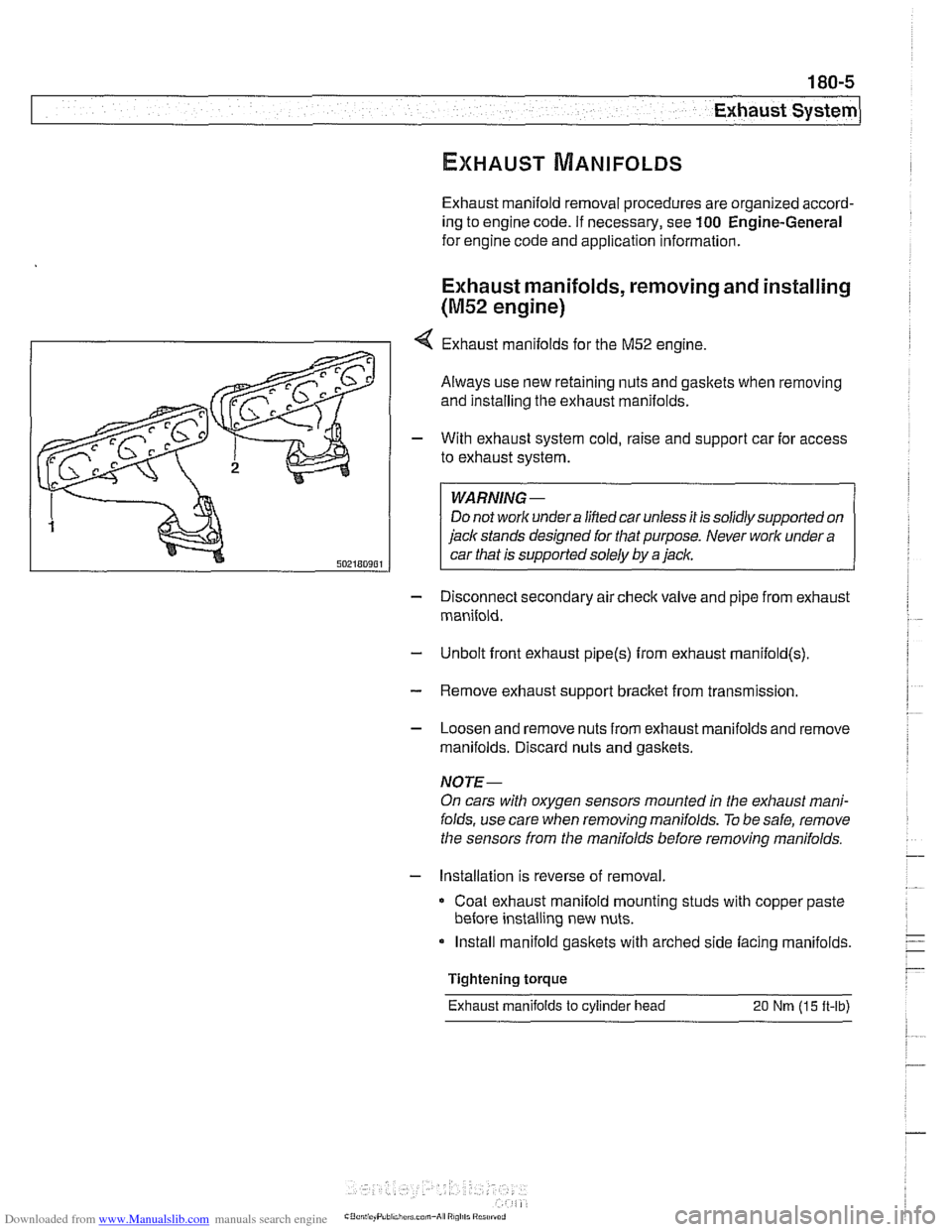
4 Exhaust manifolds for the M52 engine.
Always use new retaining nuts and gaskets when removing
and installing the exhaust manifolds.
- With exhaust system cold, raise and support car for access
to exhaust system.
WARNING -
Do not work under a lined car unless it is solidly supported on
jack stands designed for that purpose. Never work under a
car that is supported solely by a jack.
- Disconnect secondary air check valve and pipe from exhaust
manifold.
- Unbolt front exhaust pipe@) from exhaust rnanifold(s)
- Remove exhaust support bracket from transmission.
- Loosen and remove nuts from exhaust manifolds and remove
manifolds. Discard nuts and gaskets.
NOTE-
On cars with oxygen sensors mounted in the exhaust mani-
folds, use care when removing manifolds.
To be safe, remove
the sensors from the manifolds before removing manifolds.
- Installation is reverse of removal
Coat exhaust manifold mounting studs with copper paste
before installing new nuts.
Install manifold gaskets with arched side facing manifolds.
Tightening torque
Exhaust manifolds
to cylinder head 20 Nm (15 ft-lb)