ECO BMW 525i 1997 E39 Workshop Manual
[x] Cancel search | Manufacturer: BMW, Model Year: 1997, Model line: 525i, Model: BMW 525i 1997 E39Pages: 1002
Page 351 of 1002
Downloaded from www.Manualslib.com manuals search engine
120-3
Ignition System
Warnings and cautions
The ignition system produces dangerous high voltage. In ad-
dition the sensitive electronic components can be damaged
if
proper precautions are not adhered to.
WARNING-
* Do not touch or disconnect any cables from the coils while
the engine is running or being
cranked by the starter.
The ignition system produces high voltages that can be
fatal. Avoid contact with exposed terminals. Use ex-
treme caution when working on a car with the ignition
switched on or the engine running.
- Connect and disconnect tlie DME system wiring and
test equipment leads only when the ignition is
OFF:
Before operating the starter without starting the engine
(for example when
making a compression test) always
disable the ignition.
CA
U TIOW-
Do not attempt to disable the ignition by removing the coils
from the spark plugs.
Connect or disconnect ignition system wires, multiple
wire connectors, and ignition test equipment leads only
while the ignition is
off Switch multimeter functions or
measurement ranges only with the test probes discon-
nected.
* Do not disconnect the battery while the engine is run-
ning.
A high impedance digital multimeter should be used for
all voltage and resistance tests. An LED test light
should be used in place of an incandescent-type test
lamp.
In general, make test connections only as specified by
BMW as described in this manual, or as described by
the instrument manufacturer.
Engine management
BMW €39 engines use an advanced engine management
system known as Digital Motor Electronics (DME). DME in-
corporates on-board diagnostics, fuel injection, ignition and
other engine control functions. DME variants are listed in
Table a. Engine management systems.
Second generation On-Board Diagnostics
(OED II) is incor-
porated into the engine management systems used on the
cars covered by this manual. Use a BMW-specific electronic
scan tool, or a "Generic"
OED II scan tool to access Diagnos-
tic Trouble Codes (DTCs). DTCs can help pinpoint ignition
ine management problems.
Page 354 of 1002
Downloaded from www.Manualslib.com manuals search engine
120-6
lgnition System
lgnition system, troubleshooting
Troubleshooting ignition system faults should begin with an
interrogation of the On-Board Diagnostics (OBD
II) system.
The OBD
II system detects ignition system misfire and other
related faults. When faults are detected, the OBD
II system
stores a Diagnostic Trouble Code (DTC) in the Engine Con-
trol Module (ECM) along with other pertinent fault information.
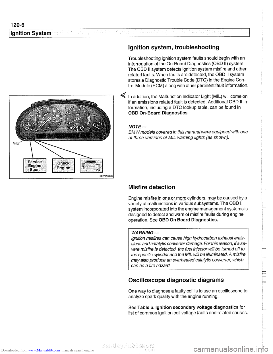
4 In addition, the Malfunction Indicator Light (MIL) will come on
if an emissions related fault is detected. Additional OBD
II in-
formation, including a DTC lookup table, can be found in
OED On-Board Diagnostics.
NOTE-
BMWmodels covered in this manual were equipped with one
of three versions of
MIL warning lights (as shown).
Misfire detection
Engine m~sfire in one or more cylinders, may be caused by a
var~ety of malfunctions in various subsystems. The OBD II
system ~ncorporated into the engine management systems is
des~gned to detect and warn of misfire faults during englne
operat~on. See OED On Board Diagnostics.
WARNING -
lgnition misfires can cause high hydrocarbon exhaust emis-
sions andcatalytic converter damage. For this reason, if a se-
vere misfire is detected, the fuel injector
will be turned off to
the specific cylinder and the
MIL will be illuminated. A misfire
may also produce an overheated catalytic converter, which
can be a fire hazard.
Oscilloscope diagnostic diagrams
One way to diagnose a faulty coil is to use an oscilloscope to
analyze spark quality with the engine running.
See Table b. lgnition secondary voltage diagnostics for
list of common ignition
coil voltage faults and related causes.
Page 355 of 1002
Downloaded from www.Manualslib.com manuals search engine
120-7
Ignition System
Spark plug electrode gap /Too small /TOO big
Table
b. Ignition secondary voltage diagnostics
Secondary
voltage low
Fuel air mixture
I I Too lean
Secondary
voltage high
Spark plug electrode
Worniburnt
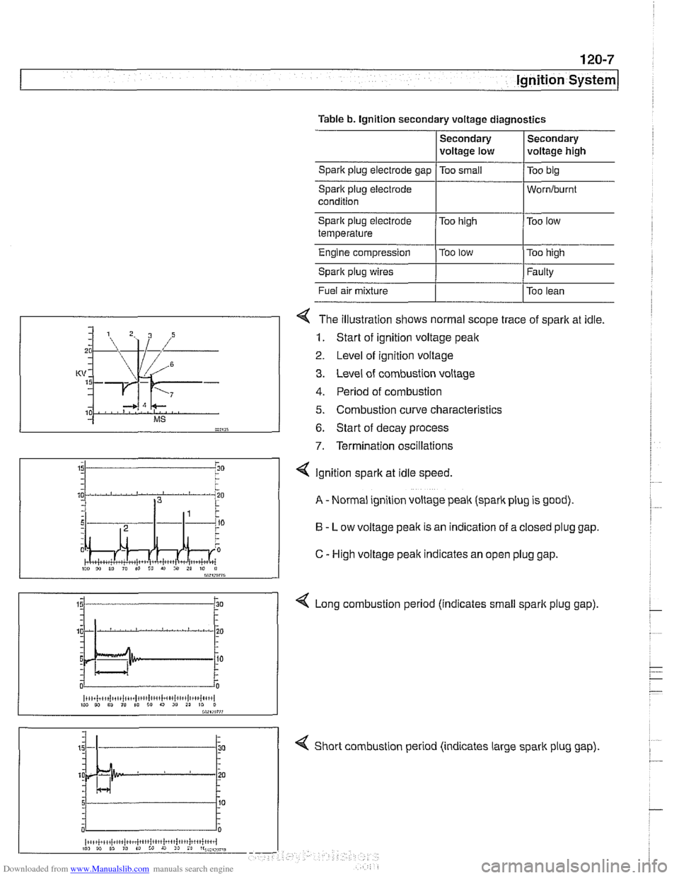
4 The illustration shows normal scope trace of spark at idle.
1. Start of ignition voltage peak
2 Level of ignition voltage
3. Level of combustion voltage
4. Period of combustion
5. Combustion curve characteristics
6. Start of decay process
7. Termination oscillations
Spark plug electrode
temperature
Engine compression
Spark plug wires
4 Short combustion period (indicates large spark plug gap).
Too
high
Too
low
I"" 9, 10 I" to I!, r) i" 21 10 il bW,rn?7G
Too low
Too high
Faulty
4 Ignition spark at idle speed.
A - Normal ignition voltage peak (spark plug is good).
B - Low voltage peak is an indication of a closed plug gap.
C
- High voltage peak indicates an open plug gap.
< Long combustion period (indicates small spark plug gap).
~i,+i!,~,i~tiii~iit~~,t1!lc,',l~~4~l~,~,l,~+~{+',,l 1W W Sl ,@ 10 :o 9 20 21 10 0
Page 357 of 1002
Downloaded from www.Manualslib.com manuals search engine
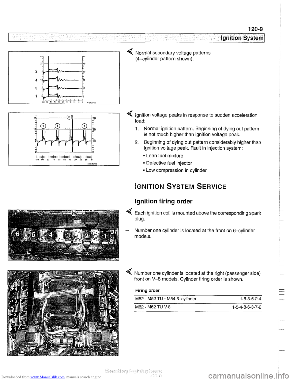
< Ignition voltage peaks in response to sudden acceleration
load:
1. Normal ignition pattern. Beginning of dying out pattern
is not much higher than ignition voltage peak.
2. Beginning of dying out pattern considerably higher than
ignition voltage peak. Fault in injection system:
Lean fuel mixture
Defective fuel injector
Low compression in cylinder
-, :I 1- i :
Ignition firing order
Normal secondary voltage patterns
(4-cylinder pattern shown).
4 Each ignition coil is mounted above the corresponding spark
plug.
- Number one cylinder is located at the front on 6-cylinder
models.
Number one cylinder is located at the right (passenger side)
front on
V-8 models. Cylinder firing order is shown.
Firing order
M52 - M52 TU - M54 6-cylinder 1-5-3-6-2-4
M62 - M62 TU V-8 1-5-4-8-6-3-7-2
Page 359 of 1002
Downloaded from www.Manualslib.com manuals search engine
Ignition System
- Turn ignition on and check for battery voltage,
If battery voltage is not present,
checlt wire between termi-
nal
15 and the unloader relay. See ELE Electrical Wiring
Diagrams.
- Turn ignition off.
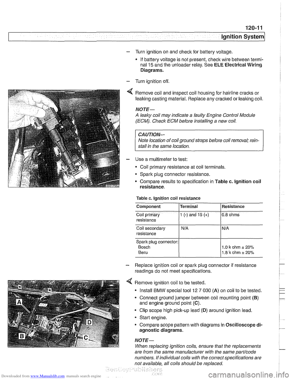
Remove coil and inspect coil housing for hairline
cracks or
leaking casting material. Replace any
cracked or leaking coil.
NOTE-
A leaky coil may indicate a faulty Engine Control Module
(ECM). Check ECM before installing a new coil.
CAUTION-
Note location of coilground straps before coil removal; rein-
stall in the same location.
Use a multimeter to test:
Coil primary resistance at coil terminals.
Sparlt plug connector resistance.
* Compare results to specification in Table c. lgnition coil
resistance.
Table c. Ignition coil resistance
Coil secondary
resistance
Spark plug connector:
Bosch 1 .O I( ohm t 20%
1.8 ir ohm t 20%
Component
Co~l prlmary
resistance
- Replace ignition coil or sparlt plug connector if resistance
readings do not meet specifications.
4 Remove ignition coil to be tested.
Install
BMW special tool 12 7 030 (A) on coil to be tested.
Connect ground jumper between coil mounting point
(B)
and engine ground point (C).
Clip scope high pick-up lead (D) around ignition lead.
Start engine.
Compare scope pattern with diagrams in Oscilloscope
di-
agnostic diagrams.
NOTE-
When replacing ignition coils, ensure that the replacements
Terminal
1 (-) and 15 (+)
are
from the same manufacturer with the same partlcode
numbers. If individual coils with the correct specifications are
not available. all coils should be
re~laced.
Resistance
0.8 ohms
Page 370 of 1002
Downloaded from www.Manualslib.com manuals search engine
.-. .
Battery, Starter, Alternator
Warnings and cautions
WARNING -
Wear goggles, rubber gloves, and a rubber apron when
working around the battery or battery acid (electrolyte).
Battery acid contains sulfuric acid and can cause skin
irritation and burning.
If acid is spilled on your skin or
clothing, flush the area at once with large quantities of
water. If electrolyte gets into your eyes, flush them with
large quantities of clean water for several minutes and
call a physician.
Batteries that are being charged or are fully charged
give off explosive hydrogen gas. Keep sparks and open
flames away. Do not
smoke.
CA UTIOI\C
Only use a digital multimeter when testing automotive elec-
trical components.
. If a repair procedure specifies disconnecting the bat-
tery, follow the instruction for safety reasons.
Prior to disconnecting the battery, read the battery dis-
connection cautions in
001 General Cautions and
Warnings.
Models with MS43 engine management: Allow at least
3 minutes to elapse after turning ignition ley to OFFpo-
sition before disconnecting battery. This willallow sum-
cient tinie to complete the DMJL (fuel tank pressure)
test
* Disconnecting the battery cables may erase fault codes
stored in ECM memory.
Always disconnect the negative
(-) battery cable first
and reconnect it last. Cover the battery post with an in-
sulating material whenever the cable is removed.
Do not disconnect battery, alternator or starter wires
while the engine is running.
0 Never reverse the battery cables. Even a momentary
wrong connection can damage the alternator or other
electrical components.
Do not depend on the color of insulation to tell battery
positive and negative cables apart. Label cables before
removing.
The slide-tilt sunroof may fail to function properly
after
disconnecting and reconnecting the battery. Reinitial-
ize sunroof as described in 540 Sunroof.
Page 373 of 1002
Downloaded from www.Manualslib.com manuals search engine
Battery, Starter, ~lternatorl
WARNING-
Always wear protective goggles and clothing when perform-
ing a load test.
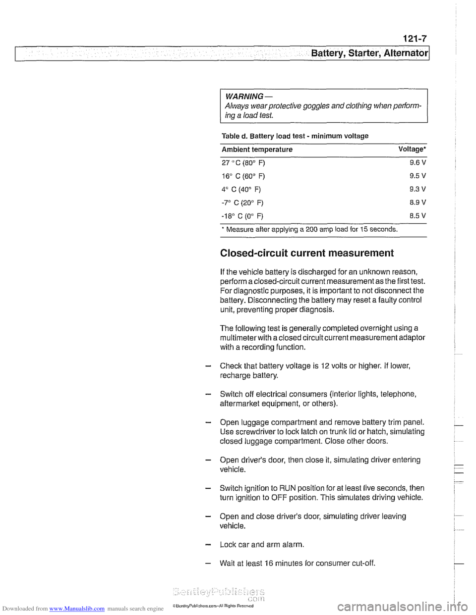
Table
d. Battery load test - minimum voltage
Ambient temperature Voltage*
27
" C (80" F) 9.6 V
-I 8' C (0"
F) 8.5 V
* Measure
after applying a 200 amp load for 15 seconds.
Closed-circuit current measurement
If the vehicle battery is discharged for an unknown reason,
perform a closed-circuit current measurement as the first test.
For diagnostic purposes, it is important to not disconnect the
battery. Disconnecting the battery may reset a faulty control
unit, preventing proper diagnosis.
The following test is generally completed overnight using a
multimeterwith a closed circuitcurrent measurement adaptor
with a recording function
- Check that battery voltage is 12 volts or higher. If lower,
recharge battery.
- Switch off electrical consumers (interior lights, telephone,
aftermarket equipment, or others).
- Open luggage compartment and remove battery trim panel.
Use screwdriver to lock latch on trunk lid or hatch, simulating
closed luggage compartment. Close other doors.
- Open driver's door, then close it, simulating driver entering
vehicle.
- Switch ignition to RUN position for at least five seconds, then
turn ignition to OFF position. This simulates driving vehicle.
- Open and close driver's door, simulating driver leaving
vehicle.
- Lock car and arm alarm.
- Wait at least 16 minutes for consumer cut-off.
Page 374 of 1002
Downloaded from www.Manualslib.com manuals search engine
121-8
/Battery, Starter, Alternator
NOTE-
Automatic transmission cars: ambershifier LED willgo out at
consumer cut-off.
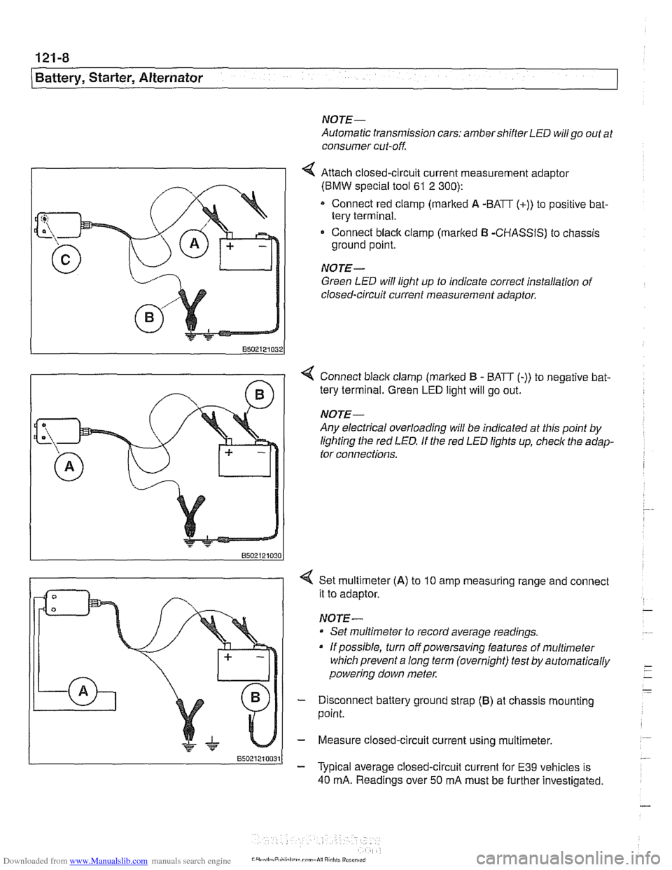
4 Attach closed-circuit current measurement adaptor
(BMW special tool
61 2 300):
Connect red clamp (marked A -BATT (+)) to positive bat-
tery terminal.
Connect
black clamp (marked B -CHASSIS) to chassis
ground point.
NOTE-
Green LED will light up to indicate correct installation of
closed-circuit current measurement
adaotor.
< Connect blaclc clamp (marked B - BATT (-)) to negative bat-
tery terminal. Green
LED light will go out.
NOTE-
Any electrical overloading will be indicated at this point by
lighting the red
LED. If the red LED lights up, check the adap-
tor connections.
< Set multimeter (A) to 10 amp measuring range and connect
it to adaptor.
NOTE -
Set multimeter to record average readings.
Ifpossible, turn offpowersaving features of multimeter
which prevent a long term (overnight) test by automatically
powering down
meter.
- Disconnect battery ground strap (B) at chassis mounting
point.
- Measure closed-circuit current using multimeter.
- Typical average closed-circuit current for E39 vehicles is
40 mA. Readings over 50 mA must be further investigated.
Page 378 of 1002
Downloaded from www.Manualslib.com manuals search engine
Battery, Starter, Alternator
Water-cooled alternator
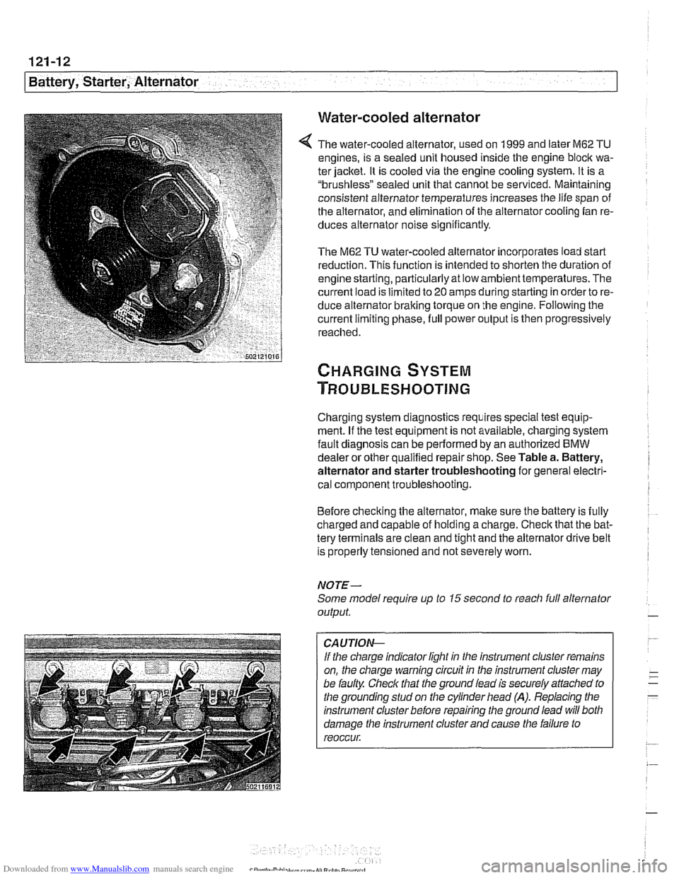
The water-cooled alternator, used on 1999 and later M62 TU
engines, is a sealed unit housed inside the engine block wa-
ter jacket. It is cooled via the engine cooling system. It is a
"brushless" sealed unit that cannot be serviced. Maintaining
consistent alternator temperatures increases the life span of
the alternator, and elimination of the alternator cooling fan re-
duces alternator noise
significantly.
The M62 TU water-cooled alternator incorporates load start
reduction. This function is intended to shorten the duration of
engine starting, particularly at low ambienttemperatures. The
current load is limited to
20 amps during starting in order to re-
duce alternator braking torque on the engine. Following the
current limiting phase, full power output is then progressively
reached.
Charging system diagnostics requires special test equip-
ment. If the test equipment is not available, charging system
fault diagnosis can be performed by an authorized
BMW
dealer or other qualified repair shop. See Table a. Battery,
alternator and starter troubleshooting for general electri-
cal component troubleshooting.
Before checking the alternator, make sure the battery is fully
charged and capable of holding a charge. Check that the bat-
tery terminals are clean and tight and the alternator drive belt
is properly tensioned and not severely worn.
NOTE-
Some model require up to 15 second to reacli full alternator
output.
CA UTIOG
If the charge indicator light in the instrument cluster remains
on, the charge warning circuit in the instrument cluster may
be faulty. Check that the ground lead is securely
affached to
the grounding stud on the cylinder head
(A). Replacing the
instrument cluster before repairing the ground lead will both
damage the instrument cluster and cause the failure to
reoccur.
Page 380 of 1002
Downloaded from www.Manualslib.com manuals search engine
- -
/Battery, Starter, Alternator -- - -. - --I
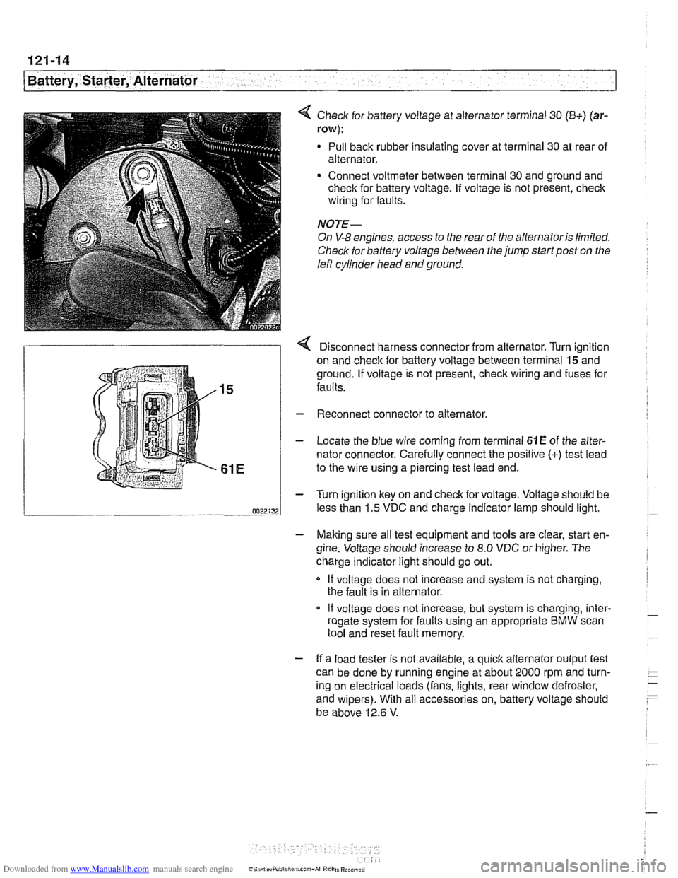
< Check for battery voltage at alternator terminal 30 (B+) (ar-
row):
Pull back rubber insulating cover at terminal 30 at rear of
alternator.
Connect voltmeter between terminal 30 and ground and
check for battery voltage.
If voltage is not present, check
wiring for faults.
NOTE-
On V-8 engines, access to the rear of the alternator is limited.
Check for battery voltage between the jump start post on the
left cylinder head and ground.
r Disconnect harness connector from alternator. Turn ianition
on and check for battery voltage between terminal
lgand
ground. If voltage is not present, check wiring and fuses for
faults.
Reconnect connector to alternator.
Locate the blue wire coming from terminal
61E of the alter-
nator connector. Carefully connect the positive
(+) test lead
to the wire using a piercing test lead end.
Turn ignition key on and check for voltage. Voltage should be
less than 1.5 VDC and charge indicator lamp should light.
- Making sure all test equipment and tools are clear, start en-
gine. Voltage should increase to
8.0 VDC or higher. The
charge indicator light should go out.
If voltage does not increase and system is not charging,
the fault is in alternator.
- If voltage does not increase, but system is charging, inter- - roaate svstem for faults usina an appropriate BMW scan - .. . tool and'reset fault memory.
- If a load tester is not available, a quick alternator output test
can be done by running engine at about 2000 rpm and turn-
- -
ing on electrical loads (fans, lights, rear window defroster, -
- and wipers). With all accessories on, battery voltage should
be above 12.6
V.