ECO BMW 525i 1997 E39 Workshop Manual
[x] Cancel search | Manufacturer: BMW, Model Year: 1997, Model line: 525i, Model: BMW 525i 1997 E39Pages: 1002
Page 408 of 1002
Downloaded from www.Manualslib.com manuals search engine
130-1 8
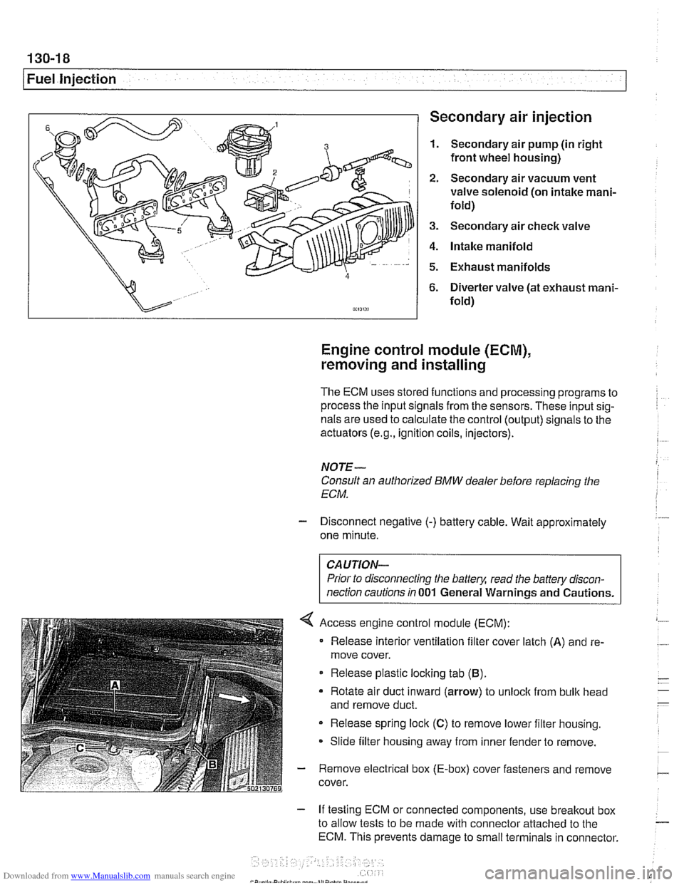
1 Fuel injection Secondary air injection
1. Secondary air pump (in right
front wheel housing)
2. Secondary air vacuum vent
valve solenoid (on intake mani-
fold)
3. Secondary air check valve
4. Intake manifold
5. Exhaust manifolds
6. Diverter valve (at exhaust mani-
fold)
Engine control module (ECM),
removing and installing
The ECM uses stored functions and processing programs to
process the input signals from the sensors. These input sig-
nals are used to calculate the control (output) signals to the
actuators
(e.g., ignition coils, injectors).
NOTE-
Consult an authorized BMW dealer before replacing the
ECM.
- Disconnect negative (-) battery cable. Wait approximately
one minute.
Prior to disconnecting the
battely, read the battery discon-
nection cautions in
001 General Warnings and Cautions.
Access engine control module (ECM):
Release interior ventilation filter cover latch
(A) and re-
move cover.
Release plastic locking tab
(B).
Rotate air duct inward (arrow) to unloclc from bulk head
and remove duct.
Release spring lock
(C) to remove lower filter housing.
Slide filter housing away from inner fender to remove.
- Remove electrical box (E-box) cover fasteners and remove
cover.
- If testing ECM or connected components, use breakout box
to allow tests to be made with connector attached to the
ECM. This prevents damage to small terminals in connector.
Page 409 of 1002
Downloaded from www.Manualslib.com manuals search engine
Fuel Injection I
- As an alternative, harness connector housing can be sepa-
rated so that electrical
checlts can be made from backof con-
nector.
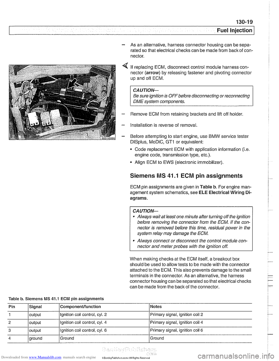
4 If replacing ECM, disconnect control module harness con-
nector (arrow) by releasing fastener and pivoting connector
up and
off ECM.
CAUTION-
Be sure ignition is OFF before disconnecting or reconnecting
DME system components.
- Remove ECM from retaining brackets and lift off holder.
- Installation is reverse of removal.
- Before attempting to start engine, use BMW service tester
DISplus, MoDiC, GTI or equivalent:
- Code replacement ECM with application information (i.e.
engine code, transmission type, etc.).
Align ECM to EWS (electronic immobilizer).
Siemens MS 41.1 ECM pin assignments
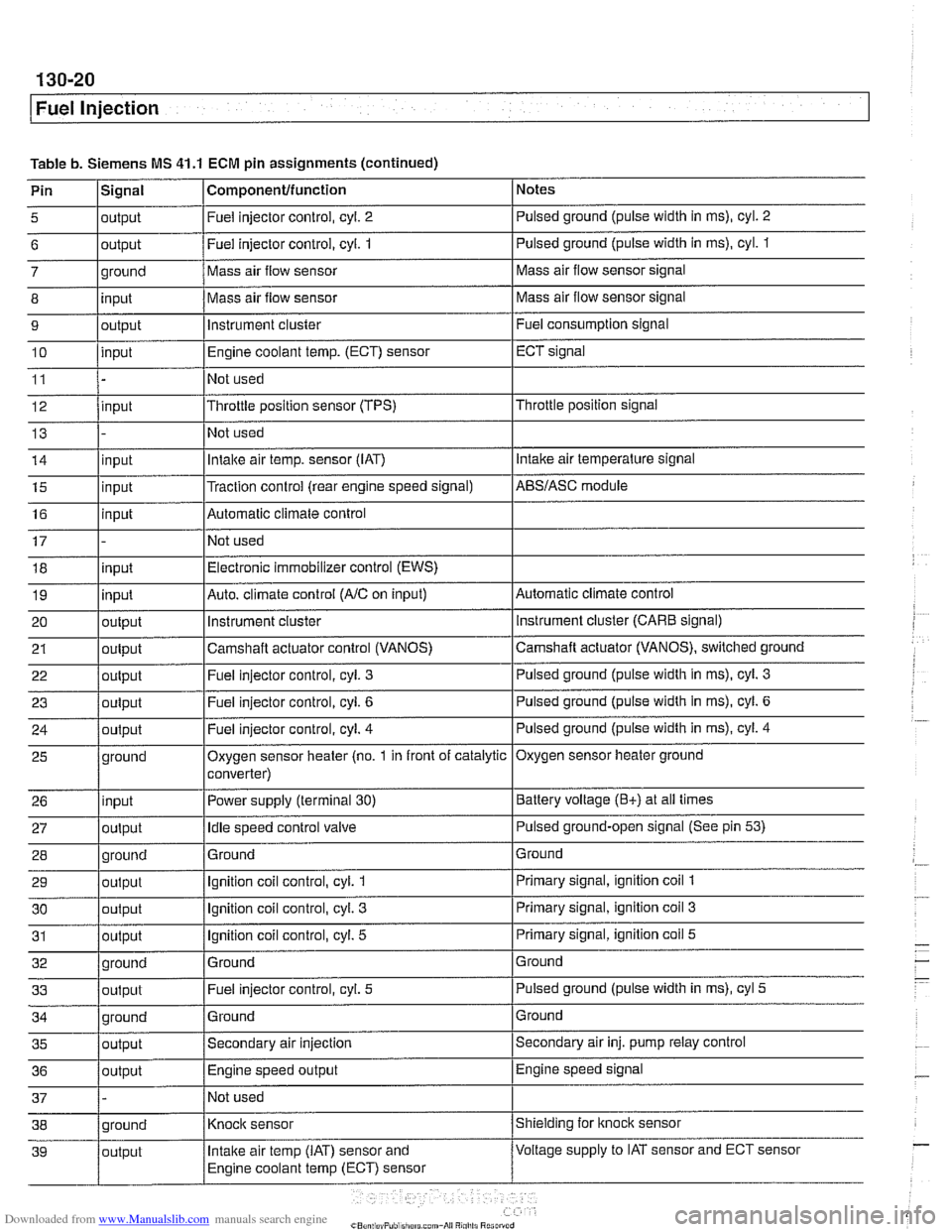
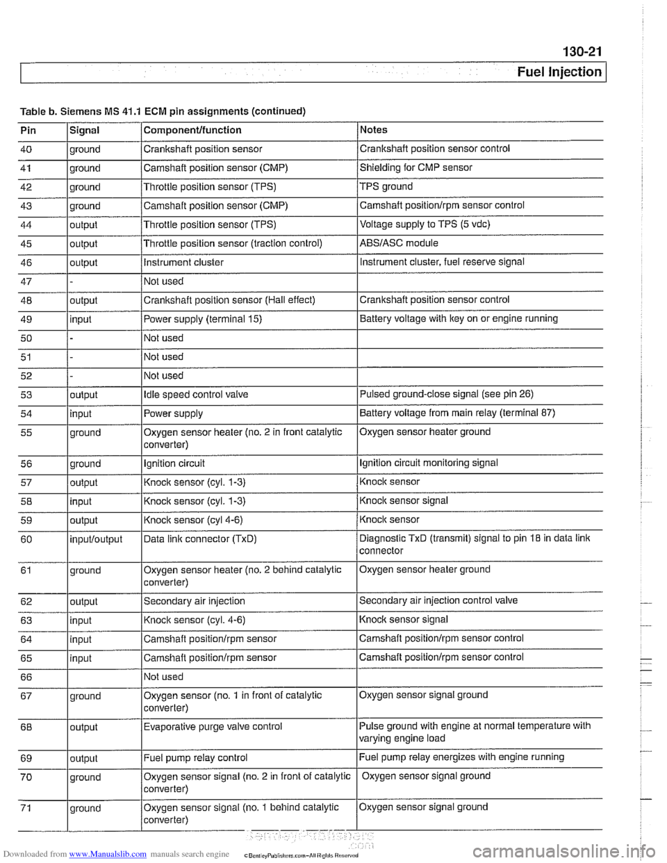
ECM pin assignments are given in Table b. For engine man-
agement system schematics, see ELE Electrical Wiring
Di-
agrams.
CAUTION-
a Always wait at least one minute after turning off the ignition
before removing the connector from the
ECM. If the con-
nector is removed before this time, residual power
in the
system relay may damage the
ECM.
Always connect or disconnect the control module con-
nector and meter probes with the ignition
off
When malting checks at the ECM itself, a breakout box
should be used to allow tests to be made with the connector
attached to the ECM. This also prevents damage to the small
terminals in the connector. As an alternative, the harness
connector housing can be separated so that electrical checlts
can be made from the back of the connector.
Table b. Siemens MS
41.1 ECM pin assignments
Pin
1
2
3
4
Signal
output
output
output
qround Componenfffunction
Ignition coil control, cyl. 2
Ignition coil control, cyl. 4
ignition coil control, cyl. 6
Ground Notes
Primary signal,
ignition
coil 2
Primary signal, ignition coil 4
Primary signal, ignition coil 6
Ground
Page 410 of 1002
Downloaded from www.Manualslib.com manuals search engine
I Fuel Injection
Table b. Siemens MS 41.1 ECM pin assignments (continued)
Pin
l~iqnal I Componentlfunction 1 Notes I - I I
5 loutput I Fuel injector control, cyl. 2 I Pulsed ground (pulse width in ms), cyl. 2 I I I
6 loutput /Fuel injector control, cyi. 1 I Pulsed ground (pulse width in ms), cyl. 1
I I I
14 linput I Intake air temp. sensor (IAT) I Intake air temperature signal
- 7
8
9
10
11
12
13
ground
input
output
input
input
15
16
17 18
19
20
21
22
I - I I
35 loutput /Secondary air injection ISecondary air inj. pump relay control
25
26
27
28
29
30
31
32
33
36
/output I Engine speed output IEngine speed signal
Mass air flow sensor
Mass air flow sensor
instrument cluster
Engine coolant
temp.
(ECT) sensor
Not used
Throttle position sensor (TPS)
Not used
input
input
input
input
output
output
out~ut
37 1 - /Not used I
Mass air flow sensor signal
Mass air flow sensor signal
Fuel consumption signal
ECT signal
Throttle position signal
ground
input
output
ground
output
output
output
ground
output
Traction control (rear engine speed signal) Automatic climate control
Not used Electronic immobilizer control (EWS)
Auto. climate control
(AIC on input)
instrument
cluster
Camshaft actuator control (VANOS)
Fuel iniector control, cvl.
3
AES/ASC module
Automatic climate control instrument cluster (CARE signal)
Camshaft actuator (VANOS), switched ground
Pulsed ground (pulse width in
ms), cyl. 3
Oxygen sensor heater (no. 1 in front of catalytic
converter)
Power supply (terminal
30)
Idle speed control valve
Ground
Ignition coil control, cyl.
1
Ignition coil control, cyl. 3
Ignition coil control, cyl. 5
Ground Fuel injector control, cyl.
5
Oxygen sensor heater ground
Battery voltage
(E+) at all times
Pulsed ground-open signal (See pin
53)
Ground
Primary signal, ignition coil
1
Primary signal, ignition coil 3
Primary signal, ignition coil 5
Ground
Pulsed ground (pulse width in ms), cyl
5
Page 411 of 1002
Downloaded from www.Manualslib.com manuals search engine
Fuel lniection 1
Table b. Siemens MS 41.1 ECM pin assignments (continued)
Pin
lSiqnal 1 Componentlfunction / Notes I - I I
40 1 ground /Crankshaft position sensor /crankshaft position sensor control I - I I
41 1 ground /Camshaft position sensor (CMP) /shielding for CMP sensor I - I I
42 1 ground I~hrottie position sensor (TPS) /TPS ground
43
44
45
46
47
48
49
50
51 ground
output
output
output
outout
I I I
input
52 53
54
55
56 57
58
59
60
61
62
63
64
65
66 Camshaft position sensor (CMP)
Throttle position sensor (TPS)
Throttle position sensor (traction control)
Instrument cluster
Not used
Crankshaft position sensor (Hall effect)
I~ot used
I I I
Fuel pump relay control Camshaft
positionlrpm sensor control
Voltage
supply to TPS (5 vdc)
ABSIASC module
Instrument cluster, fuel reserve signal
Crankshaft position sensor control
Power supply (terminal 15)
Not used
Not used
output input
ground
ground
output
input
output
inputloutput
ground
output
input
input
input
I I
Battery voltage with key on or engine running
Oxygen sensor signal ground
67
Idle speed control valve
Power supply
Oxygen sensor heater (no. 2 in front catalytic
converter)
Ignition circuit
Knock sensor
(cyl. 1-3)
Knock sensor (cyl. 1-3)
Knock sensor
(cyl4-6)
Data linic connector (TxD)
Oxygen sensor heater (no. 2 behind catalytic
converter)
Secondary air injection
Knock sensor (cyl. 4-6)
Camshaft
positionlrpm sensor
Camshaft
positionlrpm sensor
Not used
Pulse ground with engine at normal temperature with
varying engine load
68 Pulsed ground-close signal (see
pin 26)
Battery voltage from main relay (terminal 87)
Oxygen sensor heater ground
Ignition circuit monitoring signal
Knock sensor
Knock sensor signal
Knock sensor
Diagnostic
TxD (transmit) signal to pin 18 in data link
connector
Oxygen sensor heater ground
Secondary air injection control
valve
Knocic sensor signal
Camshaft positionlrpm sensor control
Camshaft
positionlrpm sensor control
ground Oxygen sensor
(no.
1 in front of catalytic
converter)
output Evaporative purge
valve control
Page 414 of 1002
Downloaded from www.Manualslib.com manuals search engine
Fuel Injection
- Ignition:
Direct ignition
Knock control
4 Primary1 secondary ignition monitoring
- Emissions:
OBD II compliance
Secondary air injection
Pre- and post-catalyst oxygen sensors
0 Electrically heated DME-mapped thermostat
Misfire detection
Evaporative emission control and
leak detection
Malfunction indicator light (MIL)
Performance controls:
Dual VANOS control
Output of injection signal (TI) for fuel economy gauge
Output of engine rpm (TD) for tachometer
AIC compressor control
0 Electric radiator cooling fan
CAN-Bus communication
Stability and traction system
(ABSIASCIDSC) interlace
Electronic immobilizer (EWS)
Cruise control
ECM programming
Page 415 of 1002
Downloaded from www.Manualslib.com manuals search engine
130-25
Fuel injection
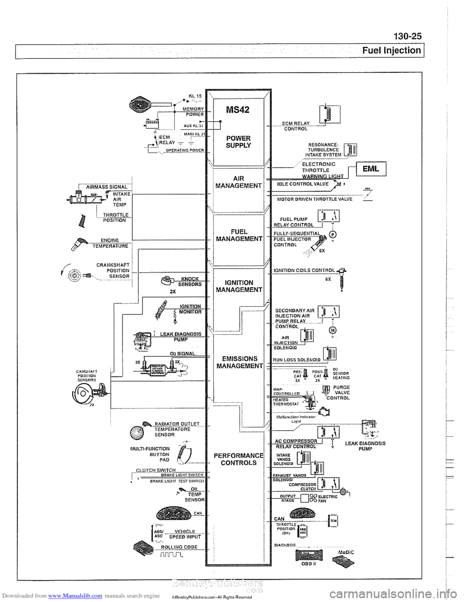
CONTROL RESONANCE.
TURBULENCE
----, VALVE
CRANUSHAFT
SECONDARY AIR
MULTI-FUNCTION ROLLING CODE
Page 419 of 1002
Downloaded from www.Manualslib.com manuals search engine
Fuel Injection
A faulty MAF sensor can produce the following problems:
Difficult to restart when engine is hot
Engine starts then stalls
* Engine starts and runs only with accelerator pedal de-
pressed
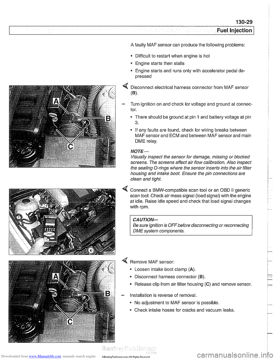
4 Disconnect electrical harness connector from MAF sensor
(B).
- Turn ignition on and checlc for voltage and ground at connec-
tor.
There should be ground at pin
1 and battery voltage at pin
3.
- If any faults are found, checlc for wiring breaks between
MAF sensor and ECM and between MAF sensor and main
DME relay.
NOTE-
Visually inspect the sensor for damage, missing or blocked
screens. The screens affect air flow calibration. Also inspect
the sealina
0-rinas where the sensor inserts into the air filter - - housing and intake boot. Ensure the pin connections are
clean and tight.
4 Connect a BMW-compatible scan tool or an OED II generic
scan tool.
Checlc air mass signal (load signal) with the engine
at idle. Raise idle speed and
checlc that load signal changes
with rpm.
CAUTION-
Be sure ignition is OFFbefore disconnecting or reconnecting
DME system components.
Remove MAF sensor:
Loosen intake boot clamp
(A).
Disconnect harness connector (6).
* Release clip from air filter housing (C) and remove sensor.
- Installation is reverse of removal.
No adjustment to MAF sensor is possible.
Check intake hoses for cracks and vacuum
lealts.
Page 420 of 1002
Downloaded from www.Manualslib.com manuals search engine
Fuel Injection
Engine coolant temperature
(ECT) sensor,
testing and replacing
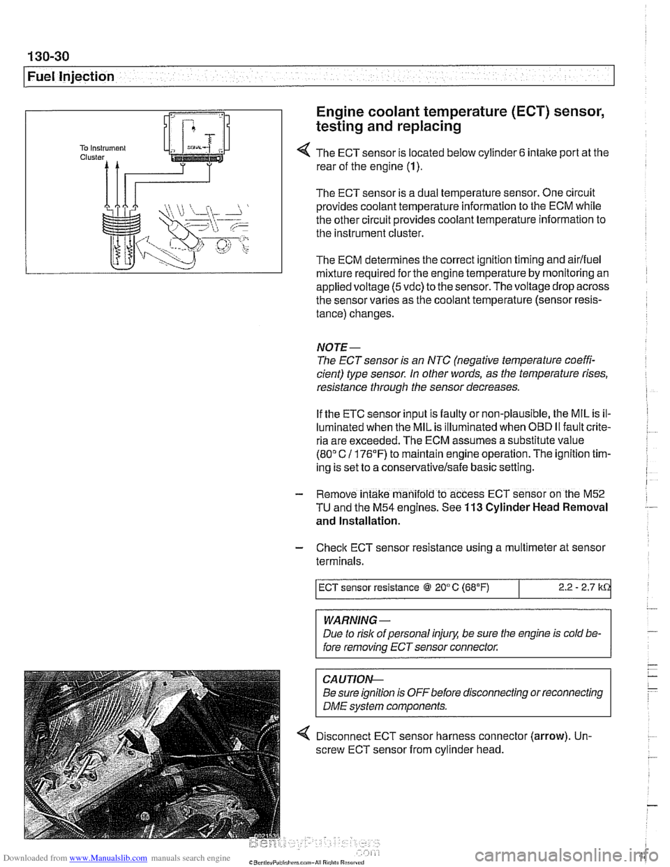
4 The ECT sensor is located below cylinder 6 intake port at the
rear of the engine (1).
The ECT sensor is a dual temperature sensor. One circuit
provides coolant temperature information to the ECM while
the other circuit provides coolant temperature information to
the instrument cluster.
The ECM determines the correct ignition timing and airlfuel
mixture required
forthe engine temperature by monitoring an
appliedvoltage
(5vdc) to the sensor.Thevoltage drop across
the sensor varies as the coolant temperature (sensor resis-
tance) changes.
NOTE-
The ECT sensor is an NTC (negative temperature coeffi-
cient) type sensor. In other words, as the temperature rises,
resistance through the sensor decreases.
If the ETC sensor input is faulty or non-plausible, the MIL is il-
luminated when the MIL is illuminated when
OED II fault crite-
ria are exceeded. The ECM assumes a substitute value
(80" C 11 76'F) to maintain engine operation. The ignition tim-
ing is set to a
conservativelsafe basic setting.
- Remove intake manifold to access ECT sensor on the M52
TU and the M54 engines. See 113 Cylinder Head Removal
and Installation.
- Check ECT sensor resistance using a multimeter at sensor
terminals.
WARNING -
Due to rislc of personal injury, be sure the engine is cold be-
fore removing ECT sensor connector.
ECT sensor resistance @ 20°C (68°F)
CAUTIOI\C
Be sure ignition is OFFbefore disconnecting or reconnecting
DME svstem components.
2.2 - 2.7 k
4 Disconnect ECT sensor harness connector (arrow). Un-
screw ECT sensor from cylinder head.
Page 428 of 1002
Downloaded from www.Manualslib.com manuals search engine
130-38
Fuel Injection
Throttle cable, adjusting
(MS 42.0)
The throttle assembly on MS 42.0 cars uses a throttle cable.
The cable should be adjusted any time it is disconnected or
replaced. This procedure requires the factory scan tool or an
equivalent to read and adjust throttle angle. It is recommend-
ed the procedure be done by an authorized
BMW dealer ser-
vice department
Basic adjustment:
Ensure that at idle (accelerator pedal in rest position) throt-
tle cable has detectable play at throttle lever attaching
point. Play must not exceed maximum allowable.
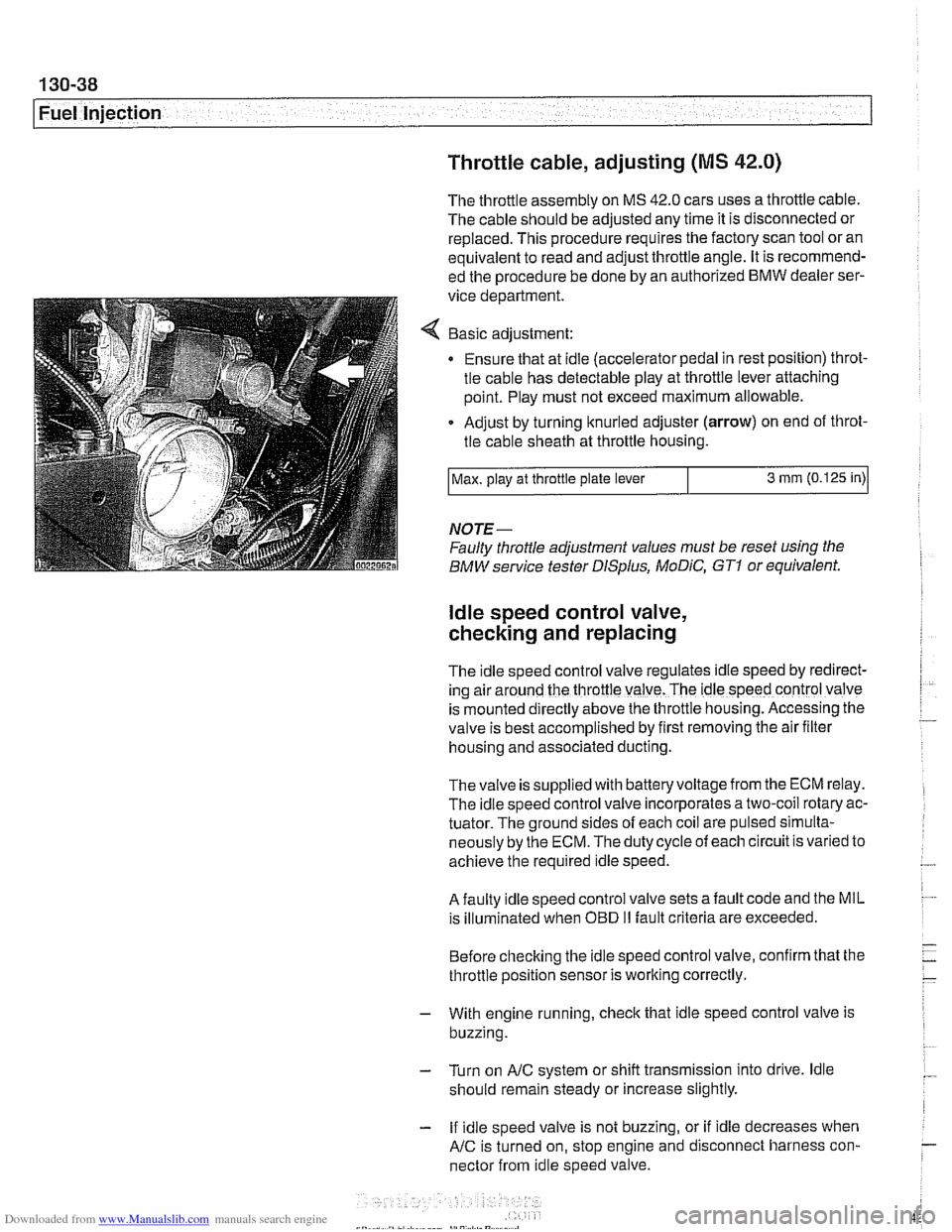
Adjust by turning knurled adjuster
(arrow) on end of throt-
tle cable sheath at throttle housing.
NOTE-
Faulty throttle adjustment values must be reset using the
BMW service tester
DISplus, MoDiC, GTI or equivalent.
Max.
play at throttle plate lever
ldle speed control valve,
checking and replacing
3 mm (0.125 in)
The Idle speed control valve regulates Idle speed by red~rect-
ing air around the throttle valve. The ldle speed control valve
is mounted
d~rectly above the throttle housing. Accessing the
valve is best accomplished by
flrst removing the air fllter
housing and associated ducting.
Thevalve is supplied with batteryvoltage from the ECM relay.
The idle speed control valve incorporates a two-coil rotary ac-
tuator. The ground sides of each coil are pulsed simulta-
neously by the ECM. The duty cycle of each circuit is varied to
achieve the required idle speed.
A faulty idle speed control valve sets a fault code and the MIL
is illuminated when
OED II fault criteria are exceeded.
Before checking the idle speed control valve, confirm that the
throttle position sensor is working correctly.
- With engine running, check that idle speed control valve is
buzzing.
- Turn on AIC system or shift transmission into drive. ldle
should remain steady or increase slightly.
- If idle speed valve is not buzzing, or if idle decreases when
AIC is turned on, stop engine and disconnect harness con-
nector from idle speed valve.
Page 429 of 1002
Downloaded from www.Manualslib.com manuals search engine
. .
Fuel Injection
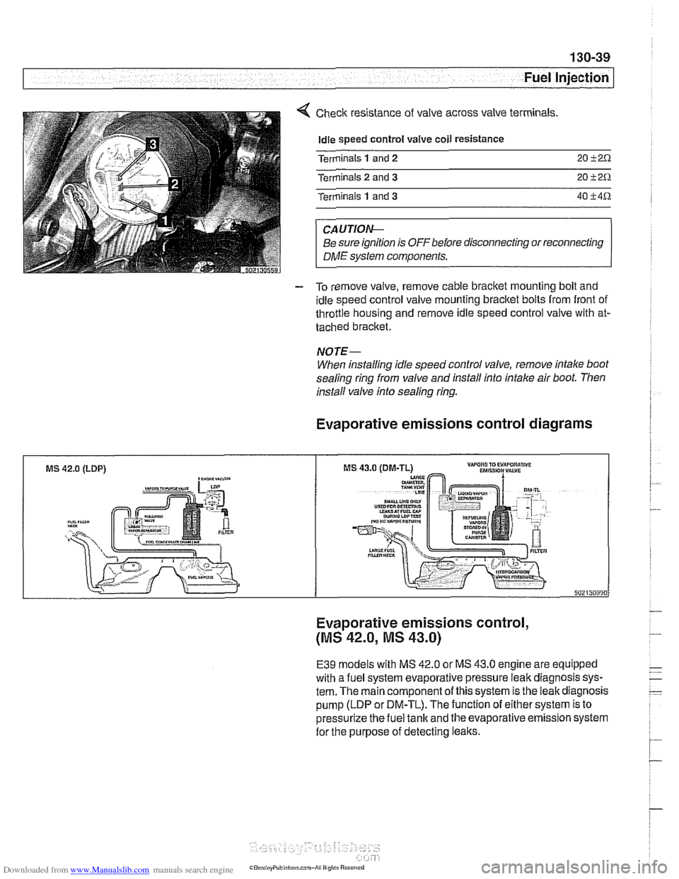
Check resistance of valve across valve terminals
Idle speed control valve coil resistance
Terminals
1 and 2 20 i2.0.
Terminals 2 and 3 20 i2.0.
Terminals 1 and 3 40 i4.0.
CAUTIOIG
Be sure ignition is OFFbefore disconnecting or reconnecting
DME system components.
- To remove valve, remove cable bracket mounting bolt and
idle speed control valve mounting bracket bolts from front of
throttle housing and remove idle speed control valve with at-
tached bracket.
NOTE-
When installing idle speed control valve, remove intake boot
sealing ring from valve and install into intake air boot. Then
install valve info sealing
ring.
Evaporative emissions control diagrams
MS 42.0 (LDP) ,-a"-
Evaporative emissions control,
(MS 42.0, MS 43.0)
E39 models with MS 42.0 or MS 43.0 engine are equipped
with a fuel system evaporative pressure leak diagnosis sys-
tem. The main component of this system is the leak diagnosis
pump (LDP or DM-TL). The function of either system is to
pressurize the fuel tank and the evaporative emission system
for the purpose of detecting leaks.