rear BMW 525i 1997 E39 Owner's Manual
[x] Cancel search | Manufacturer: BMW, Model Year: 1997, Model line: 525i, Model: BMW 525i 1997 E39Pages: 1002
Page 112 of 1002
Downloaded from www.Manualslib.com manuals search engine
I Cylinder Head Removal and Installation
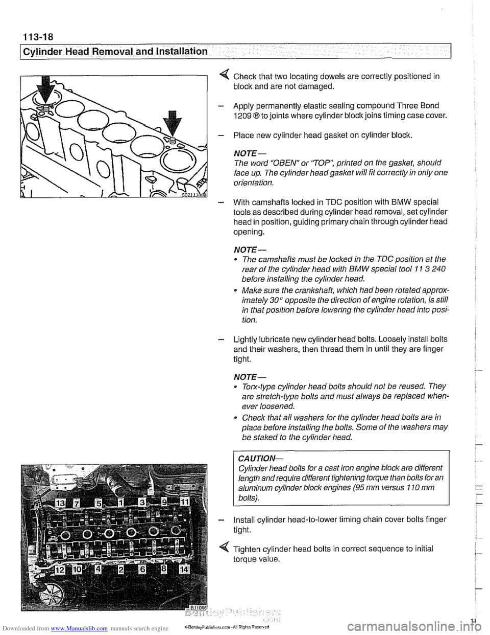
4 Check that two locating dowels are correctly positioned in
block and are not damaged.
- Apply permanently elastic sealing compound Three Bond
1209 8 to joints where cylinder block joins timing case cover.
- Place new cylinder head gasket on cylinder block.
NOTE-
The word "OBEN" or 'TOP': printed on the gasket, should
face up. The cylinder head
gasket will fit correctly in only one
orientation.
- With camshafts locked in TDC oosition with BMW soecial
tools as described during cylinder head removal,
seicylinder
head in position, guiding primary chain through cylinder head
opening.
NOTE-
* The camshafts must be locl(ed in the TDC position at the
rear of the cylinder head with
BMW special tool I1 3 240
before installing the cylinder head.
Make sure the
cranksha% which had been rotated approx-
imately
30" opposite the direction of engine rotation, is still
in that position before lowering the cylinder head into posi-
tion.
- Lightly lubricate new cylinder head bolts. Loosely install bolts
and their washers, then thread them in until they are finger
tight.
NOTE-
. Torx-type cylinder head bolts should not be reused. They
are stretch-type bolts and must always be replaced when-
ever loosened.
Check that all washers for the cylinder head bolts are in
place before installing the bolts. Some of the washers may
be
stalced to the cylinder head.
CAUTIOI\C
Cylinder head bolts for a cast iron engine block are different
length and require different tightening torque than bolts for an
aluminum cylinder bloclc engines
(95 rnm versus 110 rnm
bolts).
- Install cylinder head-to-lower timing chain cover bolts finger
tight.
< Tighten cylinder head bolts in correct sequence to initial
torque value.
Page 116 of 1002
Downloaded from www.Manualslib.com manuals search engine
1 13-22
Cylinder Head Removal and Installation
CYLINDER HEAD REMOVAL AND
~NSTALLATION (M52 TU AND N154
ENGINES)
WARNING -
Due to risk ofpersonal injur)c be sure the engine is cold be-
fore
beqinning the removal procedure.
Cylinder head removal and installation is a time consuming
repair procedure requiring multiple special service tools.
Read the entire procedure before beginning the repair.
This topic includes the following procedures:
* Cylinder head, removing, M52 TU and M54 engines
Cylinder head, installing,
M52 TU and M54 engines
Cylinder head, removing,
M52 TU and M54 engines
Allow engine to cool before beginning this procedure.
- Disconnect negative (-) cable from battery.
CAUTION-
Prior to disconnecting the battery, read the battery discon-
nection cautions in
001 General Cautions and Warnings.
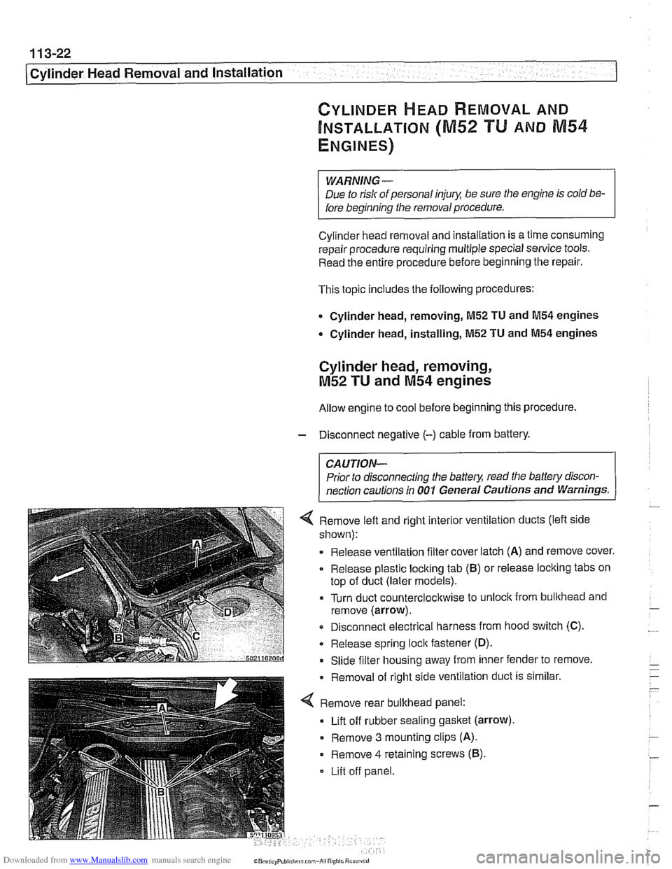
4 Remove left and right interior ventilation ducts (left side
shown):
Release ventilation filter cover latch
(A) and remove cover.
Release plastic locking tab
(6) or release locking tabs on
top of duct (later models).
= Turn duct counterclocltwise to unlock from bullthead and
remove (arrow).
Disconnect electrical harness from hood switch (C).
Release spring lock fastener
(D).
- Slide filter housing away from inner fender to remove.
Removal of right side ventilation
dud
Remove rear bulkhead panel:
Lift off rubber sealing
gasket (arrow)
- Remove 3 mounting clips (A).
Remove 4 retaining screws (6).
Lift off panel.
: is similar
Page 117 of 1002
Downloaded from www.Manualslib.com manuals search engine
- --
Cylinder Head Removal and Installation 1 --
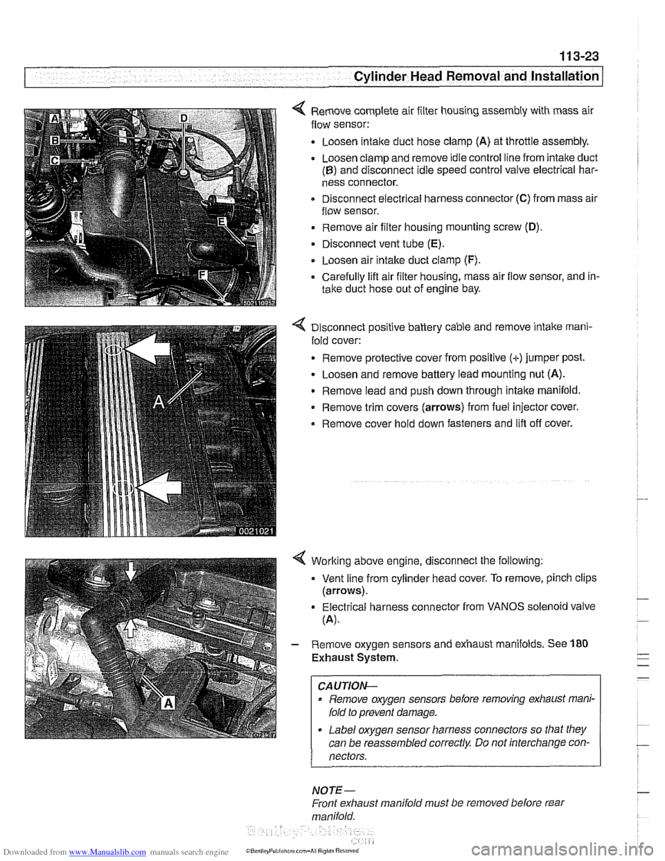
< Remove complete air filter housing assembly with mass air
flow sensor:
Loosen
intalte duct hose clamp (A) at throttle assembly.
Loosen clamp and remove idle control line from intake duct
(B) and disconnect idle speed control valve electrical har-
ness connector.
Disconnect electrical harness connector
(C) from mass air
flow sensor.
Remove air filter housing mounting screw
(D).
Disconnect vent tube (E).
. Loosen air intalte duct clamp (F).
Carefully lifl air filter housing, mass air flow sensor, and in-
take duct hose out of engine bay.
4 Disconnect positive battery cable and remove intake rnani-
fold cover:
Remove protective cover from positive (+)jumper post.
Loosen and remove battery lead mounting nut (A).
Remove lead and push down through intake manifold.
* Remove trim covers (arrows) from fuel injector cover.
Remove cover hold down fasteners and lifl off cover.
4 Worlting above engine, disconnect the following:
Vent line from cylinder head cover. To remove, pinch clips
(arrows).
Electrical harness connector from VANOS solenoid valve
(A).
- Remove oxygen sensors and exhaust manifolds. See 180
Exhaust System.
CAUTION-
Remove oxygen sensors before removing exhaust mani-
fold to prevent damage.
Label oxygen sensor harness connectors so that they
can be reassembled correctly Do not interchange con-
nectors.
NOTE-
Front exhaust manifold must be removed before rear
manifold.
Page 121 of 1002
Downloaded from www.Manualslib.com manuals search engine
11 3-27
Cylinder Head Removal and Installation
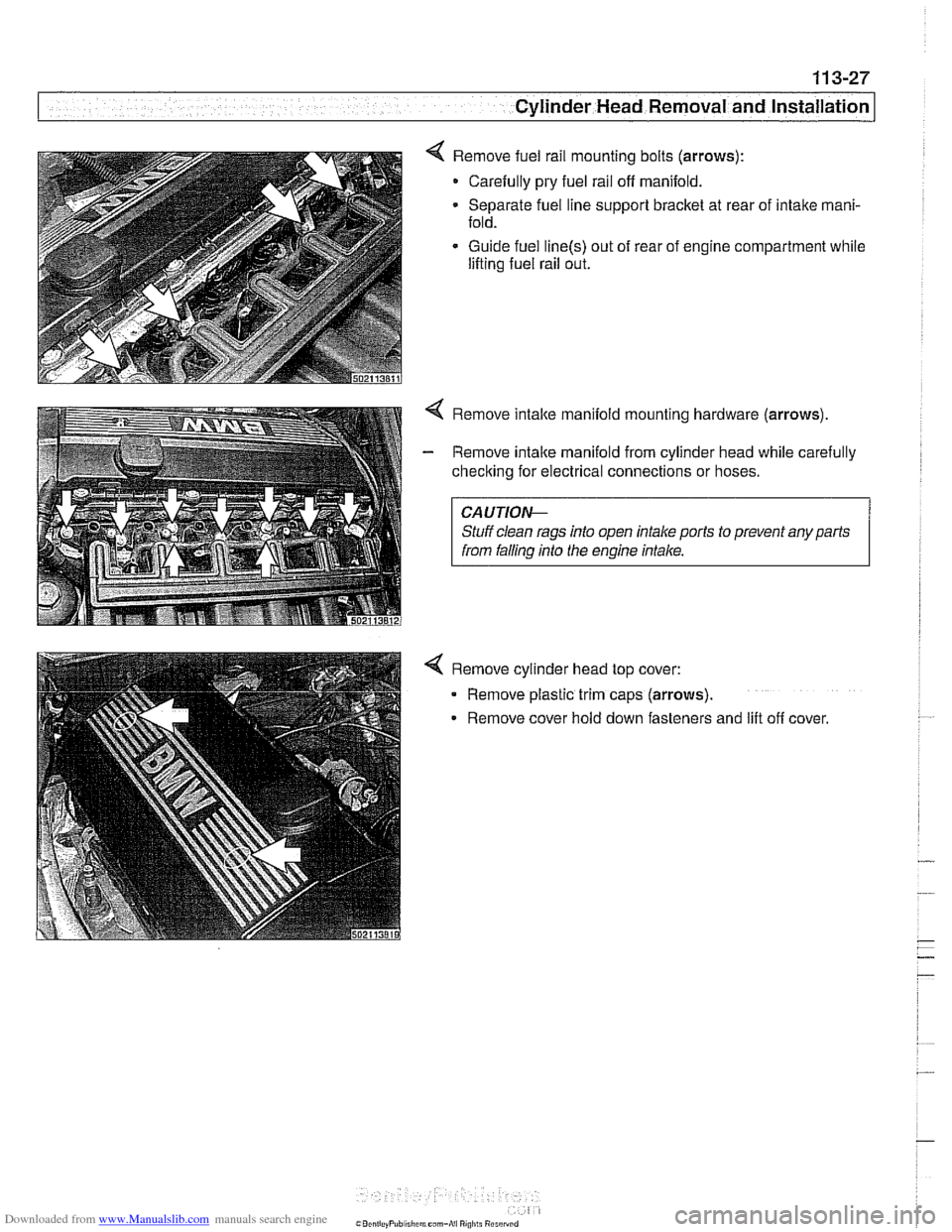
< Remove fuel rail mounting bolts (arrows):
- Carefully pry fuel rail off manifold.
Separate fuel line support bracket at rear of intake mani-
fold.
Guide fuel
line(s) out of rear of engine compartment while
lifting fuel rail out.
4 Remove intake manifold mountino hardware (arrows).
I from falling into the engine intake. I
4 Remove cylinder head top cover:
- Remove plastic trim caps (arrows).
Remove cover hold down fasteners and
lilt off cover.
Page 125 of 1002
Downloaded from www.Manualslib.com manuals search engine
11 3-31
Cylinder Head Removal and Installation
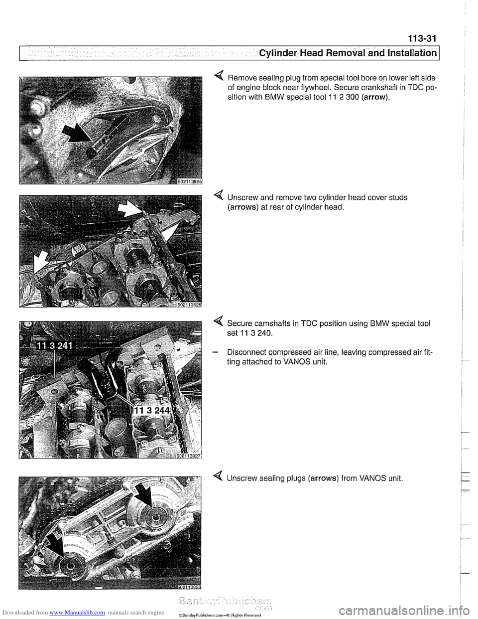
Remove sealing plug from special tool bore on lower left side
of engine block near flywheel. Secure crankshaft in TDC po-
sition with
BMW special tool l l 2 300 (arrow).
4 Unscrew and remove two cylinder head cover studs
(arrows) at rear of cylinder head.
4 Secure camshafts in TDC position using BMW special tool
set
11 3 240.
- Disconnect compressed air line, leaving compressed air fit
ting attached to VANOS unit.
4 Unscrew sealing plugs (arrows) from VANOS unit.
Page 131 of 1002
Downloaded from www.Manualslib.com manuals search engine
Cylinder Head Removal and Installation I
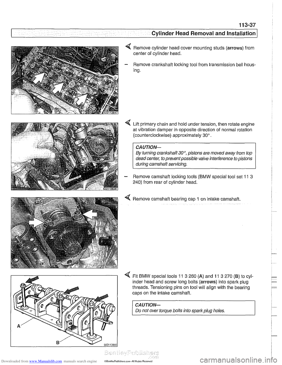
Remove cylinder head cover mounting studs (arrows) from
center of cylinder head.
- Remove crankshaft loclting tool from transmission bell hous-
Ing.
Lift primary chain and hold under tension, then rotate engine
at vibration damper in opposite direction of normal rotation
(counterclocltwise) approximately 30".
CAUTION-
By turning crankshait3O0, pistons are movedaway from top
dead center, to prevent possible valve interference to pistons
during camshaft servicing.
- Remove camshaft loclting tools (BMW special tool set 11 3
240) from rear of cylinder head.
4 Remove camshaft bearing cap 1 on intake camshaft.
4 Fit BMW special tools 11 3 260 (A) and 11 3 270 (B) to cyl-
inder head and screw long bolts (arrows) into spark plug
threads. Tensioning pins on tool will align with the bearing
caps on the
intake camshaft.
CAUJION-
Do not over torque bolts into sparkplug holes.
Page 154 of 1002
Downloaded from www.Manualslib.com manuals search engine
1 13-60
Cylinder Head Removal and Installation
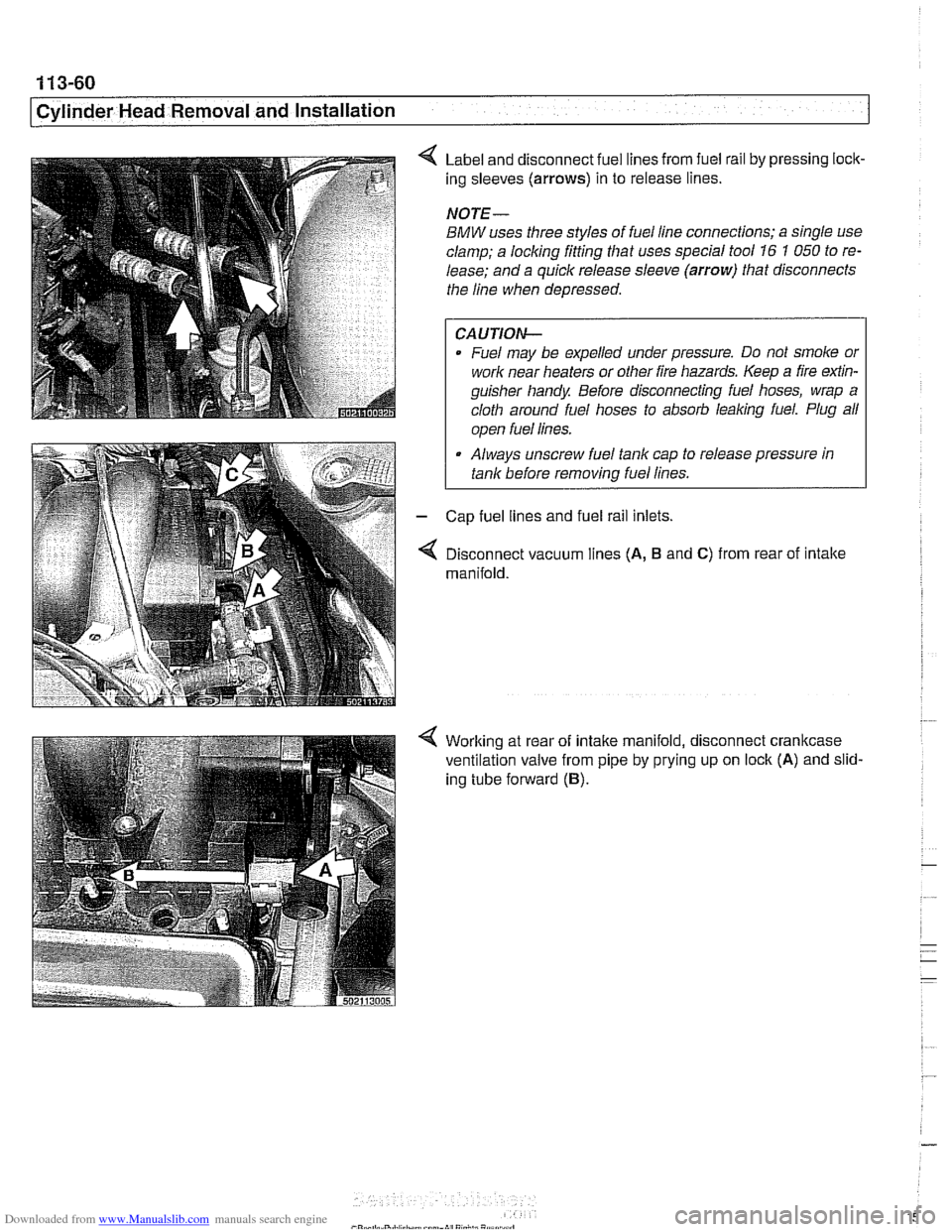
Label and disconnect fuel lines from fuel rail by pressing lock-
ing sleeves
(arrows) in to release lines.
NOTE-
BMW uses three styles of fuel line connections; a single use
clamp; a locking fitting that uses special tool
16 1 050 to re-
lease; and a quick release sleeve
(arrow) that disconnects
the line when depressed.
CAUTION-
Fuel may be expelled under pressure. Do not smoke or
work near heaters or other fire hazards. Keep a fire
exfin-
guisher handy Before disconnecting fuel hoses, wrap a
cloth around fuel hoses to absorb
leaking fuel. Plug all
I ooen fuel lines. I
Always unscrew fuel tank cap to release pressure in
tank before
removinq fuel lines.
Cap fuel lines and fuel rail inlets.
Disconnect vacuum lines
(A, B and C) from rear of intake
manifold.
Working at rear of intake manifold, disconnect crankcase
ventilation valve from pipe by prying up on lock
(A) and slid-
ing tube forward
(B).
Page 163 of 1002
Downloaded from www.Manualslib.com manuals search engine
11 3-69
Cylinder Head Removal and Installation
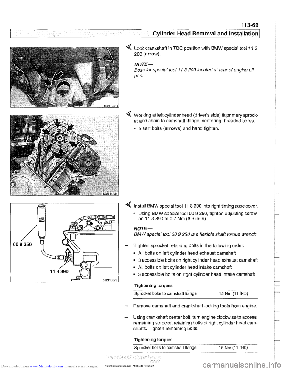
4 Lock crankshaft in TDC position with BMW special tool 11 3
200 (arrow).
NOTE-
Boss for special tool 11 3 200 located at rear of engine oil
pan.
4 Working at left cylinder head (driver's side) fit primary sprock-
et and chain to camshaft flange, centering threaded bores.
Insert bolts (arrows) and hand tighten.
?-I I 4 Install BMW special tool 11 3 390 into right timing case cover.
NOTE-
BMW special tool 00 9 250 is a flexible shaft torque wrench.
I - Tighten sprocket retaining bolts in the following order:
All bolts on left cylinder head exhaust camshaft
3 accessible bolts on right cylinder head exhaust camshaft
All bolts on left cylinder head
intake camshaft
3 accessible bolts on right cylinder head intake camshaft r"".."..7n
Tightening torques
Sprocltet bolts to camshait flange
15 Nm (11 ft-lb)
- Remove camshaft and crankshaft locking tools from engine.
- Using crankshaft center bolt, turn engine clockwise to access
remaining sprocket retaining bolts of right cylinder head cam-
shafts. Tighten remaining bolts.
Tightening torques Sprocket bolts to camshaft flange 15 Nm
(11 ft-lb)
Page 173 of 1002
Downloaded from www.Manualslib.com manuals search engine
-8" ."
Cylinder Head Removal and Installation --
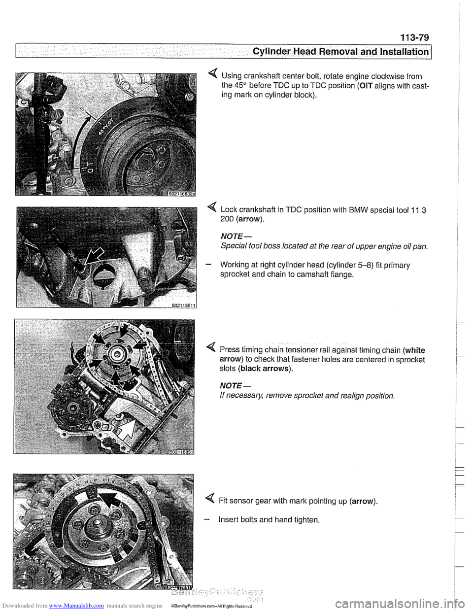
Using crankshaft center bolt, rotate engine clockwise from
the
45" before TDC up to TDC position (OIT aligns with cast-
ing mark on cylinder block).
< Lock crankshaft in TDC position with BMW special tool 11 3
200 (arrow).
NOTE-
Special tool boss located at the rear of upper engine oil pan.
- Working at right cylinder head (cylinder 5-8) fit primary
sprocltet and chain to camshaft flange.
!
I
4 Press timing chain tensioner rail against timing chain (white
arrow) to check that fastener holes are centered in sprocket
slots (black arrows).
NOTE-
If necessary, remove sprocl
Insert bolts and hand tighten.
Page 187 of 1002
Downloaded from www.Manualslib.com manuals search engine
Cylinder Head and Valvetrain
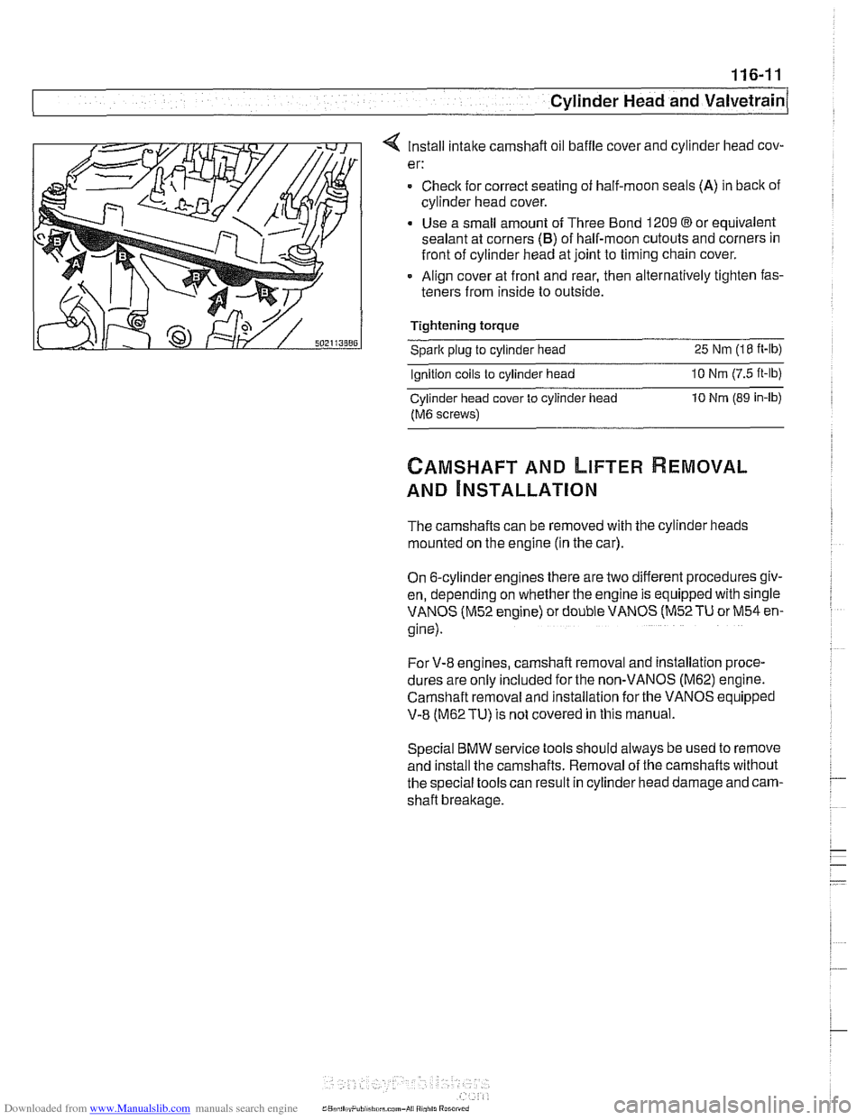
4 Install intake camshaft oil baffle cover and cylinder head cov-
er:
= Checlc for correct seating of half-moon seals (A) in back of
cylinder head cover.
Use a small amount of Three Bond 1209
@or equivalent
sealant at corners
(B) of half-moon cutouts and corners in
front of cylinder head at joint to timing chain cover.
Align cover at front and rear, then alternatively tighten fas-
teners from inside to outside.
Tightening torque
Sparic plug to cylinder head 25 Nm (18 it-lb)
Ignition coils to cylinder head 10 Nrn (7.5 ft-lb)
Cylinder head cover to cylinder iiead 10 Nrn (89 in-lb)
fM6 screws)
CAMSHAFT AND LIFTER REMOVAL
AND ~NSTALLATION
The camshafts can be removed with the cylinder heads
mounted on the engine (in the car).
On 6-cylinder engines there are two different procedures giv-
en, depending on whether the engine is equipped with single
VANOS (M52 engine) or double VANOS
(M52TU or M54 en-
gine).
For V-8 engines, camshaft removal and installation proce-
dures are
only included for the non-VANOS (M62) engine.
Camshaft removal and installation for the
VANOS eq;ipped
V-8 (M62TU) is not covered in this manual.
Special BMW service tools should always be used to remove
and install the camshafts. Removal of the camshafts without
the special tools can result in cylinder head damage and cam-
shaft breakage.