rear BMW 525i 1997 E39 Service Manual
[x] Cancel search | Manufacturer: BMW, Model Year: 1997, Model line: 525i, Model: BMW 525i 1997 E39Pages: 1002
Page 281 of 1002
Downloaded from www.Manualslib.com manuals search engine
Camshaft Timing chain1
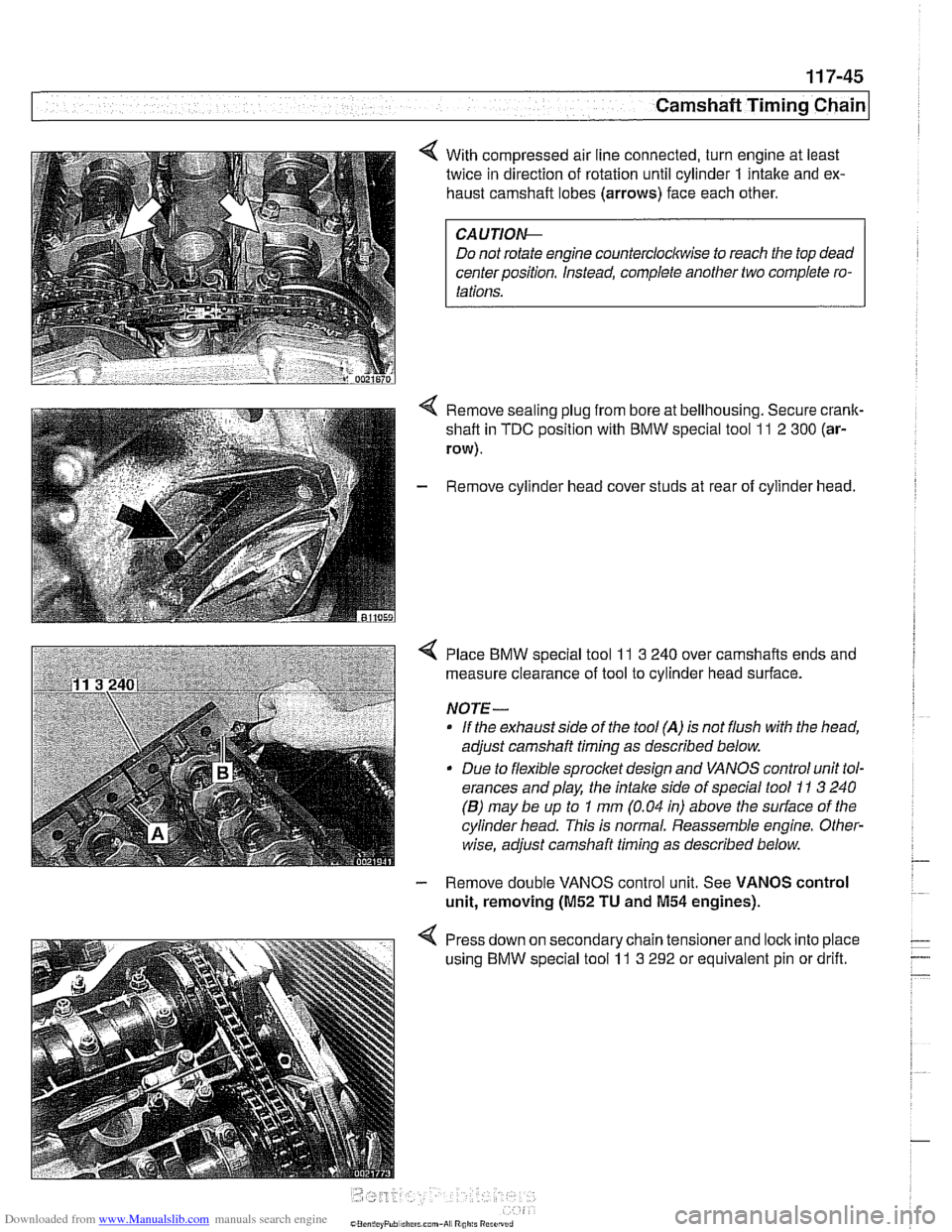
< With compressed air line connected, turn engine at least
twice in direction of rotation until cylinder
1 intake and ex-
haust camshaft lobes (arrows) face each other.
Do not rotate engine counterclockwise to reach the top dead
center position. Instead, complete another two complete ro-
Remove sealing plug from bore at bellhousing. Secure crank-
shaft in
TDC position with BMW special tool 11 2 300 (ar-
row).
- Remove cylinder head cover studs at rear of cylinder head.
< Place BMW special tool 11 3 240 over camshafts ends and
measure clearance of tool to cylinder head surface.
NOTE-
If the exhaust side of the tool (A) is not flush with the head,
adjust camshaft timing as described below.
Due to flexible sprocket design and VANOS control unit tol-
erances and play, the
intake side of special tool 11 3 240
(B) may be up to 1 mm (0.04 in) above the surface of the
cylinder head. This is normal. Reassemble engine. Other-
wise, adjust camshaft timing as described below.
- Remove double VANOS control unit. See VANOS control
unit, removing
(M52 TU and M54 engines).
< Press down on secondary chain tensionerand lock into place
using BMW special tool
11 3 292 or equivalent pin or drift.
Page 284 of 1002
Downloaded from www.Manualslib.com manuals search engine
-
I Camshaft Timing Chain - --
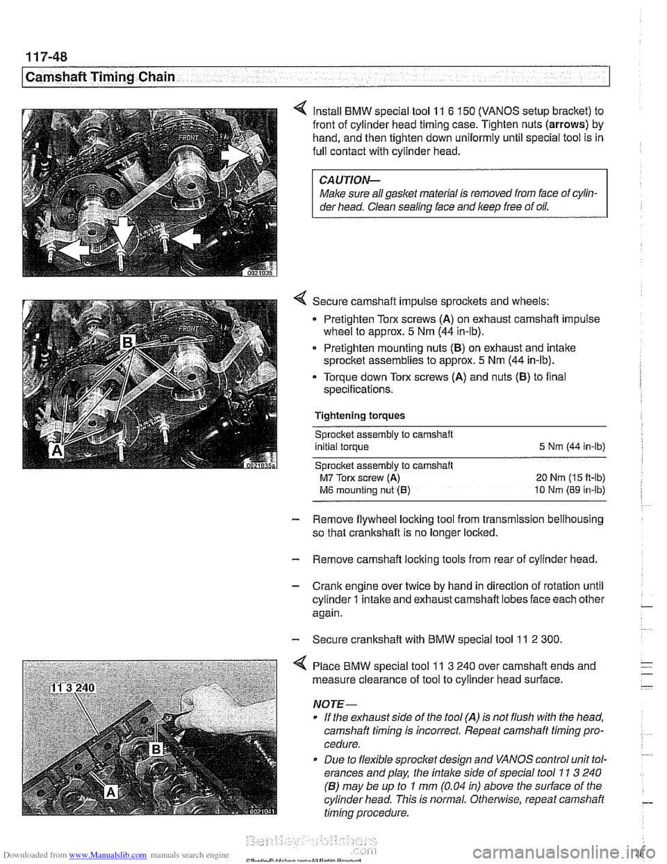
Install BMW special tool 11 6 150 (VANOS setup bracket) to
front of cylinder head timing case. Tighten nuts
(arrows) by
hand, and then tighten down uniformly until special tool is in
full contact with cylinder head.
CAUTION-
Male sure all gasket material is removed from face of cylin-
der head. Clean
sealins face and keep free of oil.
Secure camshaft impulse sprockets and wheels:
Pretighten Torx screws
(A) on exhaust camshaft impulse
wheel to approx.
5 Nm (44 in-lb).
Pretighten mounting nuts
(B) on exhaust and intake
sprocket assemblies to approx.
5 Nm (44 in-lb).
- Torque down Torx screws (A) and nuts (8) to flnal
specifications.
Tightening torques Sprocket assembly
to camshaft
initial torque
5 Nm (44 in-lb)
Sprocket assembly to camshaft
M7 Torx screw (A) 20 Nm (15 fl-lb)
ivl6 mounting nut (B) 10 tdm (89 in-lb)
- Remove flywheel locking tool from transmission bellhousing
so that crankshaft is no longer locked.
- Remove camshaft locking tools from rear of cylinder head.
- Crank engine over twice by hand in direction of rotation until
cylinder
1 intake and exhaust camshaft lobes face each other - again.
- Secure crankshaft with BMW special tool 11 2 300.
4 Place BMW special tool 11 3 240 over camshaft ends and
measure clearance of tool to cylinder head surface.
NOJE-
If the exhaust side of the tool (A) is not flush with the head,
camshaft timing
Is incorrect. Repeat camshaft timing pro-
cedure.
* Due to flexible sprocket design and VANOS control unit tol-
erances and play, the
intake side of special tool 11 3 240
(6) may be up to 1 mm (0.04 in) above the sudace of the
cylinder head. This is normal. Otherwise, repeat camshaft
timing procedure.
Page 285 of 1002
Downloaded from www.Manualslib.com manuals search engine
-- - -- - -- Camshaft Timing chain1
- Remove camshaft locking tools from rear of camshafts
- Remove BMW special tool 11 4 220 (adjustable primary
chain tensioner). Reinstall primary chain tensioner.
Tightening torque Primary chain tensioner to cylinder head
70
Nm (52 it-lb)
- Remove crankshaft locking tool from transmission bellhous-
ing. Reinstall sealing plug.
- Remove VANOS setup bracket from front of cylinder head
- lnstall VANOS control unit as described earlier in this group.
- Remove compressed air fitting (BMW special tool 11 3 450)
from VANOS control unit.
- Fit VANOS oil line banjo bolt with new seals. Attach oil line to
VANOS control unit.
Tightening torque
Oil line to VANOS control unit (banjo bolt) 32 Nm (24 H-lb)
- Remainder of installation is reverse of removal, noting the fol-
lowing:
lnstall spark plugs.
* lnstall intake camshaft plastic baffle prior to installing cylin-
der head cover. lnstall ignition coil packs and connect elec-
trical harness connectors.
Install radiator cooling fan.
- lnstall air filter housing and top engine cover.
Tightening torque Radiator cooling fan
(VISCOUS clutch) to 40 Nm (30 ft-lb)
coolant pump
Cyitnder head cover to cylinder head 10 Nm (89 in-lb)
Sparlc plug to cylinder head 25 Nm (18 ft-lb)
Page 292 of 1002
Downloaded from www.Manualslib.com manuals search engine
~ ~~ ~
I Camshaft Timing Chain I --
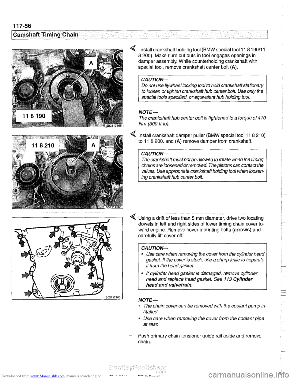
lnstall crankshaft holding tool (BMW special tool 11 8 190/11
8 200). Make sure cut outs in tool engages openings in
damper assembly. While counterholding crankshaft with
special tool, remove crankshaft center bolt (A).
CAUTION-
Do not use flywheel locking tool to hold crankshaft stationary
NOTE-
The crankshaft hub centerbolt is tightened to a torque of 410
Nm (300 ft-lb).
4 Install crankshaft damper puller (BMW special tool 11 8 210)
to 11 8 200. and (A) remove damper from crankshaft.
The crankshaft must not be allowed to rotate when the timing
chains are loosened or removed. The pistons can contact the
valves. Use appropriate crankshaft holding tool when loosen-
ing crankshaft hub center bolt.
Using a drift of less than
5 mm diameter, drive two locating
dowels in left and right sides of lower timing
cham cover to-
ward engine. Remove cover mounting bolts
(arrows) and
carefully lift cover off.
CA
UTION-
* Use care when removing the cover from the cylinder heao
gasket. If the cover is stuck, use a sharp
knife to separate
it from the headgasket.
If cylinder liead gasket Is damaged, remove cylinder
head and replace head gasket. See
113 Cylinder
head and valvetrain.
NOTE-
- The chain cover can be removed with the coolant pump in-
stalled.
Use care when removing the cover from the coolant pipe
at rear.
- Push primary chain tensioner guide rail aside and remove
chain.
Page 301 of 1002
Downloaded from www.Manualslib.com manuals search engine
Cp-- Camshaft -- Timing Chain
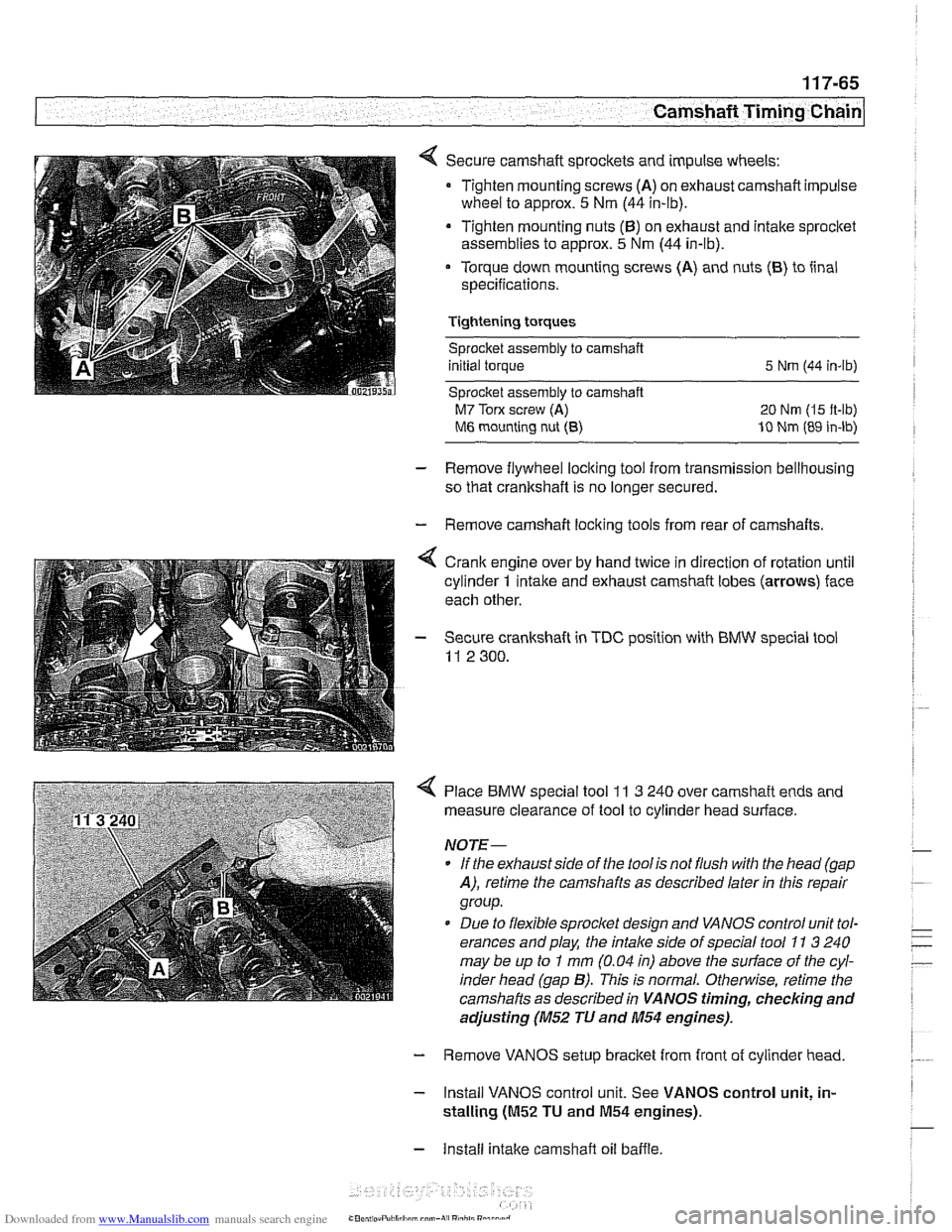
Secure camshaft sprockets and impulse wheels:
Tighten mounting screws
(A) on exhaust camshaft impulse
wheel to approx.
5 Nm (44 in-lb).
Tighten mounting nuts
(6) on exhaust and intake sprocket
assemblies to approx.
5 Nm (44 in-lb).
Torque down mounting screws (A) and nuts
(6) to iinal
specifications.
Tightening torques Sprocket assembly
to camshaft
initial torque
5 Nrn (44 in-lb)
Sprocket assembly to camshaft
M7 Torx screw (A) 20 Nm (I5 it-lb)
M6 mounting nut (8) 10 Nm (89 in-lb)
- Remove flywheel locking tool from transmission bellhousing
so that crankshaft is no longer secured.
- Remove camshaft loclting tools from rear of camshafts.
4 Crank engine over by hand twice in direction of rotation until
cylinder
1 intake and exhaust camshaft lobes (arrows) face
each other.
- Secure crankshaft in TDC position with BMW special tool
11 2 300.
4 Place BMW special tool 11 3 240 over camshaft ends and
measure clearance of tool to cylinder head surface.
NOTE-
* If the exhaust side of the tool is not flush with the head (gap
A), retime the camshafts as described laler in this repair
group.
Due to flexible sprocket design and VANOS control unit tol-
erances and play, the
intake side of special tool 71 3 240
may be up to
I mm (0.04 in) above the suriace of the cyl-
inder head (gap
B). This is normal. Otherwise, retime the
camshafts as described in
VANOS timing, checking and
adjusting (M52 TU and 11154 engines).
- Remove VANOS setup bracket from front of cylinder head
- Install VANOS control unit. See VANOS control unit, in-
stalling
(01152 TU and M54 engines).
- Install intake camshaft oil baffle
Page 319 of 1002
Downloaded from www.Manualslib.com manuals search engine
Camshaft Timing chain/
- Tighten accessible sprocket retaining bolts in the following
order:
Leit exhaust camshaft
Right exhaust
camshait
Leit intake camshaft
Right
intalte camshait
Tightening torque
Sprocket bolts to camshaft flange
15 Nm (1 1 ft-lb)
- Remove BMW special tool 11 2 300 from tool bore at bell-
housing and remove
camshaft loclting tools from cylinder
heads.
Using crankshaft center bolt, turn engine over clockwise at
least one
comolete rotation so that remainino camshaft
sprocltet
retaking bolts are accessible. -
- Tighten remaining camshait sprocket retaining bolts
Tightening torque Sprocket bolts to camshaft
flange 15 Nm (I 1 It-lb)
- Remove BMW special tool 11 3 390 from primary timing
chain tensioner bore and reinstall primary chain tensioner
- Remainder of installation is reverse or removal, noting the fol-
lowing:
Remove gasket residue from cylinder head sealing sur-
face.
Apply a thin bead of Three Bond 1209
O sealing com-
pound to joints at cylinder head cover and timing case cov-
er and at half-moon sections at rear of cylinder heads.
Replace cylinder head cover
gaskets if necessary.
Page 321 of 1002
Downloaded from www.Manualslib.com manuals search engine
11 9 Lubrication System
General ............................ 11 9-2
Special tools
......................... 11 9-2
..................... Engine lubrication 11 9-3
Troubleshooting .................... 11 9-3
................. Oil pressure. checking 11 9-4
...... Oil pressure warning system. testing 11 9-5
Crankshaft Rear Main Seal ......... .I1 9-6
Crankshaft rear main seal.
replacing (6-cylinder)
.................. 11 9-6
Crankshaft rear main seal. replacing (V-8)
. . 11 9-8
Engine Oil Pan .................... .I1 9-10
Oil pan. removing and
................. installing (6-cylinder) .I1 9-10
Lower oil pan. removing and
installing (V-8)
....................... 1 19-1 3
Upper oil pan. removing and
installing (V-8)
....................... 11 9-1 5
.......... Component Replacement 11 9-20
Oil pressure warning switch. replacing
.................. (6-cylinder and V-8) 11 9-20
Oil level warning switch. replacing
.................. (6-cylinder and V-8) 11 9-21
Oil pump. removing and
................. installing (6-cylinder) 11 9-22
Oil pump. removing and installing (V-8)
. . 11 9-24
..... Oil pressure relief valve (6-cylinder) 119-26
.......... Oil pressure
relief valve (V-8) 11 9-27
Page 322 of 1002
Downloaded from www.Manualslib.com manuals search engine
11 9-2
Lubrication System
This repair group covers lubrication system troubleshooting
as well as oil pan removal and oil pump replacement.
In 6-cylinder models, removal of the oil pan requires the re-
moval of the exhaust system and some front suspension
components. Those procedures are fully covered in:
180 Exhaust System
210 Clutch
230 Manual Transmission
0 240 Automatic Transmission
310 Front Suspension
320 Steering and Wheel Alignment
NOTE-
Oil change procedure and oil filter replacement are covered
in
020 Maintenance.
CAUTIOG
V8 engines: The oil pump fasteners (including the sprocket
retaining nut) are known to vibrate loose. This can result in oil
starvation and engine failure. Be sure to check oil bolts and
nut tightness whenever the
oilpump is accessible. If any fas-
teners are found to be loose, remove them and reinstall with
Loctite
Band torque to specifications.
Special tools
The engine needs to be properly supported while the front
suspension
subframe is lowered to access the oil pan.
A standard oil pressure gauge may be used for measuring oil
pressure.
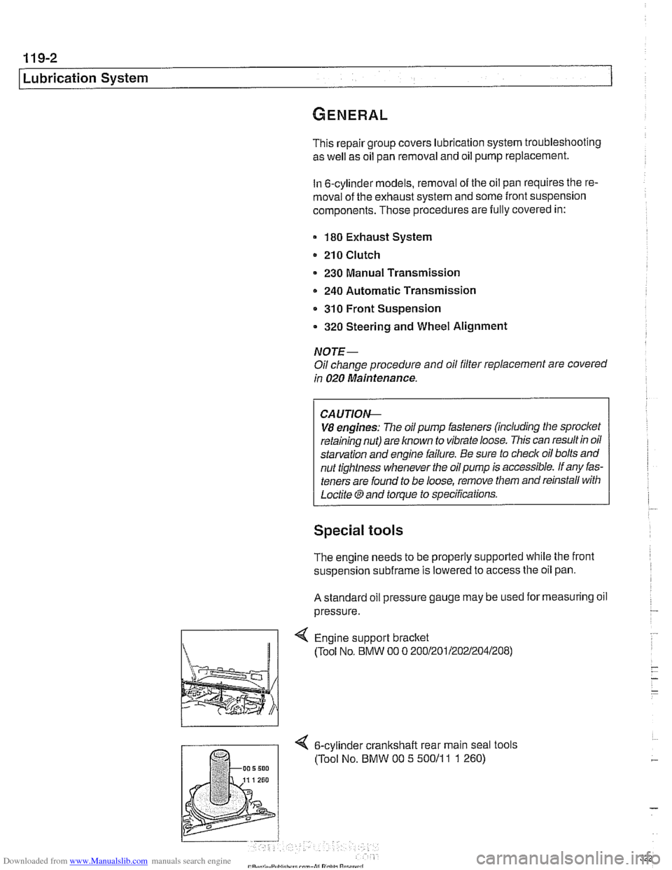
Engine support bracket
(Tool No, BMW 00 0 20012011202~2041208)
4 6-cylinder crankshalt rear main seal tools
(Tool No. BMW 00 5 50011
1 1 260)
Page 323 of 1002
Downloaded from www.Manualslib.com manuals search engine
1 19-3
Lubrication System
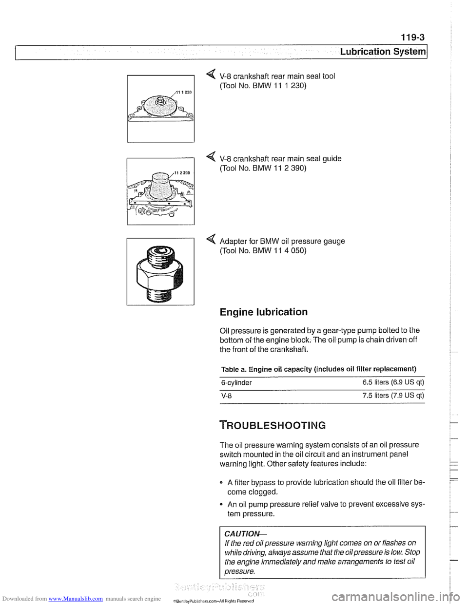
V-8 crankshaft rear main seal tool
(Tool No. BMW
11 1 230)
I i 4 V-8 crankshaft rear main seal ouide
4 Adapter for BMW oil pressure gauge
(Tool No. BMW
11 4 050)
Engine lubrication
Oil pressure is generated by a gear-type pump bolted to the
bottom oi the engine block. The oil pump is chain driven off
the front of the crankshaft.
Table a. Engine oil capacity (includes oil filter replacement)
6-cylinder 6.5
liters (6.9
US qt)
V-8 7.5 liters (7.9 US qt)
The oil pressure warning system consists of an oil pressure
switch mounted in the oil circuit and an instrument
panel
warning light. Other saiety features include:
Q A filter bypass to provide lubrication should the oil filter be-
come clogged.
An oil pump pressure relief valve to prevent excessive sys-
tem pressure.
CAUTIOI\C
If the red oil pressure warning light comes on or flashes on
while driving, always assume that the oilpressure is low. Stop
the engine immediately and make arrangements to test oil
pressure.
Page 326 of 1002
Downloaded from www.Manualslib.com manuals search engine
Lubrication System
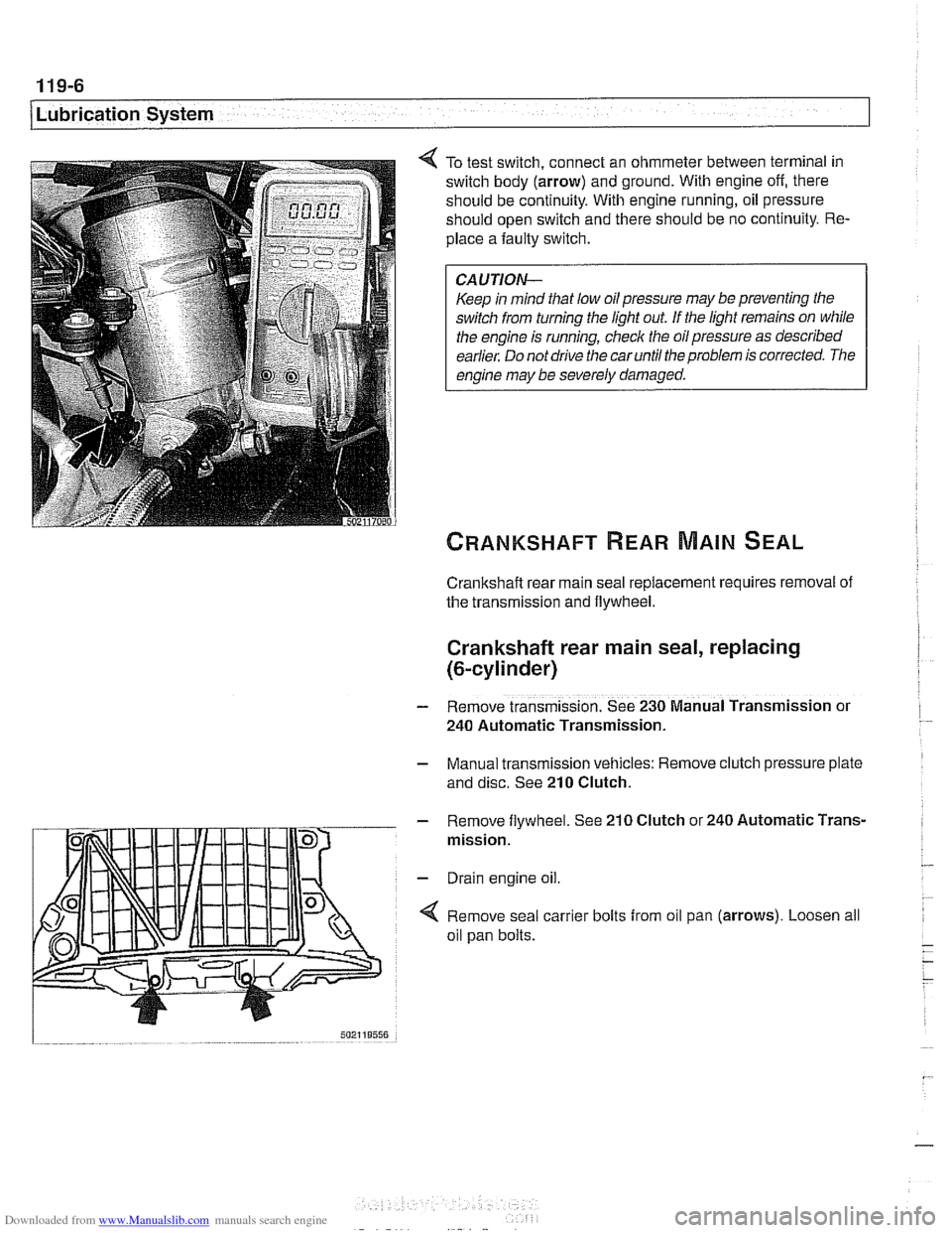
To test switch, connect an ohmmeter between terminal in
switch body (arrow) and ground. With engine off, there
should be continuity. With engine running, oil pressure
should open switch and there should be no continuity. Re-
place a faulty switch.
CAUTION-
Keep in mind that low oil pressure may be preventing the
switch from turning the light out
If the light remains on while
the engine is running, check the oil pressure as described
earlier. Do not drive the car until the problem is corrected. The
engine may be severely damaged.
Crankshaft rear main seal replacement requires removal of
the transmission and flywheel.
Crankshaft rear main seal, replacing
(&cylinder)
- Remove transmission. See 230 Manual Transmission or
240 Automatic Transmission.
- Manual transmission vehicles: Remove clutch pressure plate
and disc. See
210 Clutch.
- Remove flywheel. See 210 Clutch or 240 Automatic Trans-
mission.
- Drain engine oil.
4 Remove seal carrier bolts from oil pan (arrows). Loosen all
oil pan bolts.