rear BMW 525i 1997 E39 Owner's Guide
[x] Cancel search | Manufacturer: BMW, Model Year: 1997, Model line: 525i, Model: BMW 525i 1997 E39Pages: 1002
Page 192 of 1002
Downloaded from www.Manualslib.com manuals search engine
.
Cylinder Head and Valvetrain
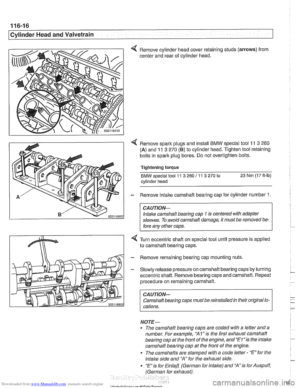
< Remove cylinder head cover retaining studs (arrows) from
center and rear of cylinder head.
< Remove spark plugs and install BMW special tool 11 3 260
(A) and 11 3 270 (6) to cylinder head. Tighten tool retaining
bolts in spark plug bores. Do not overtighten bolts.
Tightening
torque
BMW special tool 11 3 260 I1 1 3 270 to 23 Nm (17 It-lb)
cylinder head
- Remove intake camshaft bearing cap for cylinder number 1.
CA UTIOG
Intake camshaft bearing cap 1 is centered with adapter
sleeves. To avoid
can~sllaft daniage, it must be removed bs-
fore any other caps.
Turn eccentric shaft on special tool until pressure is applied
to camshaft bearing caps.
- Remove remaining bearing cap mounting nuts
- Slowly release pressure on camshaft bearing caps by turning
eccentric shaft. Remove bearing caps and camshaft. Repeat
procedure on remaining camshaft.
CAUTION-
Camshaft bearing caps must be reinstalled in their original lo-
cations.
NOTE-
The camshaft bearing caps are coded with a letter anda
number. For example,
'XI" is the first exhaust camshaft
bearing cap at the front of the engine, and
"El "is the intalce
camshaft bearing cap at the front of the engine.
0 The camshafts are stamped with a code letter - "E" for the
intake side and 'MA" for the exhaust side.
0 "E is for Einlap, (German for intake) and 'XA"is for Auspuff,
(German for exhaust).
Page 200 of 1002

Downloaded from www.Manualslib.com manuals search engine
..--.
I Cylinder Head and Valvetrain - I
4 Lift primary chain and hold under tension, rotate engine
against direction of rotation (counterclockwise) approximate-
ly 30".
To prevent damaging valves while
worlcing on camshafts, no
aistons should be in the TDC position.
- Remove BMW special tool set 1 I 3 240 from rear of cylinder
head.
Remove retaining nuts (arrows) and bearing cap
1 of intake
camshaft.
Intake camshaft bearing cap
1 is centered with adapter
sleeves. To avoid camshaft damage, it must be removed be-
fore anv other caos.
4 Fit BMW special tools 11 3 260 (A) and 11 3 270 (B) to cylin-
der head and screw long bolts (aiiows) into spark plug
threads. Tensioners will align with the bearing caps on the in-
take camshaft.
CA UTION--
Do not over torque bolts into spark plug holes. 1
4 Turn eccentric shaft of special tool to pretension intake carn-
shaft bearing caps. Remove nuts on remaining bearing caps.
- Slowly release tension on eccentric shaft and remove BMW
special tools. Remove bearing caps and set aside in order.
Remove camshaft and store safely.
CA U TIOW-
Camshaft bearing caps must be installed in their original lo-
cations.
Page 222 of 1002
Downloaded from www.Manualslib.com manuals search engine
11 6-46
/cylinder Head and Valvetrain
I I Camshafts, installing, right cylinder head (M62 engine)
I
1
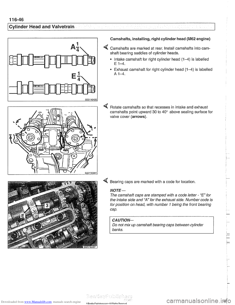
A: / Camshafts are marked at rear. Install camshafts into cam-
shaft bearing saddles of cylinder heads.
Intake camshaft for right cylinder head
(14) is labelled
E 1-4.
Exhaust camshaft for right cylinder head (1-4) is labelled
A 1-4.
4 Rotate camshafts so that recesses in Intake and exhaust
camshafts
polnt upward 30 to 40' above seal~ng surface for
valve cover (arrows).
4 Bearing caps are marked with a code for location.
NOTE-
The camshaft caps are stamped with a code letter - "E" for
the intake side and
'N" for the exhaust side. Number code is
forposition on head, with number
7 being the front bearing
cap.
CAUTION--
Do not mix up camshafi bearing caps between cylinder
banks.
Page 224 of 1002
Downloaded from www.Manualslib.com manuals search engine
1 16-48
/Cylinder Head and Valvetrain
Cylinders
1-4
11 2 445 11 2441
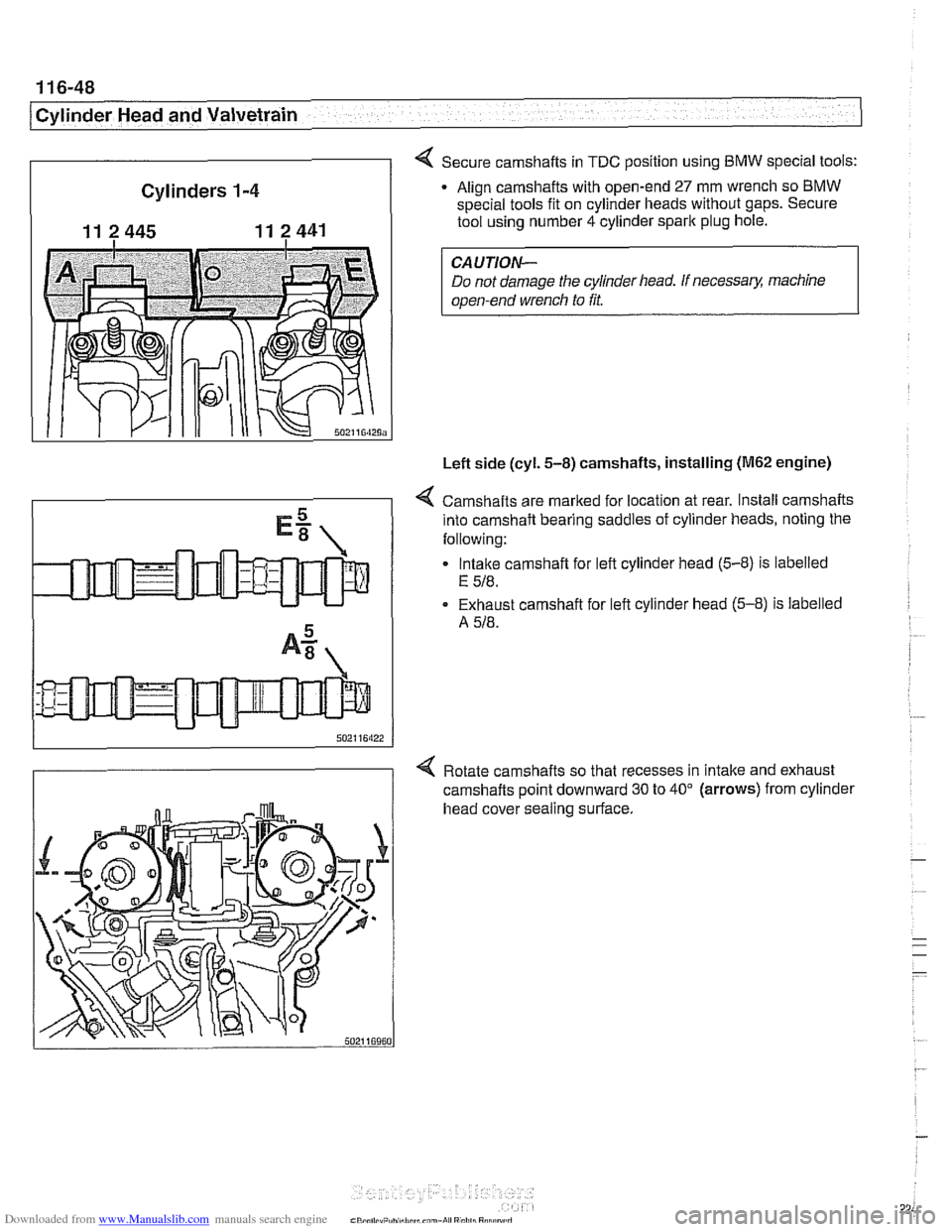
4 Secure camshafts in TDC position using BMW special tools:
Align camshafts with open-end
27 mm wrench so BMW
special tools fit on cylinder heads without gaps. Secure
tool using number 4 cylinder spark plug hole.
Do not damage the cylinder head. If
necessa& machine
open-end wrench to fit.
Left side (cyl.
5-8) camshafts, installing (M62 engine)
4 Camshafts are marked for location at rear. Install camshafts
into camshaft bearing saddles of cylinder heads, noting the
following:
Intake camshaft for left cylinder head
(5-8) is labelled
E 518.
Exhaust camshaft for left cylinder head (5-8) is labelled
A
518.
4 Rotate camshafts so that recesses in intake and exhaust
camshafts point downward 30 to 40" (arrows) from cylinder
head cover sealing surface.
Page 231 of 1002
Downloaded from www.Manualslib.com manuals search engine
11 6-55
Cvlinder Head and valvetrain1
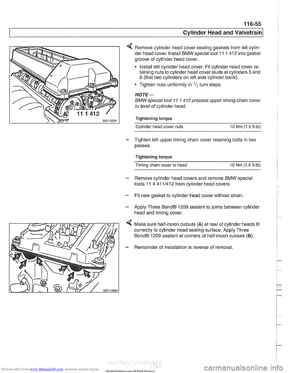
4 Remove cylinder head cover sealing gasltets from left cylin-
der head cover. Install BMW special tool 11 1 412 into gasket
groove of cylinder head cover.
Install left cylinder head cover. Fit cylinder head cover re-
taining nuts to cylinder head cover studs at cylinders
5 and
6 (first two cylinders on left side cylinder bank).
* Tighten nuts uniformly in 'I? turn steps.
NOTE-
BMW special tool 11 1 4 12presses upper timing chain cover
to level of cylinder head.
Tightening torque Cylinder head cover
nuts 10 Nm (7.5 it-lb)
- Tighten left upper timing chain cover retaining bolts in two
passes.
Tightening torque
Timing chain cover to head
10 Nm (7.5 ft-lb)
- Remove cylinder head covers and remove BMW special
tools 11 4 41 11412 from cylinder head covers.
- Fit new gasket to cylinder head cover without strain.
- Apply Three Bond@ 1209 sealant to joints between cylinder
head and timing cover.
4 Malte sure half-moon cutouts (A) at rear of cylinder heads fit
correctly to cylinder head sealing surface. Apply Three
Bond@ 1209 sealant at corners of half-moon cutouts (B).
- Remainder of installation is reverse of removal.
Page 253 of 1002
Downloaded from www.Manualslib.com manuals search engine
Camshaft Timing Chain
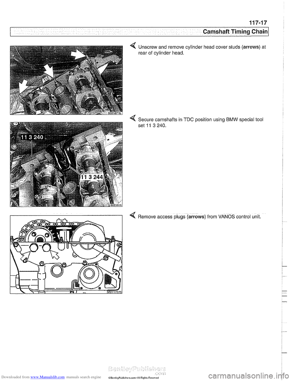
4 Unscrew and remove cylinder head cover studs (arrows) at
rear of cylinder head.
% Secure camshafts in TDC position using BMW special tool
set
11 3 240.
4 Remove access plugs (arrows) from VANOS control unit.
Page 261 of 1002
Downloaded from www.Manualslib.com manuals search engine
-
Camshaft Timing Chain -. -
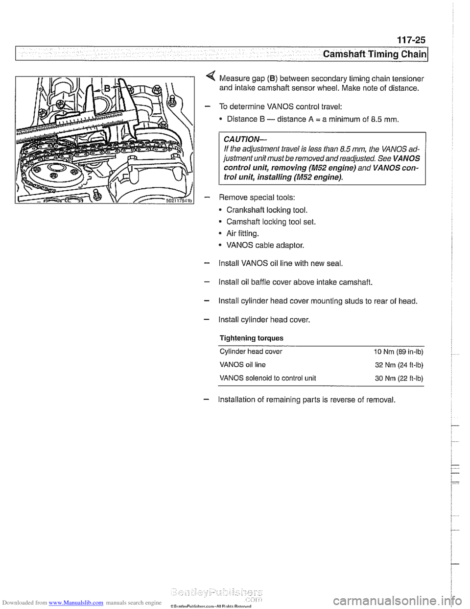
Measure gap (B) between secondary timing chain tensioner
and intake camshaft sensor wheel. Make note of distance.
To determine VANOS control travel:
Distance
I3 - distance A = a minimum of 8.5 mm
CAUTION-
If the adjustment travel is less than 8.5 mm the VANOS ad-
justment unit must be removed and readjusted. See
VANOS
control unit, removing (M52 engine)
and VANOS con-
trol unit, installing
(M52 engine).
Remove special tools:
Cranltshaft locking tool.
Camshaft
loclting tool set.
Air fitting.
* VANOS cable adaptor.
- Install VANOS oil line with new seal
- Install oil baffle cover above intake camshaft.
- Install cylinder head cover mounting studs to rear of head.
- Install cylinder head cover,
Tightening
torques
Cylinder head cover 10 Nrn (89 in-lb)
VANOS oil line
32 Nm (24 R-lb)
VANOS solenoid to control unit 30 Nrn (22 ft-lb)
- Installation of remaining parts is reverse of removal.
Page 265 of 1002
Downloaded from www.Manualslib.com manuals search engine
Camshaft Timing chain1
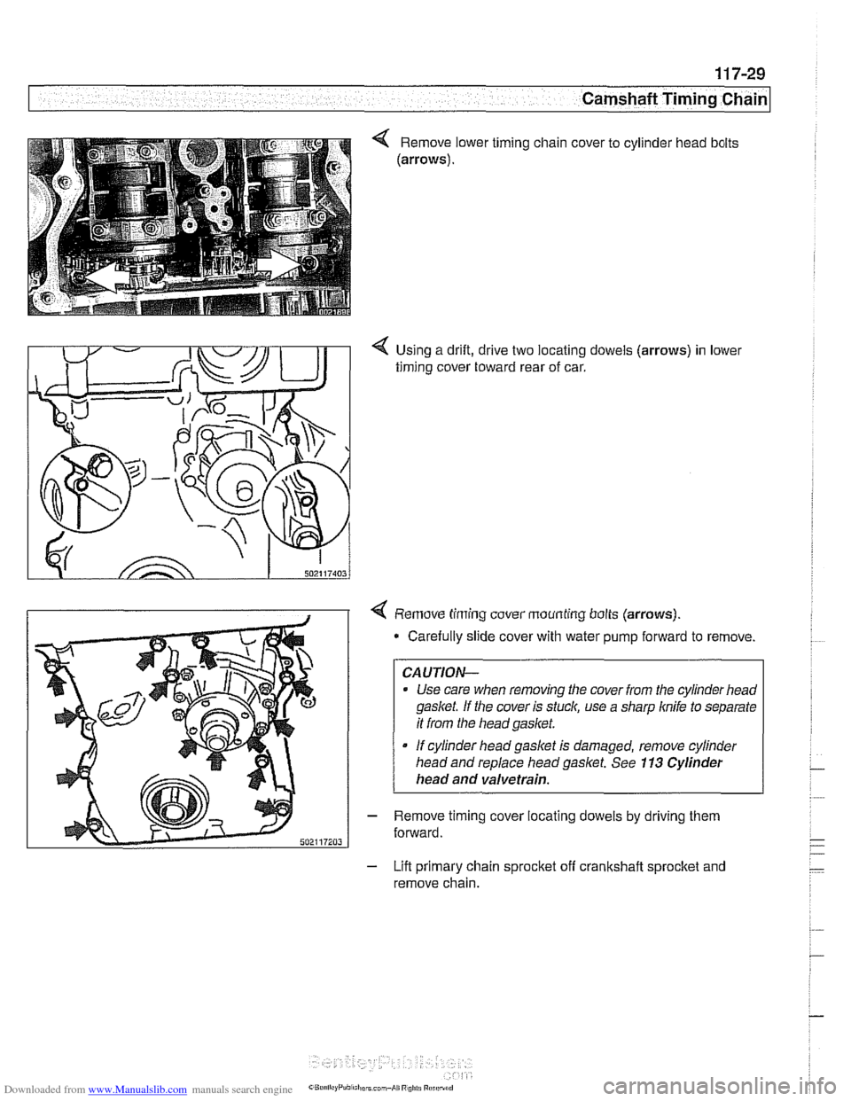
Using a drift, drive two locating dowels (arrows) in lower
timing cover toward rear of car.
4 Remove timing cover mounting bolts (arrows).
* Carefully slide cover with water pump forward to remove
CAUTION-
Use care when removing the cover from the cylinder head
gasket If the cover is stuck, use a sharp knife to separate
it from the head gasket.
If cylinder head gasket is damaged, remove cylinder
head and replace head
gaslet. See 113 Cylinder
head and valvetrain.
- Remove timing cover locating dowels by driving them
forward.
- Lift primary chain sprocket off crankshaft sprocket and
remove chain.
Page 275 of 1002
Downloaded from www.Manualslib.com manuals search engine
11 7-39
Camshaft Timing Chain
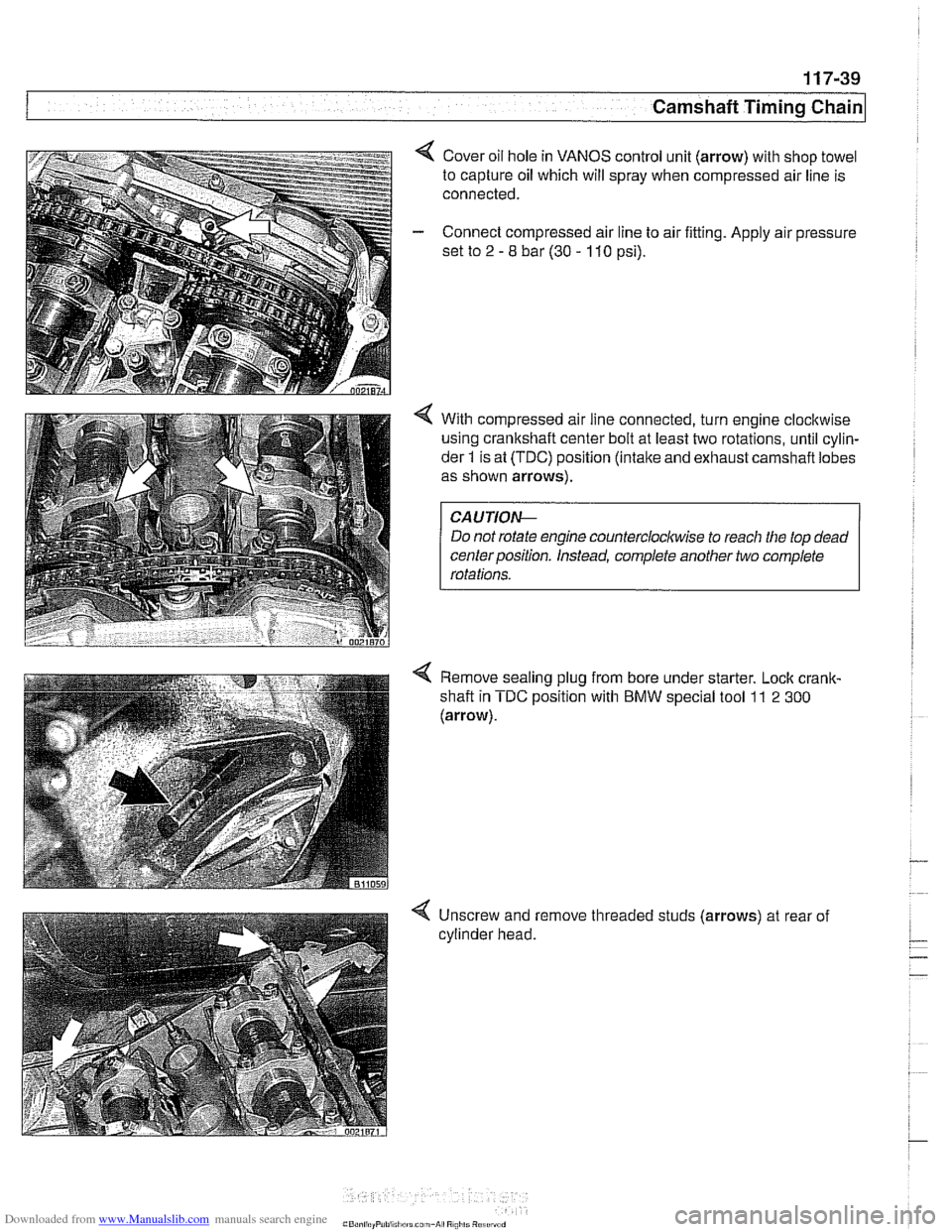
4 Cover oil hole in VANOS control unit (arrow) with shop towel
to capture oil which will spray when compressed air line is
connected.
- Connect compressed air line to air fitting. Apply air pressure
set to
2 - 8 bar (30 - 110 psi).
4 With compressed air line connected, turn engine clocltwise
using crankshaft center bolt at least two rotations, until cylin-
der
1 is at (TDC) position (intake and exhaust carnshafl lobes
as shown arrows).
Do not rotate engine
countercloclwise to reach the top dead
centerposition. Instead, complete another two complete
Remove sealing plug from bore under starter. Lock
crank-
shafl in TDC position with BMW special tool 11 2 300
(arrow).
-
4 Unscrew and remove threaded studs (arrows) at rear of
cylinder head.
Page 279 of 1002
Downloaded from www.Manualslib.com manuals search engine
Camshaft Timing Chain
- Connect electrical harness connectors to camshaft position
sensors and VANOS solenoid valves.
- Remove BMW special locking tools from rear of cylinder
head.
- Remove cranltshaft locking tool and replace sealing plug.
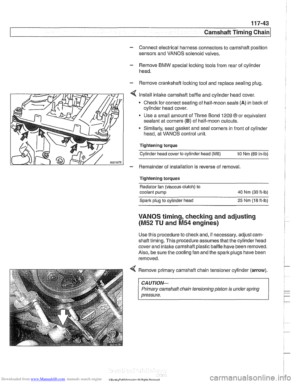
Install intake camshaft baffle and cylinder head cover.
Checlc for correct seating of half-moon seals (A) in back of
cylinder head cover.
Use a small amount of Three Bond 1209
O or equivalent
sealant at corners
(B) of half-moon cutouts.
Similarly, seat gasket and
seal corners in front of cylinder
head, at VANOS control unit.
Tightening torque
Cylinder head cover to cylinder head
(M6) 10 Nm (89 in-lb)
- Remainder of installation is reverse of removal.
Tightening torques
Radiator fan (viscous clutch) to
coolant pump 40
Nm (30 ft-lb)
Spark plug to cylinder head
25 Nrn (18 ft-lb)
VANOS timing, checking and adjusting
(M52 TU and M54 engines)
Use this procedure to check and, if necessary, adjust cam-
shaft timing. This procedure assumes that the cylinder head
cover and intake
camshaft plastic baffle have been removed.
Also, be sure the cooling fan and the spark plugs have been
removed.
Remove primary camshaft chain tensioner cylinder
(arrow).
~~ ~ ~~ ~--~
CA UTlOAC
Primary camshaft chain tensioning piston is under spring
pressure.