rear BMW 525i 1997 E39 Repair Manual
[x] Cancel search | Manufacturer: BMW, Model Year: 1997, Model line: 525i, Model: BMW 525i 1997 E39Pages: 1002
Page 327 of 1002
Downloaded from www.Manualslib.com manuals search engine
Lubrication stern/
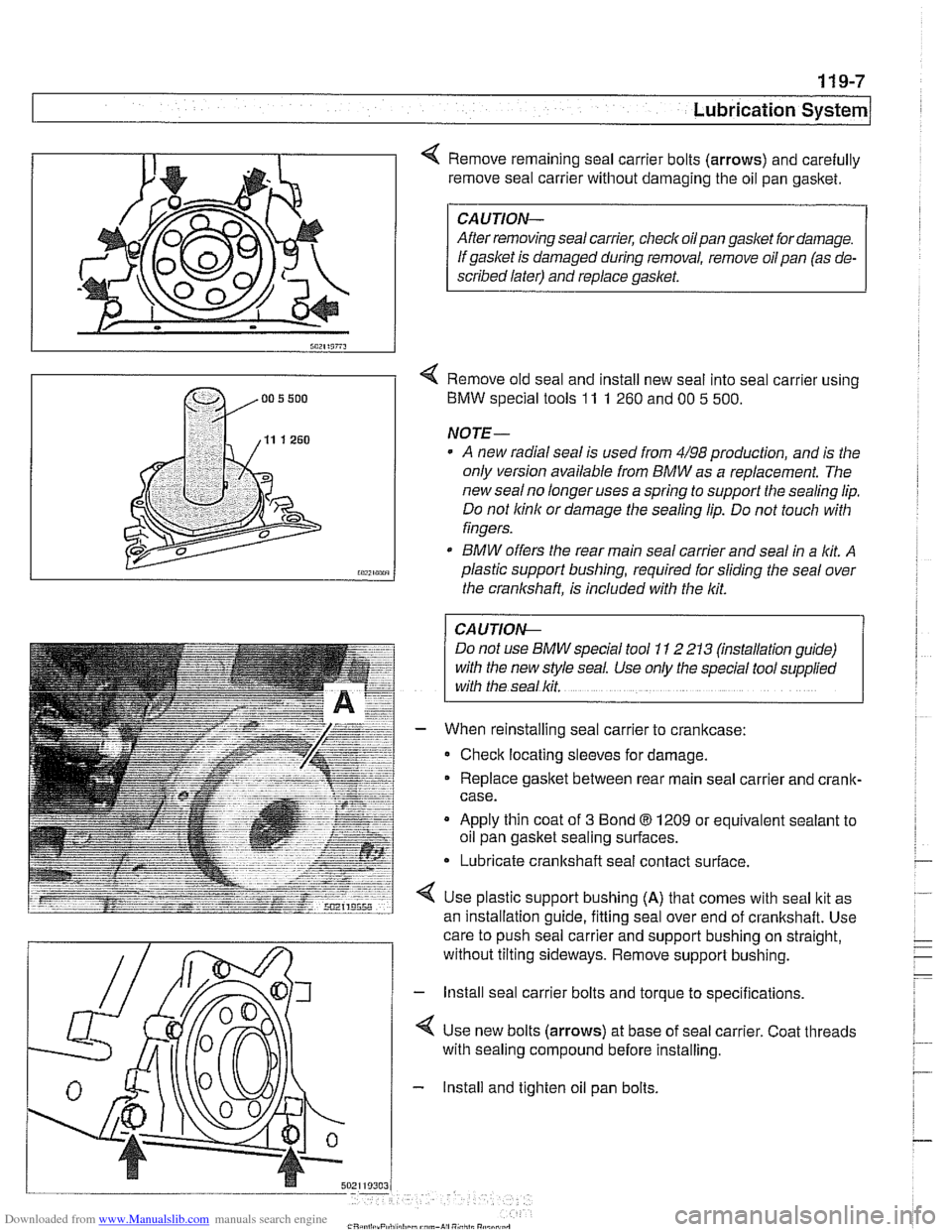
Remove remaining seal carrier bolts (arrows) and carefully
remove seal carrier without damaging the oil pan
gasltet.
CAUTION-
After removing seal carrier, checlc oilpan gasket for damage.
If gasket is damaged during removal, remove oil pan (as de-
scribed later) and replace
gasket.
< Remove old seal and install new seal into seal carrier using
BMW special tools
11 1 260 and 00 5 500.
NOTE-
A new radial seal is used from 4/98 production, and is the
only version available from
BMW as a replacement. The
new
sealno longer uses a spring to support the sealing lip.
Do not
lcinlc or damage the sealing lip. Do not touch with
fingers.
* BMW offers the rear main seal carrier and seal in a lit A
plastic support bushing, required for sliding the seal over
the crankshaft, is included with the
lcit.
I CAUTION- 1
Do not use BMW special tool 1 I 2 213 (mstallation guide)
with the new style seal. Use only the special tool
supphed
with the seal lcit.
When reinstalling seal carrier to crankcase:
Check locating sleeves for damage.
Replace
gasltet between rear main seal carrier and crank-
case.
Apply thin coat of
3 Bond 8 1209 or equivalent sealant to
oil pan gasket sealing surfaces.
* Lubricate crankshaft seal contact surface.
Use plastic support bushing
(A) that comes with seal ltit as
an installation
quide, fittina seal over end of crankshaft. Use - -
care to push seal carrier and support bushing on straight,
without tilting sideways. Remove support bushing.
- lnstall seal carrier bolts and torque to specifications.
4 Use new bolts (arrows) at base of seal carrier. Coat threads
with sealing compound before installing.
- Install and tighten oil pan bolts.
Page 328 of 1002
Downloaded from www.Manualslib.com manuals search engine
I Lubrication System -
- Remainder of assembly is reverse of disassembly.
Install flywheel, clutch or torque converter and
transmission.
Fill engine with oil.
- Run engine and check for leaks.
Tightening torques
Oil
drain plug fo oil pan (MI21 25 Nm (18 ft-lb)
Oil pan to engine
block
M6 (8.8 grade) 10 Nm (89 in-ib)
M6 (1 0.9 grade) 12 Nm (9 ft-lb)
M8 (8.8 grade) 22 Nm (1 6 it-lb)
Rear main seal carrier to crankcase
M6 10 Nm (89 in-lb)
ME 22 Nm (16 ft-lb)
Crankshaft rear main seal, replacing (V-8)
- Remove transmission. See 230 Manual Transmission or
240 Automatic Transmission.
- Manual transmission vehicles: Remove clutch pressure plate
and disc. See
210 Clutch.
- Remove flywheel. See 210 Clutch.
- Drain engine oil.
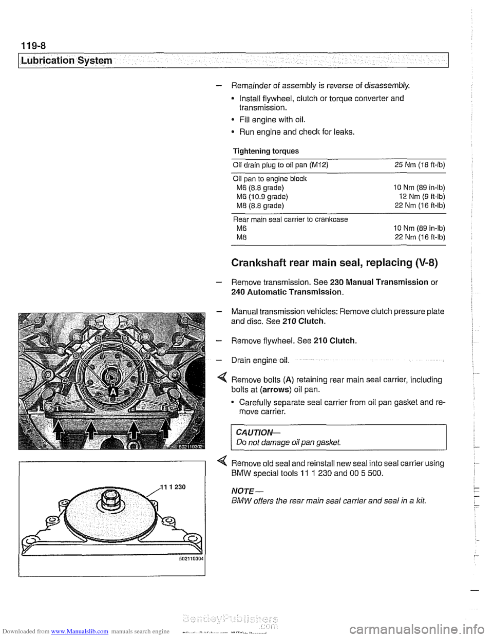
4 Remove bolts (A) retaining rear main seal carrier, including
bolts at (arrows) oil pan.
Carefully separate seal carrier from oil pan gasket and re-
move carrier.
CAUTION-
Do not damage oil pan gasket.
< Remove old seal and reinstall new seal into seal carrier using
) BMW special tools 11 1 230 and 00 5 500.
Page 329 of 1002
Downloaded from www.Manualslib.com manuals search engine
- When reinstalling seal carrier to crankcase:
Check locating sleeves for damage.
Replace gasitet between rear main seal carrier and
cranlt-
case.
Apply thin coat of
3 Bond 8 1209 or equivalent sealant to
oil pan
gasltet sealing surfaces.
* Lubricate crankshaft and seal contact surfaces.
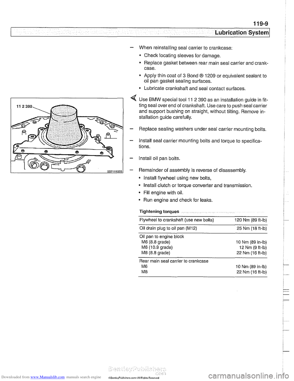
4 Use BMW special tool 11 2 390 as an installation guide in fit-
ting seal over end of cranltshaft. Use care to push seal carrier
and support bushing on straight, without tilting. Remove in-
stallation guide carefully.
- Replace sealing washers under seal carrier mounting bolts.
- Install seal carrier mounting bolts and torque to specilica-
tions.
- lnstall oil pan bolts.
- Remainder of assembly is reverse of disassembly.
Install flywheel using new bolts,
Install clutch or torque converter and transmission.
* Fill engine with oil.
Run engine and
checlt for leaks.
Tightening torques Flywheel to crankshaft (use new bolts)
120 Nm (89 ft-lb)
011 dra~n plug to 011 pan (M12) 25 Nm (18 ft-lb)
Oil pan to
eng~ne block
M6 (8.8 grade) 10 Nm (89 in-lb)
M6 (1 0 9 grade) 12 Nm (9 ft-lb)
M8 (8.8 grade) 22 Nm (16 ft-lb)
Rear main seal carrier to crankcase
M6 10 Nrn (89 in-lb)
ME 22 Nm (16 ft-lb)
Page 340 of 1002
Downloaded from www.Manualslib.com manuals search engine
Lubr~cat~on System r- -
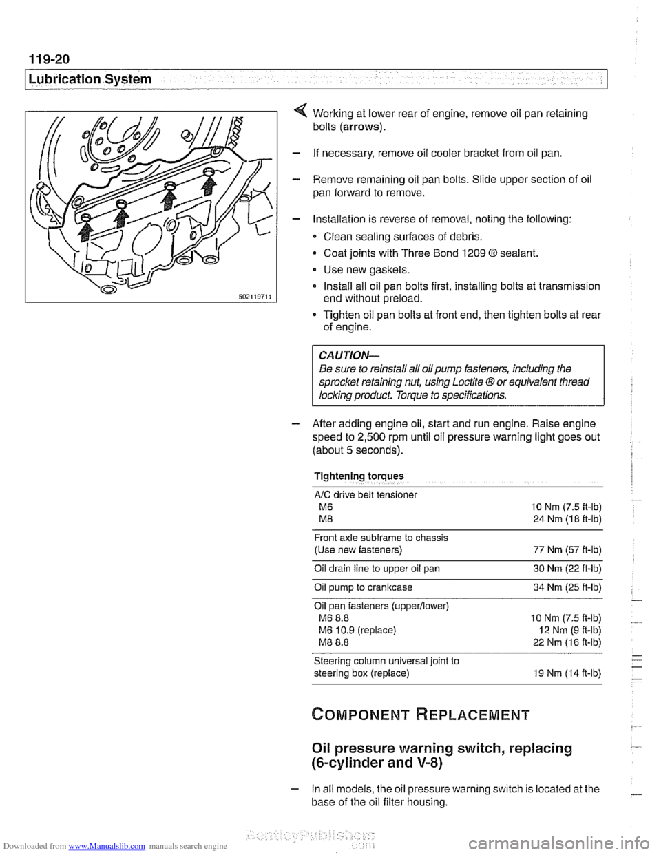
Working at lower rear of engine, remove oil pan retaining
bolts
(arrows).
- If necessary, remove oil cooler bracket from oil pan.
- Remove remaining oil pan bolts. Slide upper section of oil
pan forward to remove.
- Installation is reverse of removal, noting the following:
Clean sealing surfaces of debris.
- Coat joints with Three Bond 1209 O sealant.
Use new gaskets.
Install all oil pan bolts first, installing bolts at transmission
end without preload.
Tighten oil pan bolts at front end, then tighten bolts at rear
of engine.
Be sure to reinstall all oil
pump fasteners, including the
sprocl
speed to
2,500 rpm until oil pressure warning light goes out
(about
5 seconds).
Tightening torques
AIC drive belt tensloner
M6 10 Nm (7.5 it-lb)
M8 24 Nm (18 ft-lb)
Front axle
subframe to chassis
(Use new fasteners) 77 Nm (57 ft-lb)
Oil drain
line to upper oil pan 30 Nm (22 ft-lb)
Oil pump to crankcase 34 Nm (25 ft-lb)
Oil pan fasteners
(upperllower)
M6 8.8 10 Nm (7.5 ft-lb)
M6 10.9 (replace)
I2 Nm (9 ft-lb)
M8 8.8 22 Nm (16 ft-lb)
Steering column universal joint to
steering box (replace) 19 Nm (14 ft-lb)
Oil pressure warning switch, replacing
(&cylinder and V-8)
- In all models, the oil pressure warning switch is located at the
base of the oil filter housing.
Page 358 of 1002
Downloaded from www.Manualslib.com manuals search engine
.-
ignition System
Disabling ignition system
The ignition system operates in a lethal voltage range and
should be disabled any time engine service or repair work is
being done that requires the ignition to be switched on.
The engine management system can be disabled by remov-
ing the DME main relay. The relay is located in the electronics
box (E-box) in the left rear of the engine
compartment, be.
neath the interior microfilter housing.
CAUTION- Relay locations may
vary. Use care when identifying relays.
See
610 Electrical Component Locations.
Checking for spark
CAUTION-
If
a spark test is done incorrecth damage to the Engine Con-
trol Module
(ECM) or the ignition coils may result.
NOTE-
Spark plug replacement is covered in 020 Maintenance.
Check~ng for spark is d~fflcult on englnes wlth d~str~butorless
ignition systems.
Try removing the spark plugs and inspecting for differences between them.
A poor-firing plug may be wet with fuel and/or ~. - ~
black and sooty, but not always. If a coil is not operating, the
engine management system will electrically disable the fuel
injector to that cylinder. The key is to look for differences be-
tween cylinders.
Ignition coil assembly, testing and
replacing
C4 UTION-
Use a digital multimeter for the following tests. I
- Remove plastic engine cover from top of valve cover by pry-
ing off bolt covers and removing cover mounting bolts.
- Raise car slowly while constantly checking position of jack
and car.
- Disconnect harness connector from coil. Connect multimeter
between terminal 15
(+) in connector and ground.
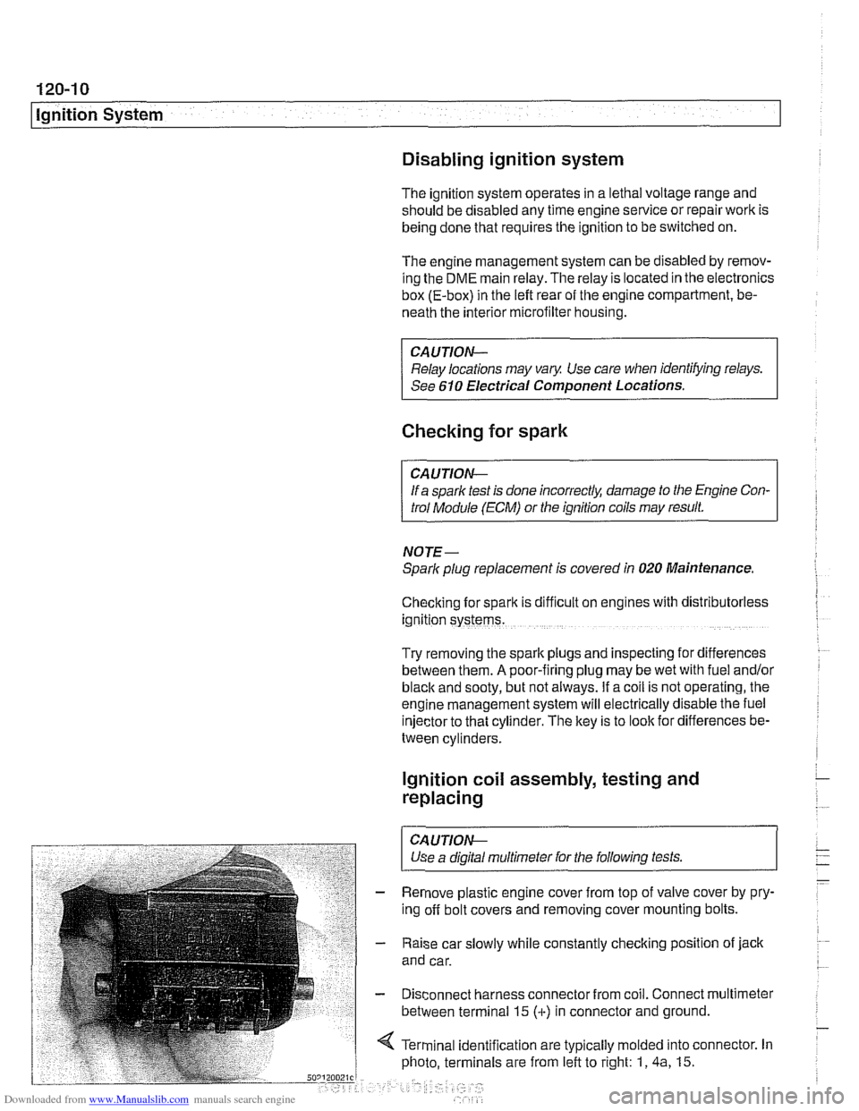
4 Terminal identification are typically molded into connector. In
photo, terminals are from left to right: 1,
4a, 15.
Page 360 of 1002
Downloaded from www.Manualslib.com manuals search engine
120-1 2
ignition System
Crankshaftspeedsensor
Crankshaft speed sensor, replacing (M52, M52 TU and
M54 engines)
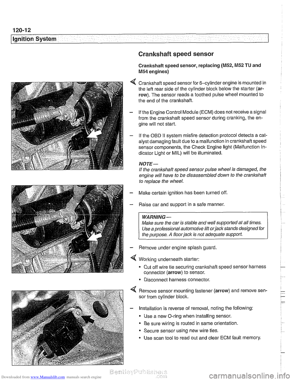
4 Crankshaft speed sensor for 6-cylinder engine is mounted in
the left rear side of the cylinder block below the starter (ar-
row). The sensor reads a toothed pulse wheel mounted to
the end of the crankshaft.
- if the Engine Control Module (ECM) does not receive a signal
from the crankshaft speed sensor during cranking, the en-
gine will not start.
- If the OBD II svstem misfire detection ~rotocol detects a cat- - - ~~
alysr oarnagin; faLlt oJe to a ma I-nclion in crandshafi speeo
sensor components. Ine Check Engine
lignr (Malfuncrion In-
dicator Light or MIL) will be illuminated.
NOTE-
If the crankshaft speed sensor pulse wheel is damaged, the
engine will have to be disassembled down to the crankshaft
to
reolace the wheel.
- Make certain ignition has been turned off.
- Raise car and support in a safe manner.
WARNING -
Make sure the car is stable and well supported at all times.
Use a professional automotive lift orjacltstands designed for
the ouroose.
A floor iaclc is not adequate support.
- Remove under engine splash guard
4 Working underneath starter:
Cut off wire tie securing crankshaft speed sensor harness
connector (arrow) to sensor.
* Disconnect harness connector.
4 Remove sensor mounting fastener (arrow) and remove sen-
sor from cylinder block.
- Installation is reverse of removal, noting the following:
Use a new O-ring when installing sensor.
Be sure wiring is routed in same orientation.
Secure sensor using new wire ties.
Use scan tool to read out and clear ECM fault memory.
Page 377 of 1002
Downloaded from www.Manualslib.com manuals search engine
121-11
Battery, Starter, ~lternatorl
Alternator 1997 - 98 5281 1997 540i
/-- -----,
I'
-----------
F15 / 7.5A/ :
&.. .... , 30 1 Xi0015
Battery
Hol in run 61 E (D+) Alternator
and stsrt
lBL
(Generator)
1 .--------,charge , . I , indicator I xGoli i
I <"9,7,a,T
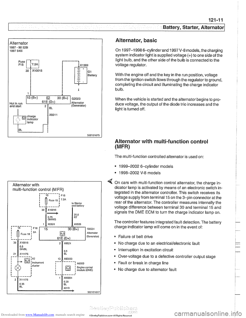
Alternator, basic
On 1997-1 998 6-cylinderand 1997 V-8 models, the charging
system indicator light is supplied voltage
(+) to one side of the
light bulb, and the other side of the bulb is connected to the
voltage regulator.
With the engine off and the key in the run position, voltage
from the ignition switch flows through the regulator to ground,
completing the circuit and illuminating the charge indicator
bulb.
When the vehicle is started and the alternator begins to pro-
duce voltage, the output of the diode trio increases and the
light is turned off.
Alternator with multi-function control
(MFR)
Alternator with multi-function control
(MFR)
The multi-function controlled alternator is used on:
* 1999-2002 6-cylinder models
* 1998-2002 V-8 models
4 On cars with multi-function control alternator, the charge in-
dicator lamp is activated by means of an electronic switch in-
tegrated in the alternator controller. This switch receives its
voltage supply from terminal
15 on the 3-pin connector at the
rear of the alternator. The controller measures internally the
voltage difference between terminal 30 and terminal
15 and
signals the DME ECM to turn the charge indicator lamp on.
The controller features integrated fault detection. The battery
charge indicator lamp will come on in the event of:
* Failure of belt drive
No charge due to an
electrical/electronic fault
Interruption in excitation circuit
Over-voltage due to a defective controller output stage Fault or break in charge line
No charge due to alternator fault
Page 380 of 1002
Downloaded from www.Manualslib.com manuals search engine
- -
/Battery, Starter, Alternator -- - -. - --I
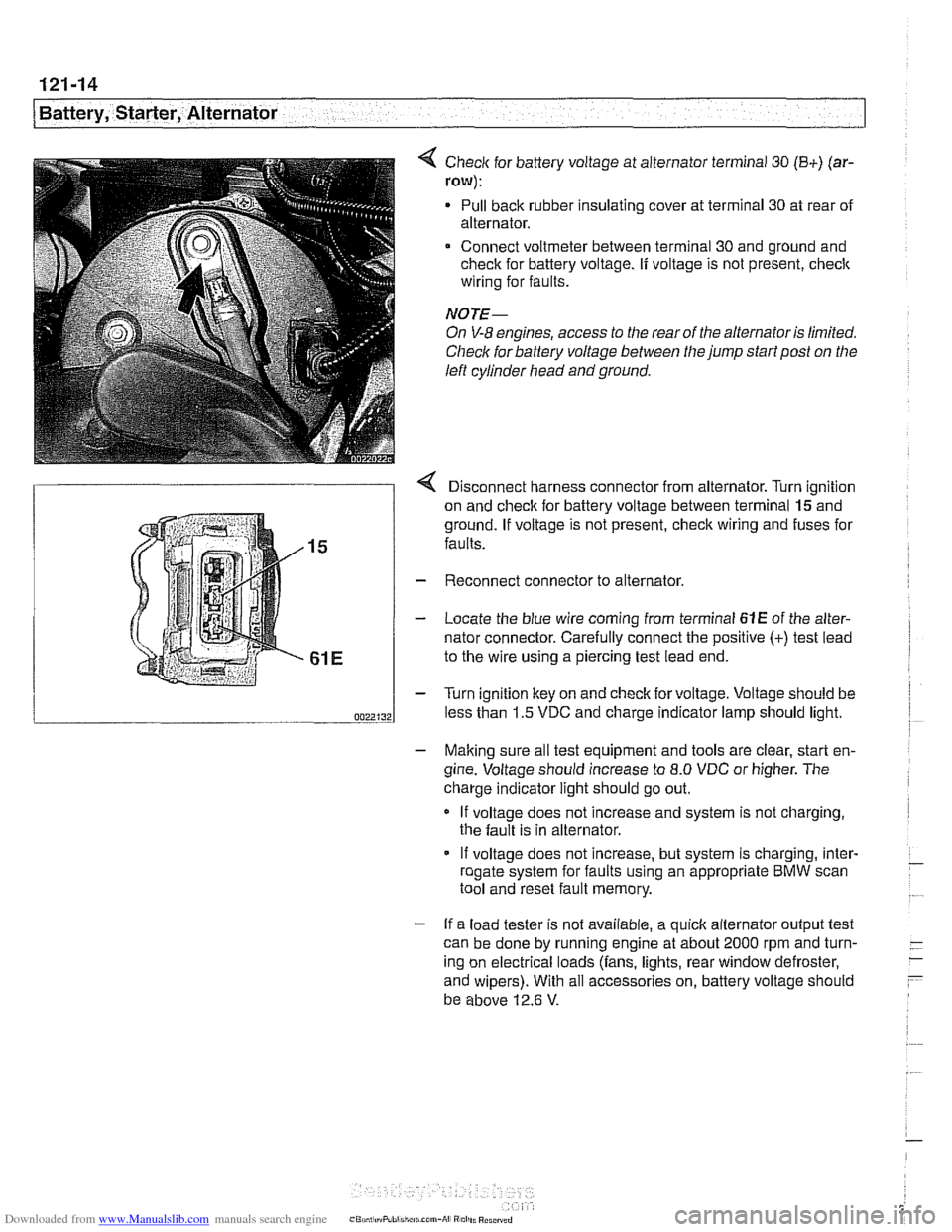
< Check for battery voltage at alternator terminal 30 (B+) (ar-
row):
Pull back rubber insulating cover at terminal 30 at rear of
alternator.
Connect voltmeter between terminal 30 and ground and
check for battery voltage.
If voltage is not present, check
wiring for faults.
NOTE-
On V-8 engines, access to the rear of the alternator is limited.
Check for battery voltage between the jump start post on the
left cylinder head and ground.
r Disconnect harness connector from alternator. Turn ianition
on and check for battery voltage between terminal
lgand
ground. If voltage is not present, check wiring and fuses for
faults.
Reconnect connector to alternator.
Locate the blue wire coming from terminal
61E of the alter-
nator connector. Carefully connect the positive
(+) test lead
to the wire using a piercing test lead end.
Turn ignition key on and check for voltage. Voltage should be
less than 1.5 VDC and charge indicator lamp should light.
- Making sure all test equipment and tools are clear, start en-
gine. Voltage should increase to
8.0 VDC or higher. The
charge indicator light should go out.
If voltage does not increase and system is not charging,
the fault is in alternator.
- If voltage does not increase, but system is charging, inter- - roaate svstem for faults usina an appropriate BMW scan - .. . tool and'reset fault memory.
- If a load tester is not available, a quick alternator output test
can be done by running engine at about 2000 rpm and turn-
- -
ing on electrical loads (fans, lights, rear window defroster, -
- and wipers). With all accessories on, battery voltage should
be above 12.6
V.
Page 381 of 1002
Downloaded from www.Manualslib.com manuals search engine
Battery, Starter, ~lternatorl
Alternator, removing and installing
(6-cylinder engine)
A replacement alternator should have the same rating as the
original. Alternator manufacturer and ampere rating are nor-
mally marked on the alternator housing.
- Disconnect negative (-) battery cable.
CAUTION-
Prior to disconnecting the batteg read the battery discon-
nection cautions given
in 001 General Warnings and Cau-
I tions.
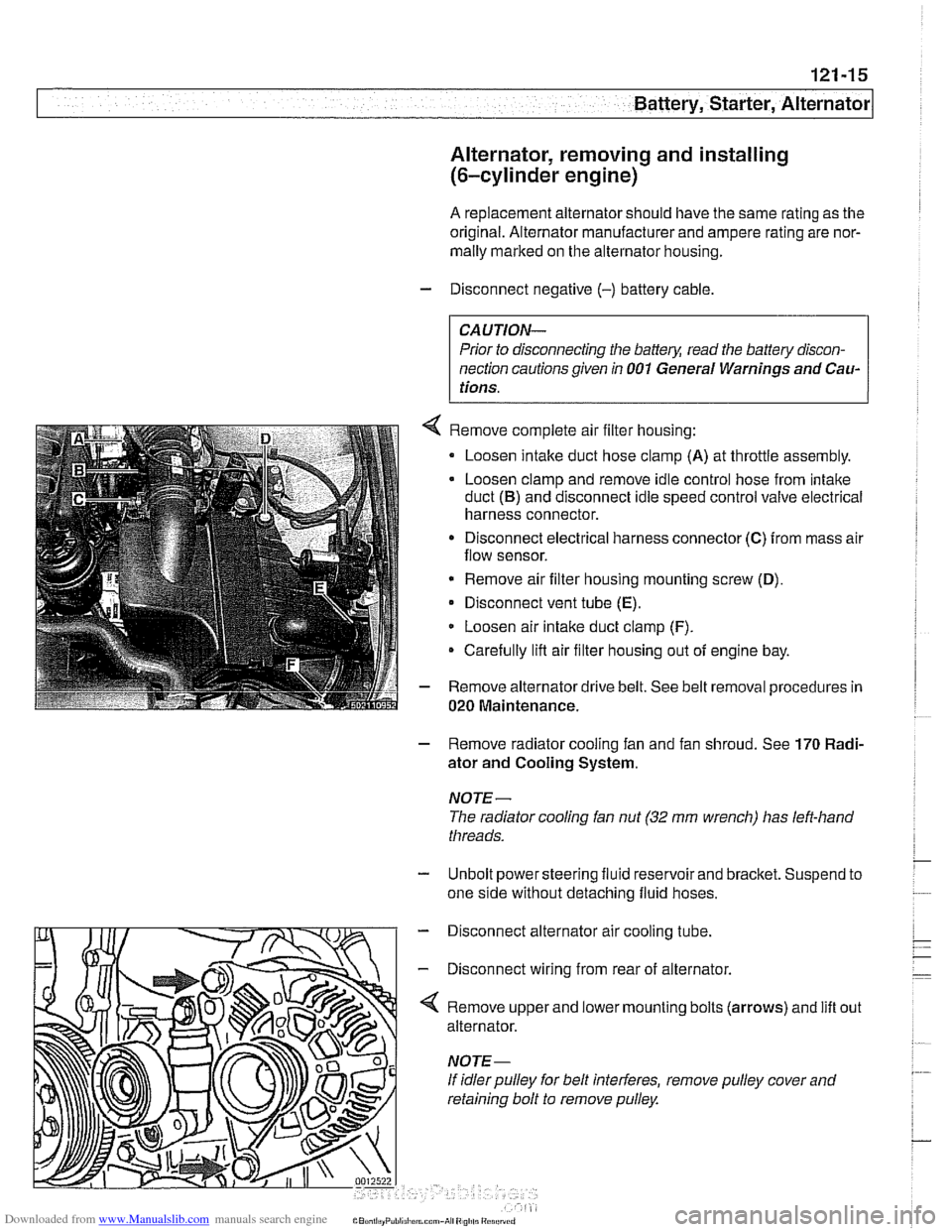
Remove complete air filter housing:
Loosen intake duct hose clamp
(A) at throttle assembly.
Loosen clamp and remove idle control hose from intake
duct
(B) and disconnect idle speed control valve electrical
harness connector.
Disconnect electrical harness connector
(C) from mass air
flow sensor.
* Remove air filter housing mounting screw (D),
Disconnect vent tube (E).
Loosen air intake duct clamp (F).
Carefully lifl air filter housing out of engine bay.
Remove alternator drive belt. See belt removal procedures in
020 Maintenance.
- Remove radiator cooling fan and fan shroud. See 170 Radi-
ator and Cooling System.
NOTE-
The radiator cooling fan nut (32 mm wrench) has left-hand
threads.
- Unbolt power steering fluid reservoir and bracket. Suspend to
one side without detaching fluid hoses.
- Disconnect alternator air cooling tube.
- Disconnect wiring from rear of alternator.
'4 Remove upper and lower mounting bolts (arrows) and lift
alternator.
If idler pulley for belt interferes, remove pulley cover and
retaining bolt to remove pulley. out
Page 383 of 1002
Downloaded from www.Manualslib.com manuals search engine
121-17
Bauery, Starter, Alternator
- Remove engine splash shield from underneath car.
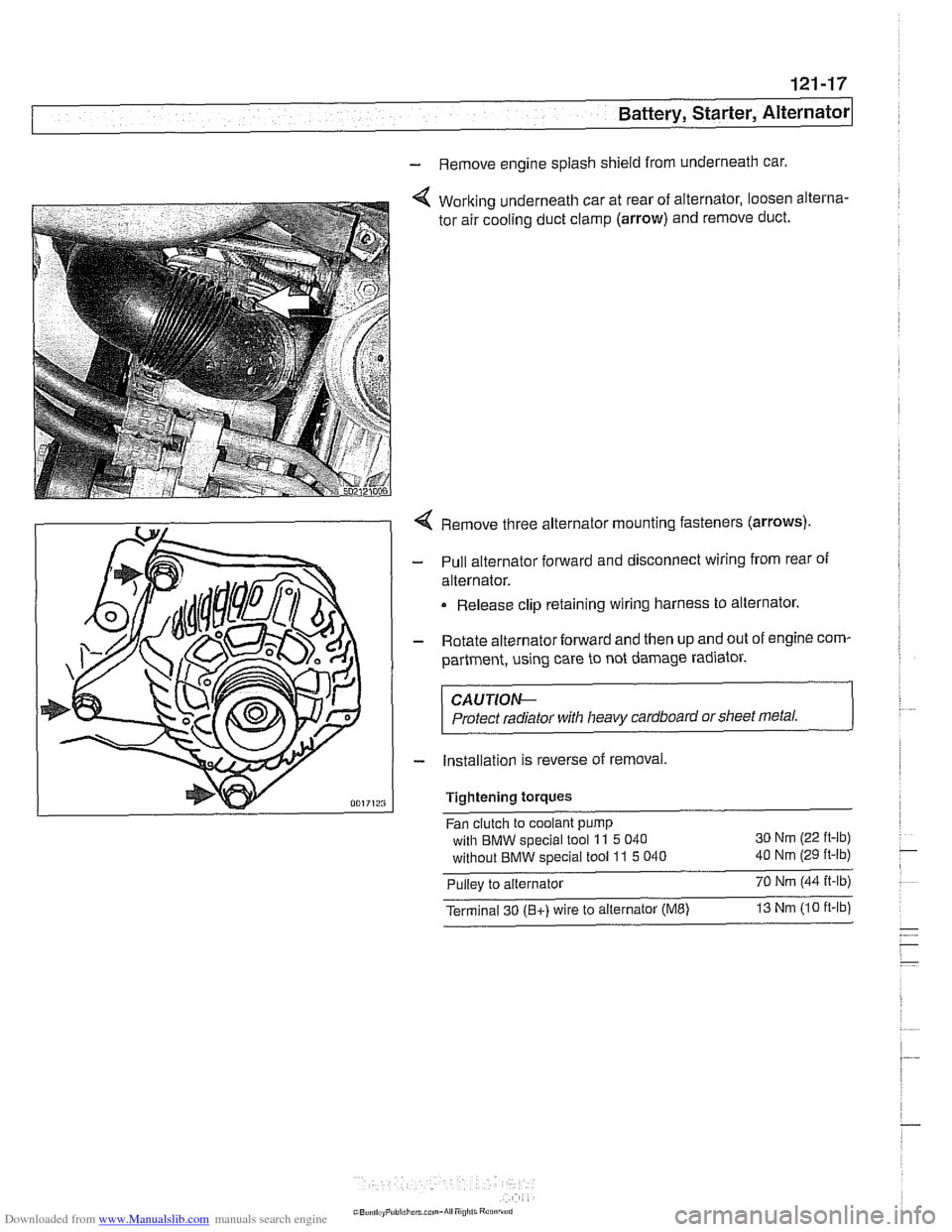
Working underneath car at rear of alternator, loosen alterna-
tor air cooling duct clamp
(arrow) and remove duct.
Remove three alternator mounting fasteners
(arrows)
Pull alternator forward and disconnect wiring from rear of
alternator.
Release clip retaining wiring harness to alternator.
Rotate alternator forward and then up and out of engine com-
partment, using care to not damage radiator.
CAUTIOe
Protect radiator with heavy cardboard or sheet metal.
Installation is reverse of removal,
Tightening
torques
Fan clutch to coolant pump
with BMW special tool
11 5 040 30
Nm (22 ft-lb)
without BMW special tool 11 5 040 40 Nm (29 ft-lb)
Pullev to alternator 70 Nm 144 it-lb) -,
Terminal 30 (Bt) wire to alternator (ME) 13 Nm 110 ft-lb