rear BMW 525i 1997 E39 Repair Manual
[x] Cancel search | Manufacturer: BMW, Model Year: 1997, Model line: 525i, Model: BMW 525i 1997 E39Pages: 1002
Page 397 of 1002
Downloaded from www.Manualslib.com manuals search engine
Fuel Injection 1
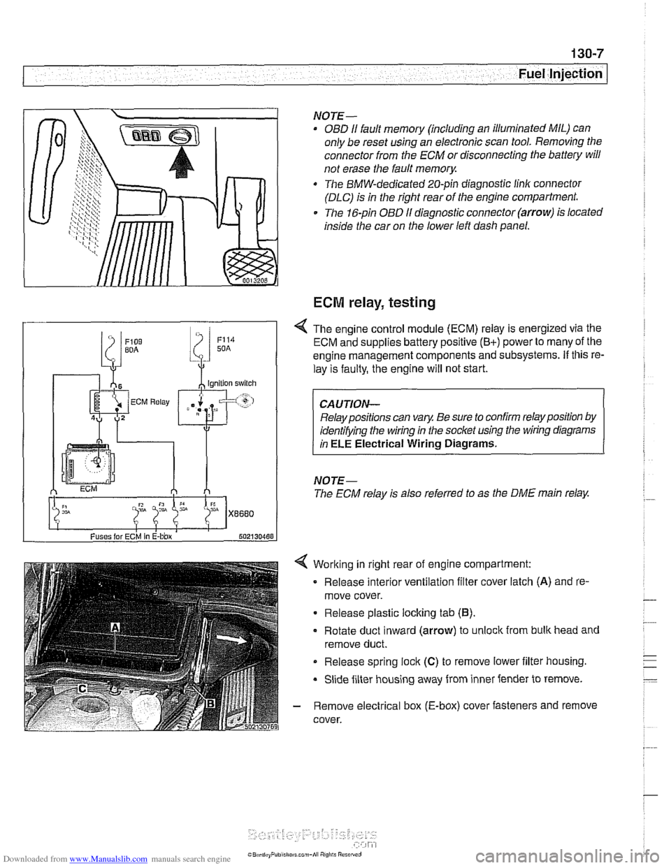
Working in right rear of engine compartment:
Release interior ventilation filter cover latch
(A) and re-
move cover.
Release plastic locking tab
(6).
Rotate duct inward (arrow) to unlock from bulk head and
remove duct.
Release spring
lock (C) to remove lower iilter housing.
Slide filter housing away from inner fender to remove.
- Remove electrical box (E-box) cover fasteners and remove
cover.
NOTE-
OBD I1 fault memory (including an illuminated MIL) can
only be reset using an electronic scan tool. Removing the
connector from the ECM or disconnecting the battery will
not erase the fault
memory.
The BMW-dedicated 20-pin diagnostic linlc connector
(DLC) is in the right rear of the engine compartment.
The 16-pin OBD
I1 diagnostic connector (arrow) is located
inside the car on the lower left dash panel.
ECM relay, testing
Fuses lor ECM In E-bbx 502130488
4 The engine control module (ECM) relay is energized via the
ECM and supplies battery positive
(B+) power to many of the
engine management components and subsystems.
If this re-
lay is faulty, the engine will not start.
Relay positions can vary. Be sure to confirm relay position by
identifying the wiring in the socket using the wiring diagrams
in
ELE Electrical Wiring Diagrams.
NOTE-
The ECM relay is also referred to as the DME main relay.
Page 406 of 1002
Downloaded from www.Manualslib.com manuals search engine
I Fuel Injection
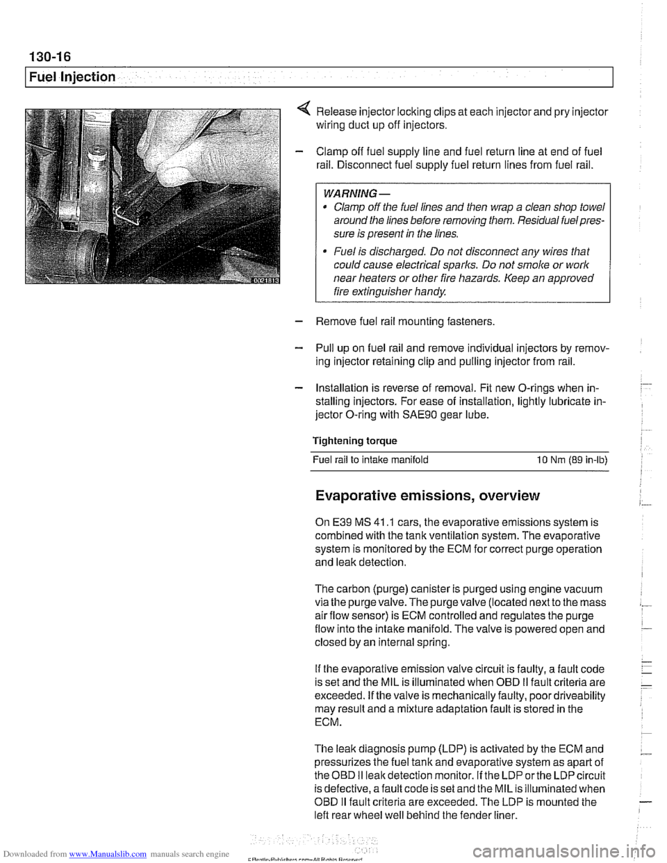
Release injector locking clips at each injector and pry injector
wiring duct up off injectors.
Clamp off fuel supply line and fuel return line at end of fuel
rail. Disconnect fuel supply fuel return lines from fuel rail.
WARNING -
Clamp off the fuel lines and then wrap a clean shop towel
around the lines before removing them. Residual
fuelpres-
sure is present in the lines.
Fuel is discharged. Do not disconnect any wires that
could cause electrical
sparks. Do not smoke or work
near heaters or other fire hazards. Keep an approved
I fire extinguisher handy. I
- Remove fuel rail mounting fasteners
- Pull up on fuel rail and remove individual injectors by remov-
ing injector retaining clip and pulling injector from rail.
- Installation is reverse of removal. Fit new O-rings when in-
stalling injectors. For ease of installation, lightly lubricate in-
jector O-ring with
SAE9O gear lube.
Tightening torque Fuel rail to
intake manifold 10 Nm (89 in-lb)
Evaporative emissions, overview
On E39 MS 41 .I cars, the evaporative emissions system is
combined with the tank ventilation system. The evaporative
system is monitored by the ECM for correct purge operation
and leak detection.
The carbon (purge) canister is purged using engine vacuum
via the
purgevalve.The purgevalve (located nextto the mass
airflow sensor) is ECM controlled and regulates the purge
flow into the intake manifold. The valve is powered open and
closed by an internal spring.
If the evaporative emission valve circuit is faulty, a fault code
is set and the MIL is illuminated when OBD
II fault criteria are
exceeded. If the valve is mechanically faulty, poor driveability
may result and a mixture adaptation fault is stored in the
ECM.
The leak diagnosis pump (LDP) is activated by the ECM and
pressurizes the fuel tank and evaporative system as apart of
theOED I1 leakdetection monitor. If the LDP orthe LDP circuit
is defective, afault code is set and the MIL is illuminated when
OBD
I1 fault criteria are exceeded. The LDP is mounted the
left rear wheel well behind the fender liner.
Page 407 of 1002
Downloaded from www.Manualslib.com manuals search engine
Fuel Injection 1
NOTE-
The 1998 5281' with MS 41.1 requires a barometric pressure
sensor input signal for activation of the
LDP check. This sen-
sor is located on the passenger side strut tower
fo~lard of
ABS/ASC hydraulic unit.
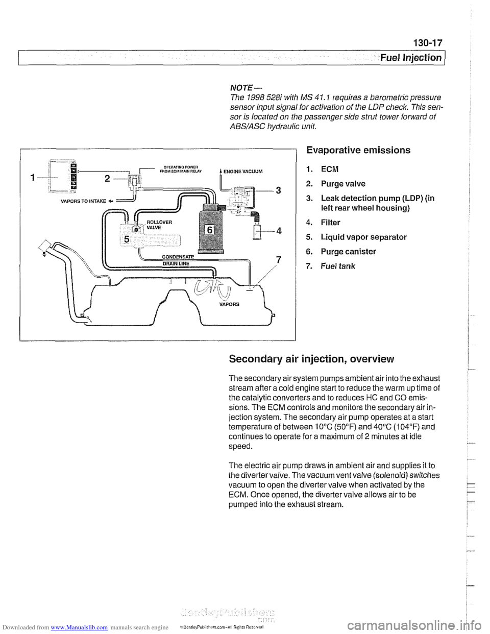
Evaporative emissions
1. ECM
2. Purge valve
3. Leak detection pump (LDP) (in
lefl rear wheel housing)
4. Filter
5. Liquid vapor separator
6. Purge canister
7. Fuel tank
Secondary air injection, overview
The secondary air system pumps ambient air into the exhaust
stream afler a cold engine start to reduce the warm up time of
the catalytic converters and to reduces HC and CO emis-
sions. The ECM controls and monitors the secondary air in-
jection system. The secondary air pump operates at a start
temperature of between 10°C (50°F) and 40°C (104°F) and
continues to operate for a maximum of
2 minutes at idle
speed.
The electric air pump draws in ambient air and supplies it to
the divertervalve. The vacuum ventvalve (solenoid) switches
vacuum to open the divertervalve when activated by the
ECM. Once opened, the diverter valve allows air to be
pumped into the exhaust stream.
Page 410 of 1002
Downloaded from www.Manualslib.com manuals search engine
I Fuel Injection
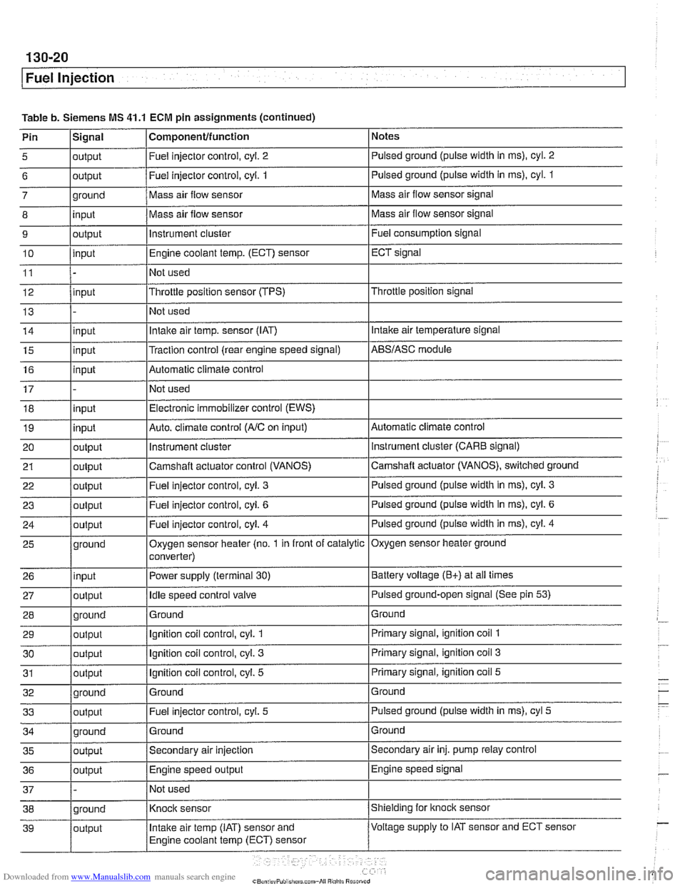
Table b. Siemens MS 41.1 ECM pin assignments (continued)
Pin
l~iqnal I Componentlfunction 1 Notes I - I I
5 loutput I Fuel injector control, cyl. 2 I Pulsed ground (pulse width in ms), cyl. 2 I I I
6 loutput /Fuel injector control, cyi. 1 I Pulsed ground (pulse width in ms), cyl. 1
I I I
14 linput I Intake air temp. sensor (IAT) I Intake air temperature signal
- 7
8
9
10
11
12
13
ground
input
output
input
input
15
16
17 18
19
20
21
22
I - I I
35 loutput /Secondary air injection ISecondary air inj. pump relay control
25
26
27
28
29
30
31
32
33
36
/output I Engine speed output IEngine speed signal
Mass air flow sensor
Mass air flow sensor
instrument cluster
Engine coolant
temp.
(ECT) sensor
Not used
Throttle position sensor (TPS)
Not used
input
input
input
input
output
output
out~ut
37 1 - /Not used I
Mass air flow sensor signal
Mass air flow sensor signal
Fuel consumption signal
ECT signal
Throttle position signal
ground
input
output
ground
output
output
output
ground
output
Traction control (rear engine speed signal) Automatic climate control
Not used Electronic immobilizer control (EWS)
Auto. climate control
(AIC on input)
instrument
cluster
Camshaft actuator control (VANOS)
Fuel iniector control, cvl.
3
AES/ASC module
Automatic climate control instrument cluster (CARE signal)
Camshaft actuator (VANOS), switched ground
Pulsed ground (pulse width in
ms), cyl. 3
Oxygen sensor heater (no. 1 in front of catalytic
converter)
Power supply (terminal
30)
Idle speed control valve
Ground
Ignition coil control, cyl.
1
Ignition coil control, cyl. 3
Ignition coil control, cyl. 5
Ground Fuel injector control, cyl.
5
Oxygen sensor heater ground
Battery voltage
(E+) at all times
Pulsed ground-open signal (See pin
53)
Ground
Primary signal, ignition coil
1
Primary signal, ignition coil 3
Primary signal, ignition coil 5
Ground
Pulsed ground (pulse width in ms), cyl
5
Page 413 of 1002
Downloaded from www.Manualslib.com manuals search engine
- -.
Fuel Injection
SIEMENS MIS 42.0 AND 43.0
When system faults are detected, a diagnostic trouble code
(DTC) is stored in the engine control module (ECM). The MIL
also illuminates
if an emissions-related fault is detected.
When faults arise, or
if the malfunction indicator lamp (MIL) is
illuminated, begin troubleshooting by connecting BMW ser-
vice tester
DISplus, MoDiC, GTI or equivalent scan tool. The
capabilities of OBD
II software has the potential to save hours
of diagnostic time and to help avoid incorrect component re-
placement and possible damage to system components.
CAUTION-
* The tests in this section may set fault codes (DTCs) in tlie
ECM and illuminate the MIL. After all testing is completed,
access and clear DTC fault
memory using an OBD I/ or
BMW compatible scan tool. See
OBD On-Board Diag-
nostics.
Only use a
dgital multimeter for electrical tests.
Relay positions can vary. Be sure to confirm
relayposi-
tion by identifying the wiring in the socket using the wir-
ing diagrams found in
ELE Electrical Wiring
Diagrams.
NOTE-
- OBD I1 fault memory. (including an illuminated MIL! can
only be reset using the special scan tool. Removing the
connector from the ECM or disconnecting the battery will
not erase the fault memory.
The BMW-dedicated 20-pin diagnostic
linlc connector
(DLC) is in the right rear of the engine compartment The
20-pin DLC is discontinued on models after
6/2000.
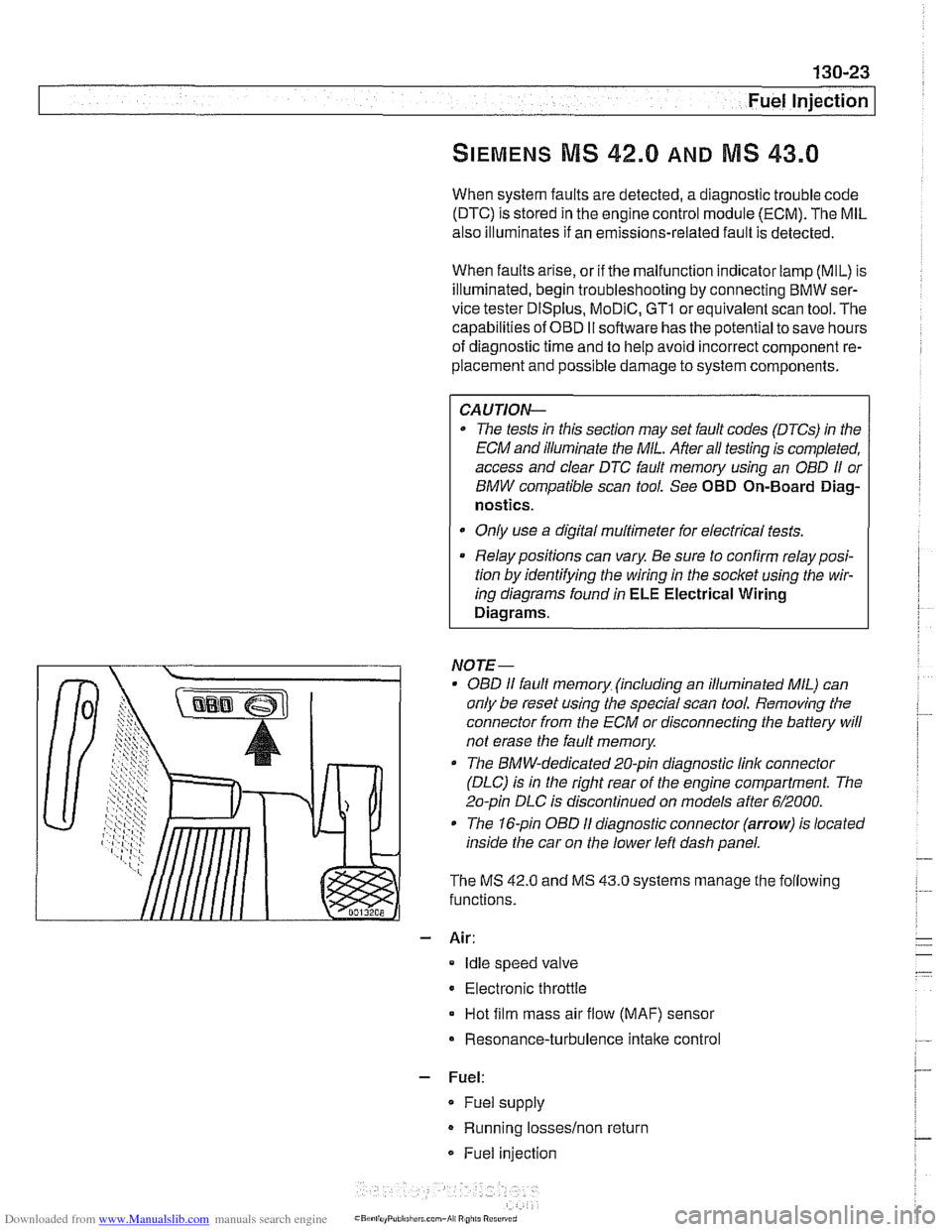
The 1 &pin OBD I1 diagnostic connector (arrow) is located
inside the car on the lower left dash panel.
The MS
42.0 and MS 43.0 systems manage the following
functions.
- Air:
Idle speed valve
Electronic throttle
Hot film mass air flow (MAF) sensor
Resonance-turbulence intake control
- Fuel:
* Fuel supply
Running losseslnon return
Fuel injection
Page 417 of 1002
Downloaded from www.Manualslib.com manuals search engine
-
Fuel Injection
ECM relay, testing
The engine control module (ECM) relay is energized via the
ECM and supplies battery positive
(Bc) power to many of the
engine management components and subsystems. If this re-
lay is faulty, the engine will not start.
NOTE-
The ECM relay is also referred to as the DME main relay
ECM relay powers:
ECM
Ignition coils
* Fuel injection
Evaporative leak detection pump
Idle air actuator
- Camshaft sensors Evaporative emissions valve
Hot film mass air flow sensor
Fuel pump relay
Oxygen sensor heaters
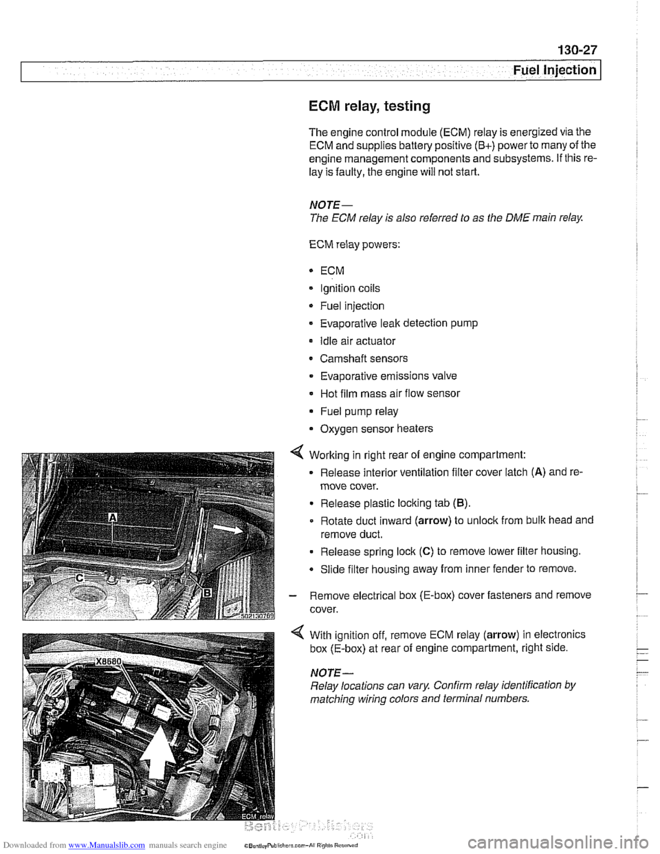
4 Working in right rear of engine compartment:
Release interior ventilation filter cover latch
(A) and re-
move cover.
Release plastic locking tab
(B).
Rotate duct inward (arrow) to unlock from bulk head and
remove duct.
Release spring lock
(C) to remove lower filter housing.
Slide filter housing away from inner fender to remove.
- Remove electrical box (E-box) cover fasteners and remove
cover.
With ignition off, remove ECM relay (arrow) in electronics
box (E-box) at rear of engine compartment, right side.
NOTE-
Relay locations can vary Confirm relay identification by
matching wiring colors and terminal numbers.
Page 420 of 1002
Downloaded from www.Manualslib.com manuals search engine
Fuel Injection
Engine coolant temperature
(ECT) sensor,
testing and replacing
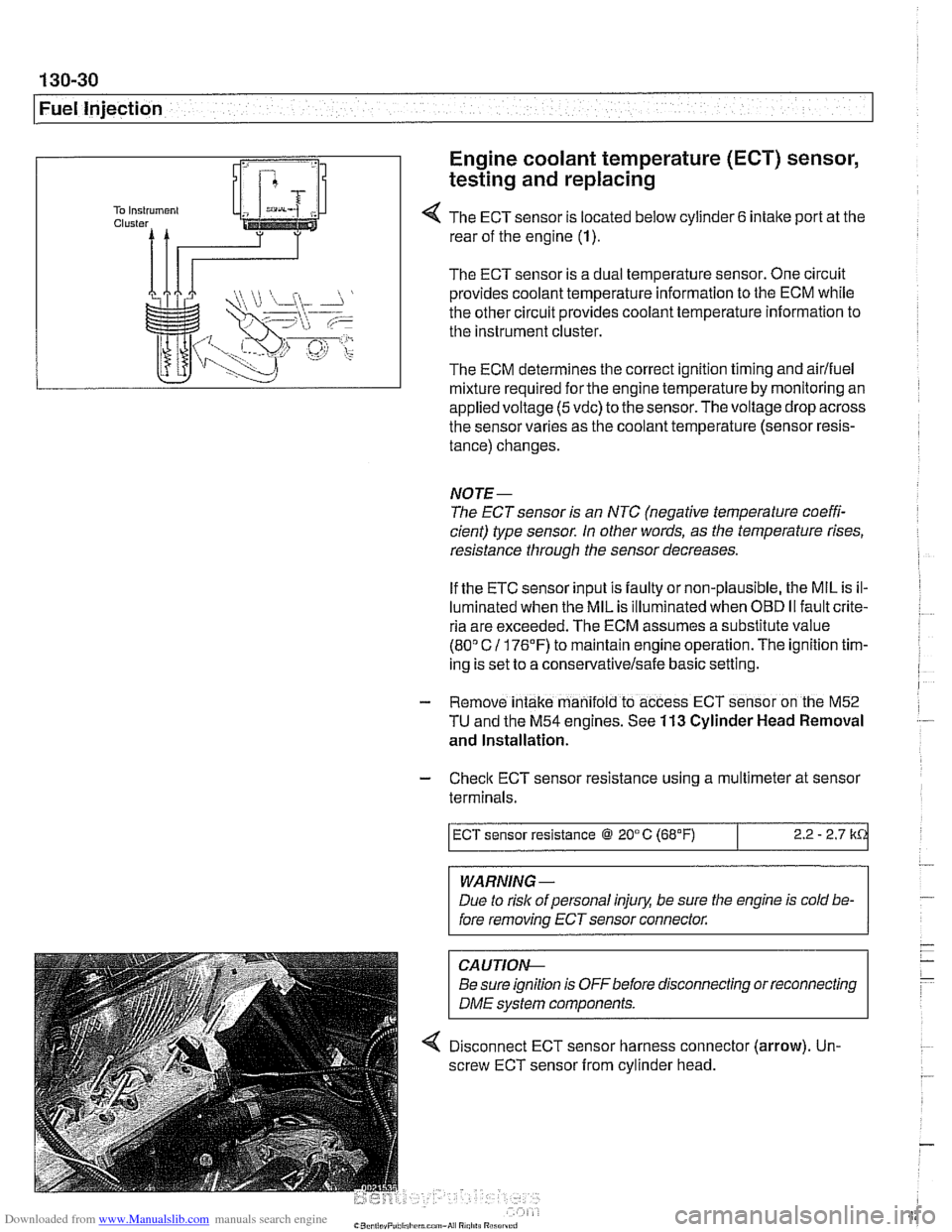
4 The ECT sensor is located below cylinder 6 intake port at the
rear of the engine (1).
The ECT sensor is a dual temperature sensor. One circuit
provides coolant temperature information to the ECM while
the other circuit provides coolant temperature information to
the instrument cluster.
The ECM determines the correct ignition timing and airlfuel
mixture required
forthe engine temperature by monitoring an
appliedvoltage
(5vdc) to the sensor.Thevoltage drop across
the sensor varies as the coolant temperature (sensor resis-
tance) changes.
NOTE-
The ECT sensor is an NTC (negative temperature coeffi-
cient) type sensor. In other words, as the temperature rises,
resistance through the sensor decreases.
If the ETC sensor input is faulty or non-plausible, the MIL is il-
luminated when the MIL is illuminated when
OED II fault crite-
ria are exceeded. The ECM assumes a substitute value
(80" C 11 76'F) to maintain engine operation. The ignition tim-
ing is set to a
conservativelsafe basic setting.
- Remove intake manifold to access ECT sensor on the M52
TU and the M54 engines. See 113 Cylinder Head Removal
and Installation.
- Check ECT sensor resistance using a multimeter at sensor
terminals.
WARNING -
Due to rislc of personal injury, be sure the engine is cold be-
fore removing ECT sensor connector.
ECT sensor resistance @ 20°C (68°F)
CAUTIOI\C
Be sure ignition is OFFbefore disconnecting or reconnecting
DME svstem components.
2.2 - 2.7 k
4 Disconnect ECT sensor harness connector (arrow). Un-
screw ECT sensor from cylinder head.
Page 436 of 1002
Downloaded from www.Manualslib.com manuals search engine
130-46
Fuel Injection
When system faults are detected, a diagnostic trouble code
(DTC) is stored in the engine control module (ECM). The MIL
also illuminates if an emissions-related fault is detected.
When faults arise, or
if the malfunction indicator lamp (MIL) is
illuminated, begin troubleshooting by connecting BMW ser-
vice tester
DISplus. MoDiC, GTI or equivalent scan tool. The
capabilities of
OED II software has the potential to save hours
of diagnostic time and to help avoid incorrect component re-
placement and possible damage to system components.
CA UTIOiU-
The tests in this section may set fault codes (DTCs) in the
ECM and illuminate the MIL. After ail testing is completed,
access and clear DTC fault
memory using an OED I/ or
BMW compatible scan tool. See OBD On-Board Diag-
nostics.
Only use a digital
multimeter for electrical tests.
Relay positions can vary. Be sure to confirm relay
posi-
. tion by identifying the wiring in the socket using the wir-
ing diagrams-found in ~~~~lectrical Wiring
Diagrams.
NOTE-
OED I1 fault memory (including an illuminated MIL) can
only be reset
using~the special scan tool. Removing the
connector from the ECM or disconnecting the battery will
not erase the fault
memory.
The BMW-dedicated 20-pin diagnostic link connector
(DLC) is in the right rear of the engine compartment.
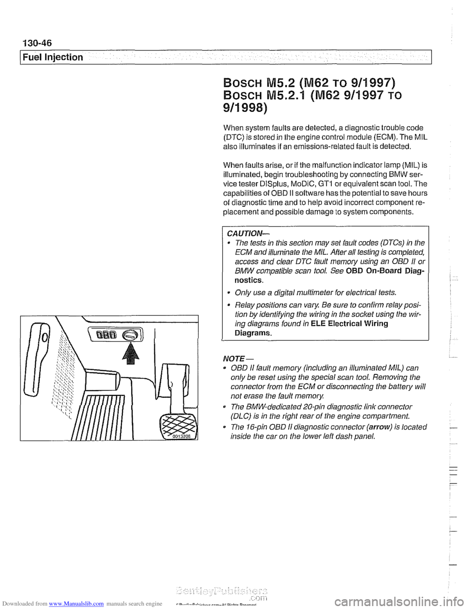
The 16-pin OBD
I1 diagnostic connector (arrow) is located
inside the car on
the lower left dash panel.
Page 439 of 1002
Downloaded from www.Manualslib.com manuals search engine
- Fuel Injection
ECM relay, testing
The engine control module (ECM) relay is energized via the
ECM and supplies battery positive
(B+) power to many of the
engine
management components and subsystems. If this re-
lay is faulty, the engine will not start.
CAUTIOI\C
Relay positions can vary. Be sure to confirm relay position by
identifying the wiring
in the socket using the wiring diagrams
in ELE Electrical Wiring Diagrams.
NOTE-
The ECM relay is also referred to as the DME main relay.
ECM relay powers:
* ECM
Ignition coils
Fuel injection
Evaporative leak detection pump
(5.2.1 only)
Idle air actuator
Camshaft sensors Evaporative emissions valve
Hot film mass air flow sensor
Fuel pump relay
Oxygen sensor heaters
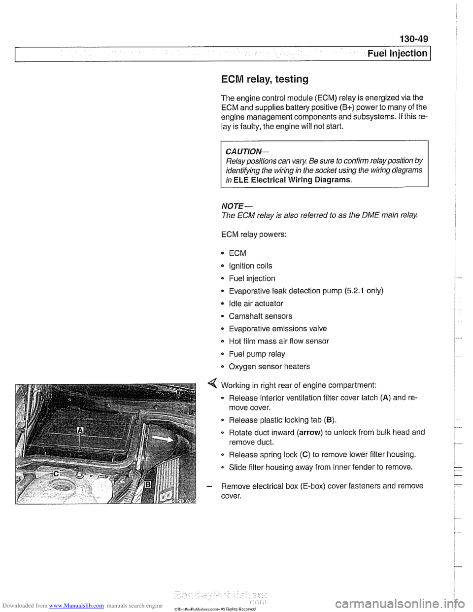
4 Working in right rear of engine compartment:
Release interior ventilation filter cover latch
(A) and re-
move cover.
Release plastic locking tab
(B).
Rotate duct inward (arrow) to unloclc from bulk head and
remove duct.
0 Release spring lock (C) to remove lower filter housing.
Slide filter housing away from inner fender to remove.
- Remove electrical box (E-box) cover fasteners and remove
cover.
Page 440 of 1002

Downloaded from www.Manualslib.com manuals search engine
130-50
Fuel Injection
Bosch M5.2
ECM relay
1 HoL al ail iirnel XOL a1 ail limes
i--[-----i F109 (BOA) electronics I L.$.....: .I:
ECM relay . . . . . . . . . ,
8,s
:,
6 1 .. ... ~~.~~. . ...... .-, Engine control ii~~-~.~~..~ ........ ~~~~~~.~~~~:. module relay -;I
Of?
,c,;,,,
< With ignition off, remove ECM relay (arrow) in electronics
box (E-box) at right rear of engine compartment.
NOTE-
Relay locations can vary. Conh relay identification by
matcliing wiring colors and terminal numbers.
4 Check for voltage at terminal 6 of main relay socket (30-red
wire). On M5.2 cars also check for battery voltage at terminal
8.
. . . . . . . . . ,
If battery voltage is present, continue testing
.
If battery voltage is not present, check large red wire(s) in
relay socltet. See
ELE Electrical Wiring Diagrams.
%P,,tt
- Reinstall relay and turn ignition on. Gain access to underside
of relay socket and
checlc for ground at terminal 4 (85-brown
wire).
. . . . . . . . . . . . - - - - - - - - - . - - - . . l ,,-. ; Engine i f .: , ; Fuse carrier .,A . :engine /;is? /control L.!.!! .... 1.: ...... !.::..! I lij :module electronics If
ground is present, continue testing
If ground is not present, signal from ECM is missing. Checic
wire between ECM and relay.
4 With ignition on and relay installed, check for battery voltage
at terminal
2 (87-redlwhite wire). On M5.2.1 cars also checlc
for battery voltage at terminal 5.
If battery voltage is present, relay has energized and is
functioning correctly.
If battery voltage is not present and all earlier tests are OK,
relay is faulty and should be replaced.