ECO BMW 525i 1997 E39 Repair Manual
[x] Cancel search | Manufacturer: BMW, Model Year: 1997, Model line: 525i, Model: BMW 525i 1997 E39Pages: 1002
Page 180 of 1002
Downloaded from www.Manualslib.com manuals search engine
/cylinder Head and Valvetrain
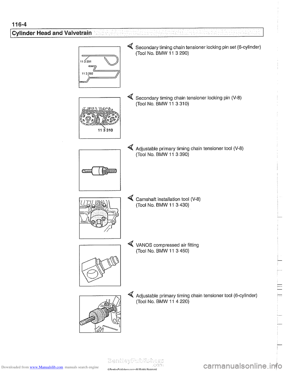
Secondary timing chain tensioner locking pin set (6-cylinder)
- 4 Secondary timing chain tensioner locking pin (V-8)
(Tool No. BMW
11 3 310)
4 Adjustable primary timing chain tensioner tool (V-8)
(Tool No. BMW
11 3 390)
4 Camshaft installation tool (V-8)
(Tool No.
BMW 11 3 430)
4 VANOS compressed air fitting
7 (Tool No. BMW 11 3 450)
Adjustable primary timing chain tensioner tool (6-cylinder) (Tool No. BMW
11 4 220)
Page 181 of 1002
Downloaded from www.Manualslib.com manuals search engine
11 6-5
I Cylinder Head and valvetrain1
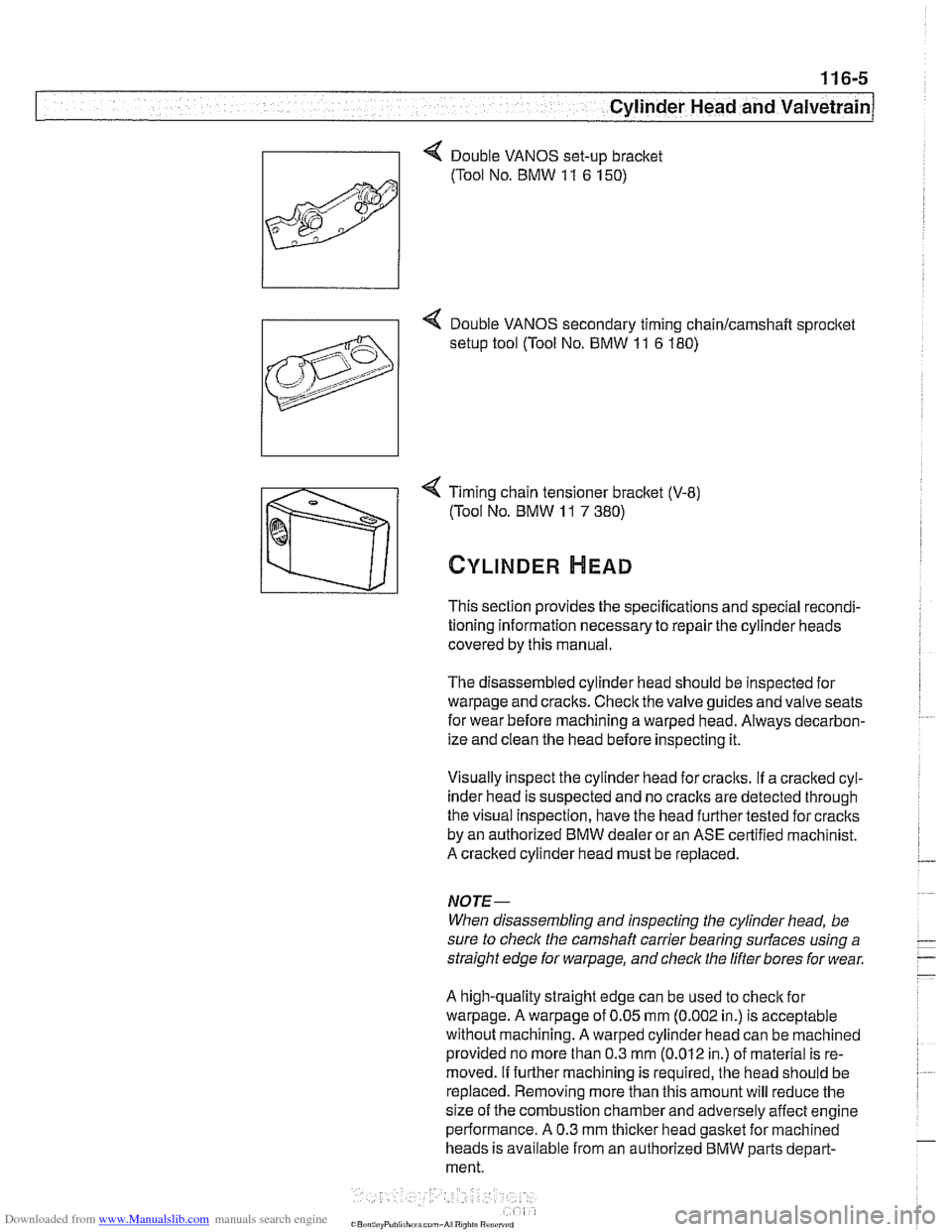
4 Timing chain tensioner bracket (V-8)
(Tool No. BMW
11 7 380)
CYLINDER HEAD
This section provides the specifications and special recondi-
tioning information necessary to repair the cylinder heads
covered by this manual.
The disassembled cylinder head should be inspected for
warpage and cracks. Check the valve guides and valve seats
for wear before machining a warped head. Always decarbon-
ize and clean the head before inspecting it.
Visually inspect the cylinder head for craclts.
If a cracked cyl-
inder head is suspected and no
craclts are detected through
the visual Inspection, have the head further tested for cracks
by an authorized BMW dealer or an ASE certified machinist.
A cracked cylinder head must be replaced.
NOJE-
When disassembling and inspecting the cylinder head, be
sure to
checlc the camshaft carrier bearing surfaces using a
straight edge for
warpage, and check the lifter bores for wear.
A high-quality straight edge can be used to
checlc for
warpage. A warpage of 0.05 mm (0.002 in.) is acceptable
without machining. A warped cylinder head can be machined
provided no more than 0.3
mm (0.012 in.) of material is re-
moved.
If further machining is required, the head should be
replaced. Removing more than this amount will reduce the
size of the combustion chamber and adversely affect engine
performance. A 0.3 mm
thicker head gasket for machined
heads is available from an authorized BMW parts depart-
ment.
Page 182 of 1002
Downloaded from www.Manualslib.com manuals search engine
11 6-6
Cylinder Head and Valvetrain
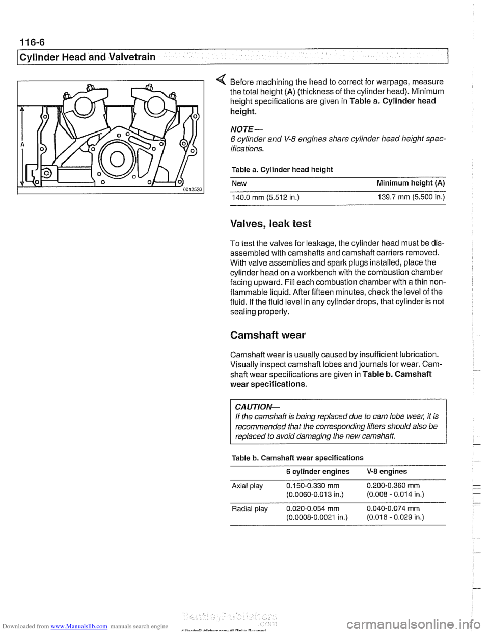
4 Before machining the head to correct for warpage, measure
the total height
(A) (thickness of the cylinder head). Minimum
height specifications are given in Table a. Cylinder head
height.
NOTE-
6 cylinder and V-8 engines share cylinder head height spec-
ifications.
Table a. Cylinder head height
New Minimum height
(A)
140.0 rnrn (5.512 in.) 139.7 rnrn (5.500 in.)
Valves, leak test
To test the valves for leakage, the cylinder head must be dis-
assembled with camshafts and camshaft carriers removed.
With valve assemblies and spark plugs installed, place the
cylinder head on a workbench with the combustion chamber
facing upward. Fill each combustion chamber with a thin non-
flammable liquid. After fifteen minutes, check the level of the
fluid. If the fluid level in any cylinder drops, that cylinder is not
sealing properly.
Camshaft wear
Camshaft wear is usually caused by insufficient lubrication.
Visually inspect camshaft lobes and journals for wear. Cam-
. ~~ shaft wear specifications are given in Table b. Camshaft
wear specifications.
CA UTIOI\C
If the camshaft is being replaced due to cam lobe wear, it is
recommended that the corresponding lifters should also be
replaced to avoid damaging the new camshaft
Table b. Camshaft wear specifications
6 cylinder engines V-8 engines
Axlal play 0.150-0.330 rnrn 0 200-0 360 rnrn - .-
(0.0060-0 013 in.) (0.008 - 0.014 in ) - - Radlal play 0.020-0.054 rnrn 0.040-0.074 rnrn
(0.0008-0.0021 in.) (0.016 - 0.029 in.)
Page 186 of 1002
Downloaded from www.Manualslib.com manuals search engine
Cylinder Head and Valvetrain
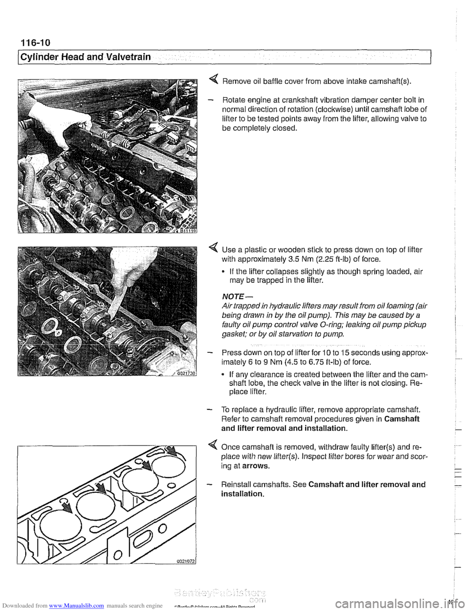
< Remove oil baffle cover from above intake camshaft(s)
- Rotate engine at crankshaft vibration damper center bolt in
normal direction of rotation (clockwise) until camshaft lobe of
lifter to be tested points away from the lifter, allowing valve to
be completely closed.
Use a plastic or wooden stick to press down on top of lifter
with approximately 3.5 Nm
(2.25 ft-ib) of force.
If the lifter collapses slightly as though spring loaded, air
may be trapped in the lifter.
NOTE-
Air trapped in hydraulic lifters may result from oil foaming (air
being drawn
in by the oil pump). This may be caused by a
faulty oil pump control valve O-ring; leaking oil pump pickup
gaslcet; or by oil starvation to pump.
Press down on top of lifter for
10 to 15 seconds uslng approx-
lmately 6 to 9 Nm (4.5 to 6.75 ft-lb) of force.
If anv clearance is created between the lifter and the
cam-
shafi lobe, the check valve in the lifter is not closing. Re-
place lifter.
- To replace a hydraulic lifter, remove appropriate camshaft.
Refer to camshaft removal procedures given in Camshaft
and lifter removal and installation.
Once camshaft is removed, withdraw faulty
lifter(s) and re-
place with new
lifter(s). Inspect lifter bores for wear and scor-
ing at arrows.
- Reinstall camshafts. See Camshaft and lifter removal and
installation.
Page 189 of 1002
Downloaded from www.Manualslib.com manuals search engine
Cylinder Head and Valvetrain
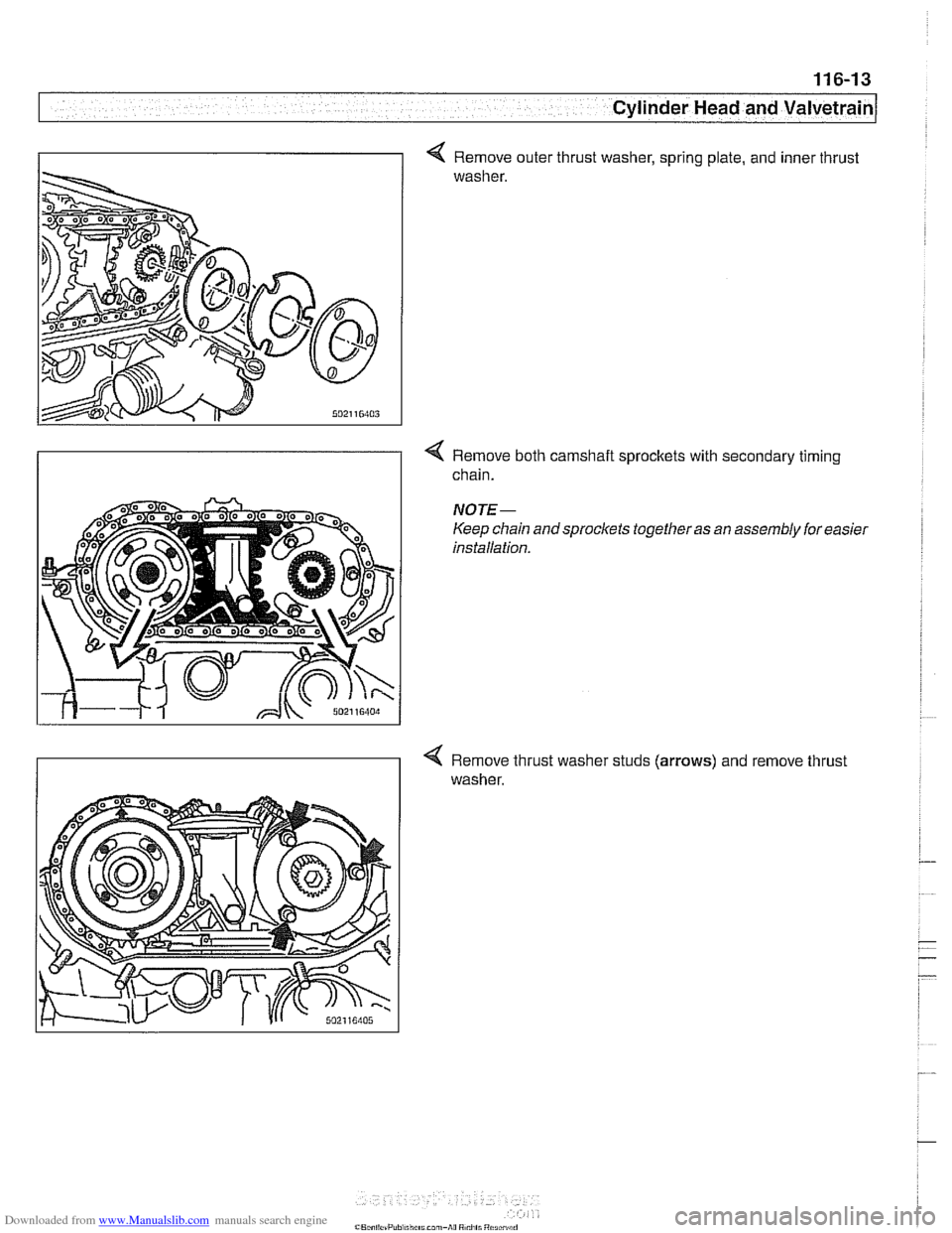
I I < Remove outer thrust washer, sprinq plate, and inner thrust
washer.
4 Remove both camshait sprockets with secondary timing
chain.
NOTE-
Keep chain and sprockets together as an assembly for easier
installation.
< Remove thrust washer studs (arrows) and remove thrust
washer.
Page 190 of 1002
Downloaded from www.Manualslib.com manuals search engine
116-14
I Cylinder Head and Valvetrain
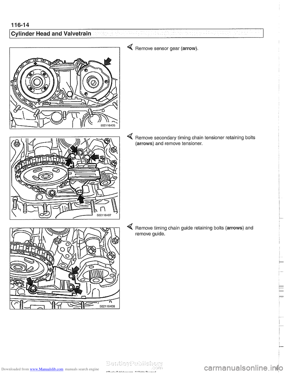
4 Remove sensor gear (arrow).
Remove secondary timing chain tensioner retaining bolts
(arrows) and remove tensioner.
Remove timing chain guide
reta~ning bolts (arrows) and
remove guide.
Page 196 of 1002
Downloaded from www.Manualslib.com manuals search engine
/Cylinder Head and Valvetrain
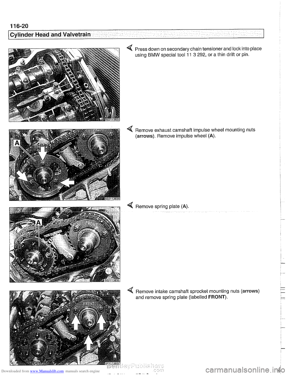
Press down on secondary chain tensionerand loclc into place
using
BMW special tool 11 3 292, or a thin drift or pin.
4 Remove exhaust camshaft impulse wheel mounting nuts
(arrows). Remove impulse wheel (A).
< Remove spring plate (A).
4 Remove intake camshaft sprocket mounting nuts (arrows)
and remove spring plate (labelled
FRONT).
Page 197 of 1002
Downloaded from www.Manualslib.com manuals search engine
I_
-.
Cylinder Head and Valvetrain
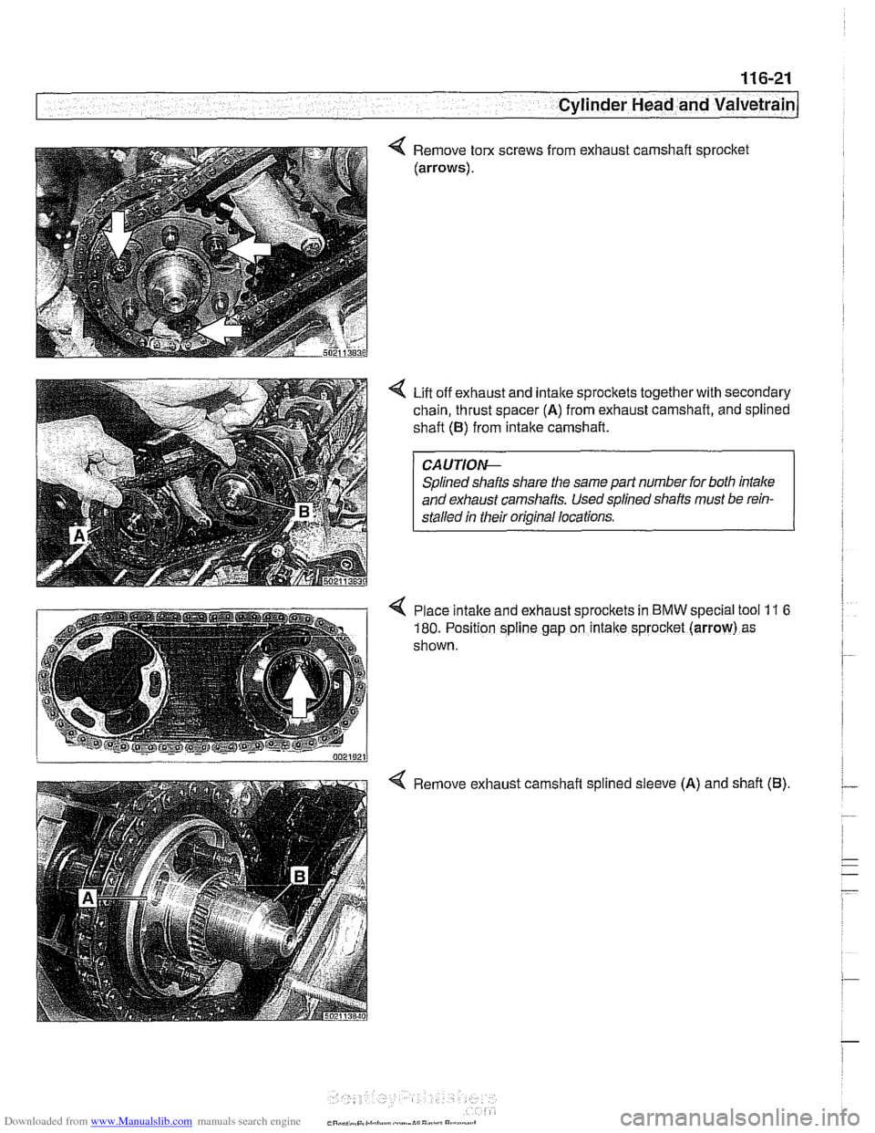
Remove torx
(arrows). screws
from
exhausl
: camshaft : sprocket
Lift off exhaust and intalte sprockets together with secondary
chain, thrust spacer
(A) from exhaust camshaft, and splined
shaft (B) from intake camshaft.
CAUTIOf+
Splined shafts share the same part number for both intake
and exhaust camshafts. Used splined shafts must be rein-
stalled in their
oriqinal locations.
Place intalte and exhaust sprockets in
BMW special tool 11 6
/ 180. Position spline gap on intake sprocket (arrow) as
shown.
4 Remove exhaust camshaft splined sleeve (A) and shaft (B).
Page 198 of 1002
Downloaded from www.Manualslib.com manuals search engine
11 6-22
Cylinder Head and Valvetrain
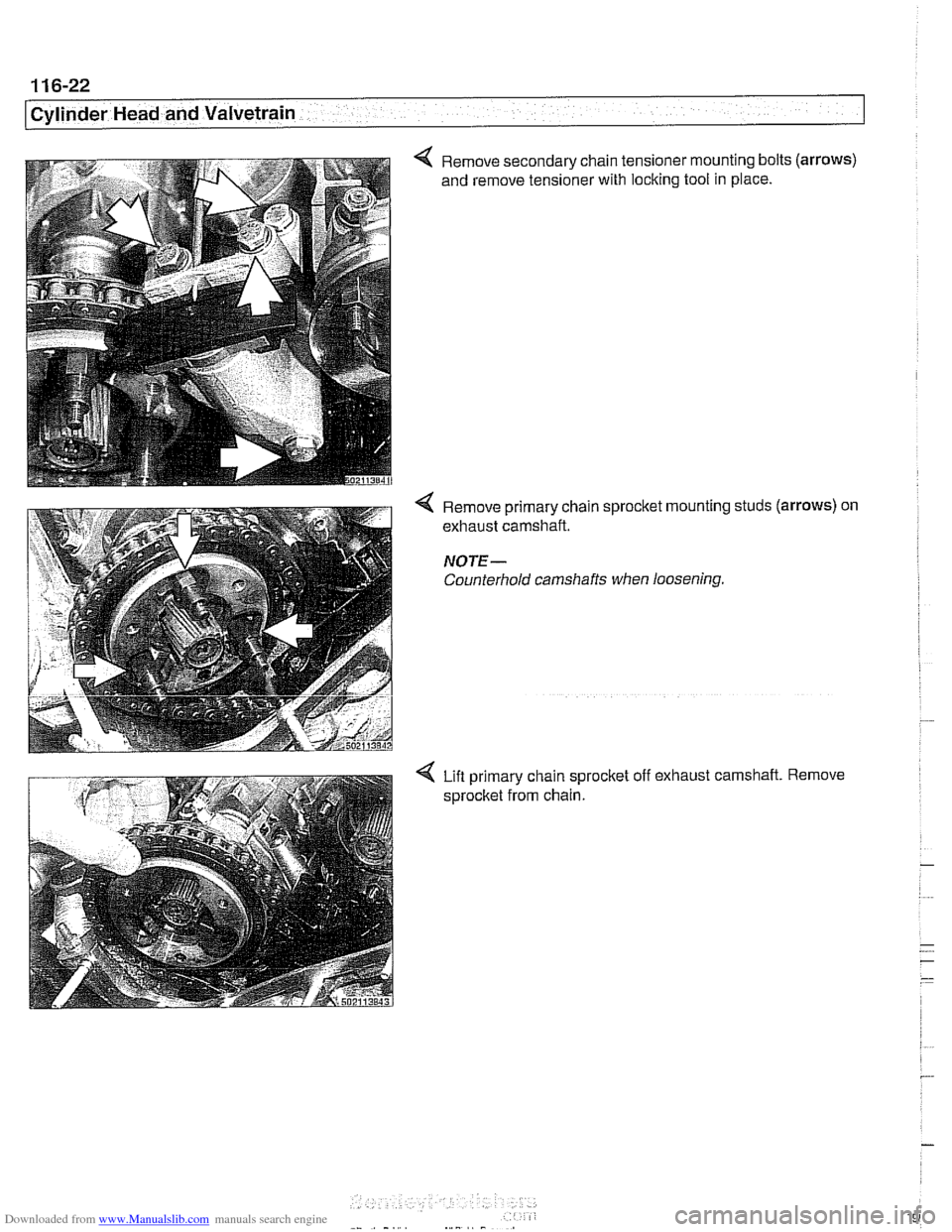
Remove secondary chain tensioner mounting bolts (arrows)
and remove tensioner with locking tool in place.
Remove primary chain sprocket mounting studs
(arrows) on
exhaust camshaft.
NOTE-
Counterhold camshafts when loosening.
Lifl primary chain sprocket off exhaust camshaft. Remove
sprocket from chain.
Page 204 of 1002
Downloaded from www.Manualslib.com manuals search engine
11 6-28
Cylinder Head and Valvetrain
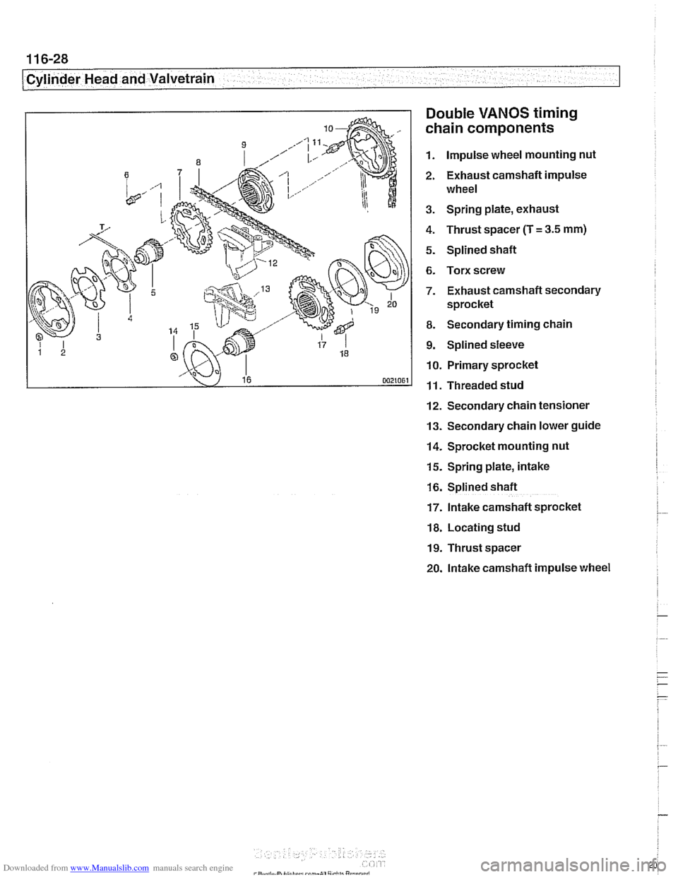
Double
VANOS timing
chain components
1. Impulse wheel mounting nut
2. Exhaust camshaft impulse
wheel
3. Spring plate, exhaust
4. Thrust spacer (T
= 3.5 mm)
5. Splined shaft
6. Torx screw
7. Exhaust camshaft secondary
sprocket
8. Secondary timing chain
9. Splined sleeve
10. Primary sprocket
11. Threaded stud
12. Secondary chain tensioner
13. Secondary chain lower guide
14. Sprocket mounting nut
15. Spring plate, intake
16. Splined shaft
17. Intake camshaft sprocket
18. Locating stud
19. Thrust spacer
20. lntake camshaft impulse wheel