ECO BMW 525i 1997 E39 Workshop Manual
[x] Cancel search | Manufacturer: BMW, Model Year: 1997, Model line: 525i, Model: BMW 525i 1997 E39Pages: 1002
Page 294 of 1002
Downloaded from www.Manualslib.com manuals search engine
(camshaft Timing Chain
- To install lower timing case cover:
- Clean cover and cylinder block sealing surfaces
Use new
gaskets and coolant pipe O-ring.
Remove timing chain cover dowel pins from engine block.
Drive timing cover dowels in until they just protrude slightly
from sealing surface.
Apply a small bead of silicon sealer (Three Bond 1209
63
or equivalent) to corners of cylinder head where timing
cover meets cylinder head and engine block.
Tap cover into position until firmly seated.
lnstall all bolts hand tight, including two Torx bolts from
above.
Install secondary chain lower guide.
Tighten cover mounting bolts alternately and in stages.
Tightening torque
Lower timing cover to cylinder
bloclc (M6) 10 Nrn (89 in-lb)
- Install oil pan with new gasket. See 119 Lubrication Sys-
tem.
Tightening torque
Oil pan
to engine bloclc (M6)
8.8 grade
10.9 grade 10 Nrn (89 in-lb)
12 Nm
(9 ft-lb)
- Align damper assembly with lteyway and tap into place. In-
sert new center bolt with washer.
CAUTION-
Inspect woodruff key for damage before installing hub
assembly.
- Attach special tools 11 8 20011 1 8 190 to damper assembly.
Counterhold damper with
11 8 190 while tightening center
bolt.
CAUTION-
Do not use BMW special tool 1 I 2 300 to hold crankshaft
stationary to tighten cranl(shaft hub center bolt. Use only
the special tools specified, or equivalent hub holding tool.
Have a second person hold special tool
11 8 190 while
tightening center crankshaft bolt.
Tightening torque Crankshaft hub to crankshaft 410 Nrn
(300
ft-lb)
Page 296 of 1002
Downloaded from www.Manualslib.com manuals search engine
11 7-60
Camshaft Timing Chain
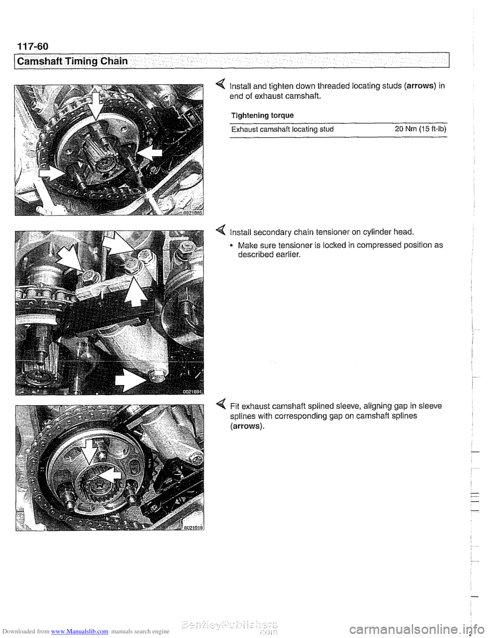
< Install and tighten down threaded locating studs (arrows) in
end of exhaust camshaft.
Tightening torque Exhaust camshaft locating
stud 20 Nrn (15 ft-lb)
4 Install secondary chain tensioner on cylinder head.
- Make sure tensioner is locked in compressed position as
described earlier.
Fit exhaust camshaft splined sleeve, aligning gap in sleeve
splines with corresponding gap on
camshaft splines
(arrows).
Page 297 of 1002
![BMW 525i 1997 E39 Workshop Manual Downloaded from www.Manualslib.com manuals search engine
- Camshaft Timing chain]
< Slide splined shaft onto exhaust camshaft, aligning larger
tooth with corresponding gap of splined sleeve (arr](/img/1/2822/w960_2822-296.png "BMW 525i 1997 E39 Workshop Manual Downloaded from www.Manualslib.com manuals search engine
- Camshaft Timing chain]
< Slide splined shaft onto exhaust camshaft, aligning larger
tooth with corresponding gap of splined sleeve (arr")
Downloaded from www.Manualslib.com manuals search engine
- Camshaft Timing chain]
< Slide splined shaft onto exhaust camshaft, aligning larger
tooth with corresponding gap of splined sleeve (arrows).
Slide splined shaft in further until
3 small or elongated slots
in splined sleeve are centered to
3 threaded holes in
sprocket.
4 Place intake and exhaust sprocltets in BMW special tool 11 6
180. Position spline gap on intalte sprocket (arrow) as shown
and place secondary chain on sprocltets.
< Carefully remove chain and sprockets from tool and slide
onto camshafts. Align gap in
intalte sprocket splines with cor-
responding gap in camshaft splines (arrow).
CAUTION-
Do not alterposltion ofsprocl(ets with respect to chain when
removing from
specfa1 tool 1 1 6 180.
4 Slide splined shaft onto intake camshaft until approx. 1 mm
(0.04 in.) of splines can still be seen.
Page 299 of 1002
Downloaded from www.Manualslib.com manuals search engine
Camshaft Timing chain1
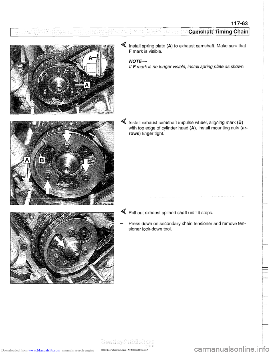
4 lnstall spring plate (A) to exhaust camshaft. Make sure that
F mark is visible.
NOTE-
If F mark is no longer visible, install spring plate as shown
Install exhaust camshaft impulse wheel, aligning
mark (B)
with top edge of cylinder head (A). Install mounting nuts (ar-
rows)
finger tight.
4 Pull out exhaust splined shaft until it stops
- Press down on secondary chain tensioner and remove ten-
sioner lock-down tool.
Page 333 of 1002
![BMW 525i 1997 E39 Workshop Manual Downloaded from www.Manualslib.com manuals search engine
-- . - .. . - Lubrication system]
- Remainder of installation is reverse of removal.
Replace self-locking nuts when reinstalling front](/img/1/2822/w960_2822-332.png "BMW 525i 1997 E39 Workshop Manual Downloaded from www.Manualslib.com manuals search engine
-- . - .. . - Lubrication system]
- Remainder of installation is reverse of removal.
Replace self-locking nuts when reinstalling front")
Downloaded from www.Manualslib.com manuals search engine
-- . - .. . - Lubrication system]
- Remainder of installation is reverse of removal.
Replace self-locking nuts when reinstalling front suspen-
sion components.
Use new oil dipstick tube sealing O-ring.
After adding engine oil, start and run engine. Raise engine
speed to 2,500 rpm until oil pressure warning light goes out
(about 5 seconds).
NOTE-
BMW does not specify a front end alignment following this
procedure.
Tightening torques Front subfrarne to body rail
(M12, use new bolts)
8.8 grade
10.9 grade
12.9 grade 77 Nrn
(57 ft-lb)
105 Nrn (77 ft-lb)
110 Nrn (81 ft-lb)
Stabilizer bar link to stabilizer bar
65 Nrn (48 ft-lb)
Steering shaft universal joint clamping bolt
(use new bolt)
19 Nrn (14 it-lb)
Lower oil pan, removing and installing (V-8)
- The V-8 engine is equipped with a 2-piece oil pan. The fas-
teners in
V-8 engine oil pump assembly, including the
sprocket retaining nut, are known to loosen and fall off into
the oil pan. Be sure to install these fasteners with Loctite
O
or equivalent thread locking product and torque to specifica-
tions.
CAUTION-
It is recommended that the oil pump retaining bolts and oil
pump drive sprocket retaining nut tightening torque be
checkedany time the
oilpan is removed.
- Raise car and place securely on jack stands.
WARNING-
Make sure the car is stable and well supported at all times.
Use a professional automotive lift
orjack stands designed for
- Remove splash shield from under engine.
- Drain engine oil
- On cars with automatic transmission, remove ATF cooler line
brackets from oil pan.
Page 334 of 1002
Downloaded from www.Manualslib.com manuals search engine
.
[Lubrication System
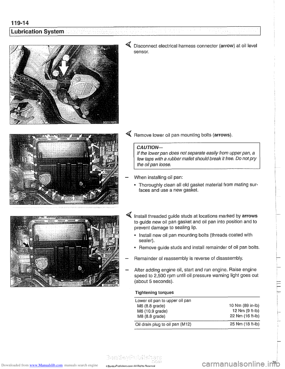
< Disconnect electrical harness connector (arrow) at oil level
sensor.
< Remove lower oil pan mounting bolts (arrows)
CAUTIOI\C
If the lowerpan does not separate easily from upperpan, a
few taps with a rubber mallet should break it free. Do
notpry
the oil pan loose.
- When installing oil pan:
Thoroughly clean all old
gasltet material from mating sur-
faces and use a new gasket.
4 Install threaded guide studs at locations marked by arrows
to guide new oil pan
gasltet and oil pan into position and to
prevent damage to sealing lip.
- Install new oil pan mounting bolts (threads coated with
sealer).
Remove guide studs and install remainder of oil pan bolts.
- Remainder of reassembly is reverse of disassembly
- After adding engine oil, start and run engine. Raise engine
speed to 2,500 rpm until oil pressure warning light goes out
(about 5 seconds).
Tightening torques Lower oil pan to upper
oil pan
M6 (8.8 grade) 10 Nm (89 in-lb)
M6 (10.9 grade) 12 Nm (9 ft-lb)
M8 (8.8 grade) 22 Nm (16 ft-lb)
Oil drain plug to oil pan (M12) 25 Nm (18 ft-lb)
Page 340 of 1002
Downloaded from www.Manualslib.com manuals search engine
Lubr~cat~on System r- -
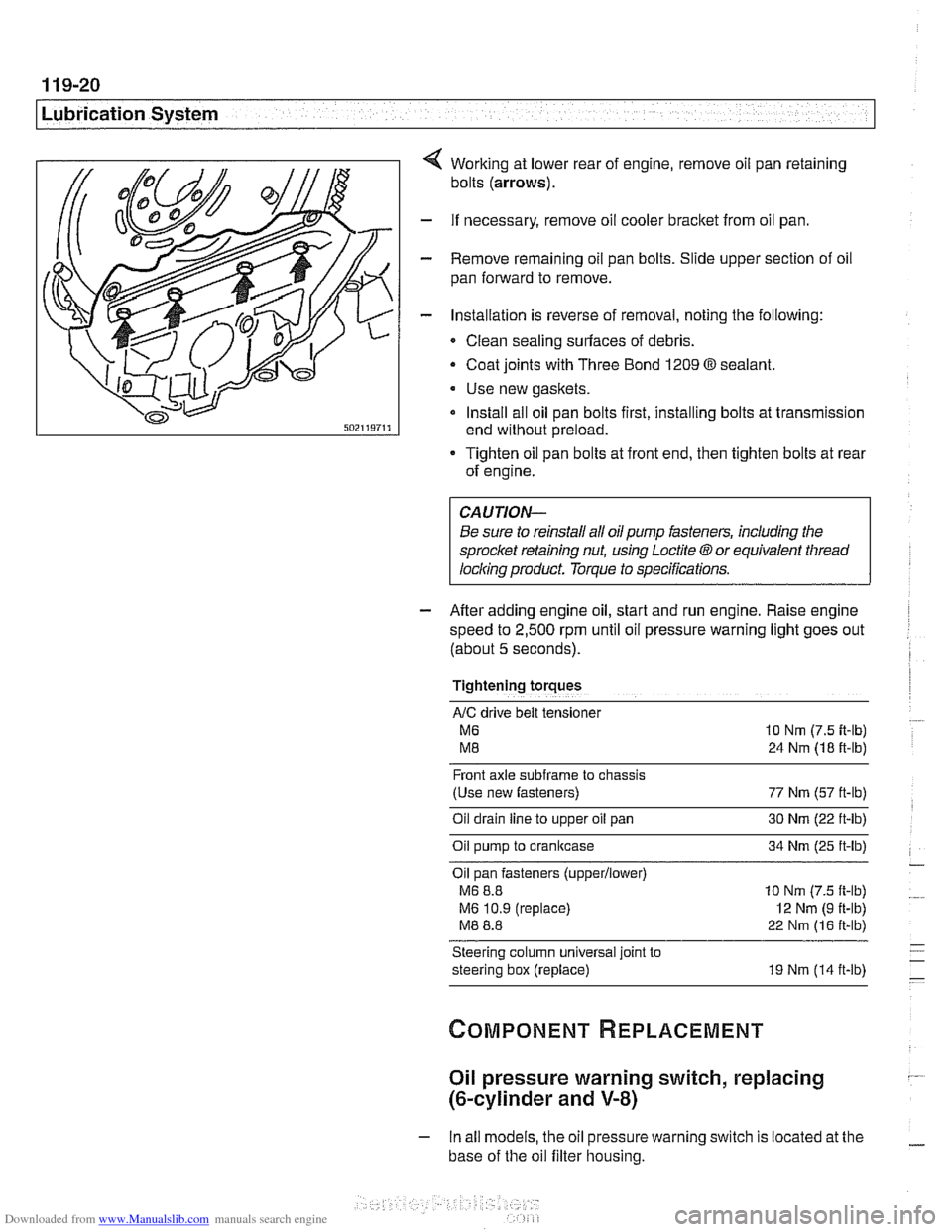
Working at lower rear of engine, remove oil pan retaining
bolts
(arrows).
- If necessary, remove oil cooler bracket from oil pan.
- Remove remaining oil pan bolts. Slide upper section of oil
pan forward to remove.
- Installation is reverse of removal, noting the following:
Clean sealing surfaces of debris.
- Coat joints with Three Bond 1209 O sealant.
Use new gaskets.
Install all oil pan bolts first, installing bolts at transmission
end without preload.
Tighten oil pan bolts at front end, then tighten bolts at rear
of engine.
Be sure to reinstall all oil
pump fasteners, including the
sprocl
speed to
2,500 rpm until oil pressure warning light goes out
(about
5 seconds).
Tightening torques
AIC drive belt tensloner
M6 10 Nm (7.5 it-lb)
M8 24 Nm (18 ft-lb)
Front axle
subframe to chassis
(Use new fasteners) 77 Nm (57 ft-lb)
Oil drain
line to upper oil pan 30 Nm (22 ft-lb)
Oil pump to crankcase 34 Nm (25 ft-lb)
Oil pan fasteners
(upperllower)
M6 8.8 10 Nm (7.5 ft-lb)
M6 10.9 (replace)
I2 Nm (9 ft-lb)
M8 8.8 22 Nm (16 ft-lb)
Steering column universal joint to
steering box (replace) 19 Nm (14 ft-lb)
Oil pressure warning switch, replacing
(&cylinder and V-8)
- In all models, the oil pressure warning switch is located at the
base of the oil filter housing.
Page 343 of 1002
Downloaded from www.Manualslib.com manuals search engine
Lubrication System
- Lower front suspension and remove oil pan, as described
earlier, to gain access to oil pump.
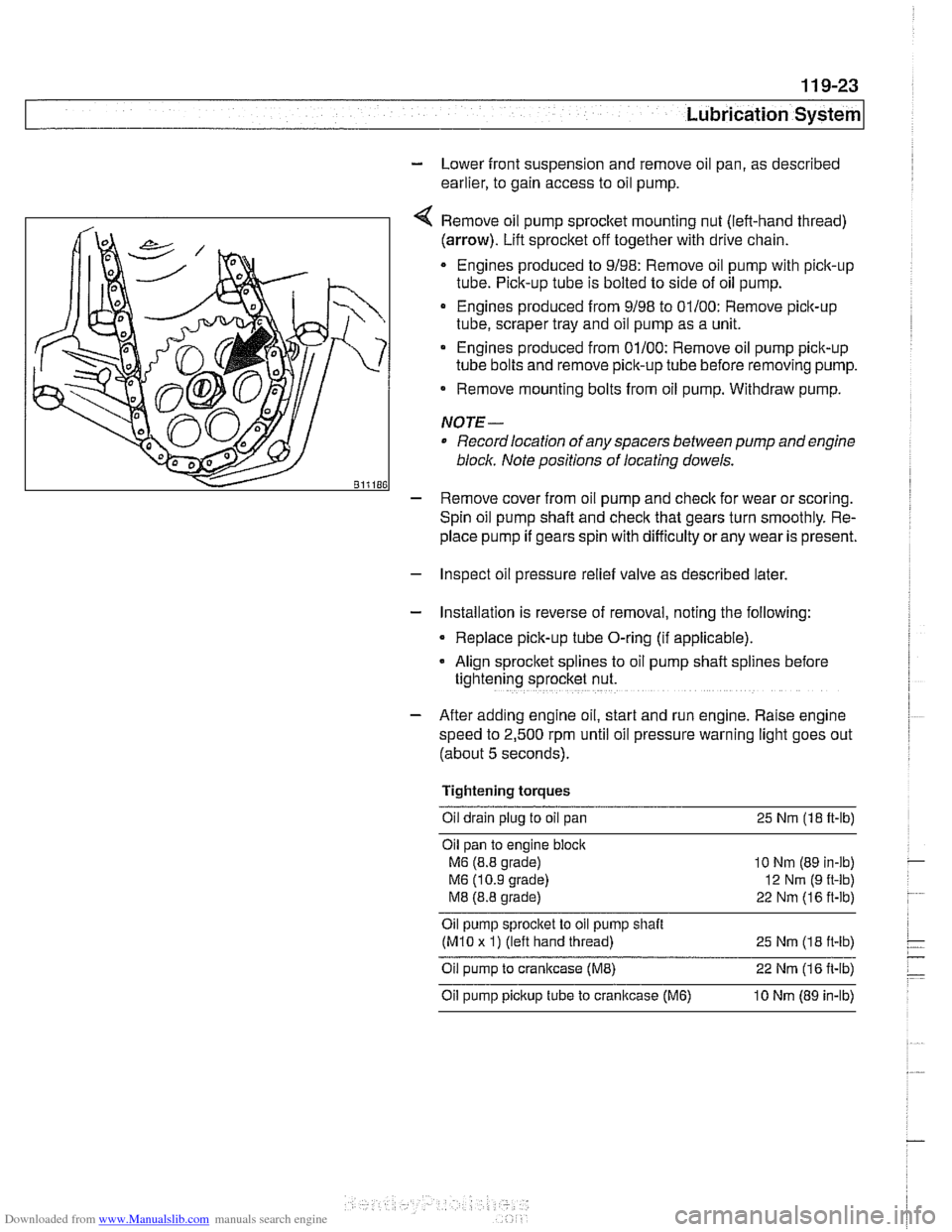
Remove oil pump
sprocket mounting nut (left-hand thread)
(arrow). Lift sprocket off together with drive chain.
Engines produced to 9/98: Remove oil pump with pick-up
tube. Pick-up tube is bolted to side of oil pump.
Engines produced from 9/98 to 01/00: Remove pick-up
tube, scraper tray and oil pump as a unit.
Engines produced from 01/00: Remove oil pump pick-up
tube bolts and remove pick-up tube before removing pump.
Remove mounting bolts from oil pump. Withdraw pump.
NOTE-
Record location of any spacers between pump and engine
bloclc Note positions of locating dowels.
- Remove cover from oil pump and check for wear or scoring.
Spin oil pump shaft and
check that gears turn smoothly. Re-
place pump if gears spin with difficulty
orany wear is present.
- Inspect oil pressure relief valve as described later.
- Installation is reverse of removal, noting the following:
Replace pick-up tube O-ring (if applicable).
- Align sprocket splines to oil pump shaft spl~nes before
tightening sprocket nut.
- After adding engine oil, start and run engine. Raise engine
speed to 2,500 rpm until oil pressure warning light goes out
(about 5 seconds).
Tightening torques Oil drain plug to oil pan 25
Nm (18 ft-lb)
Oil pan to engine
bloclc
M6 (8.8 grade)
M6 (10.9 grade)
M8 (8.8 grade)
10 Nm (89 in-lb)
12
Nrn (9 ft-lb)
22 Nm (16 ft-lb)
Oil pump sprocket to oil pump shait
(M10 x 1) (left hand thread)
25 Nm (1 8 it-lb)
Oil pump to crankcase (ME) 22 Nm (1 6 it-lb)
Oil pump pickup tube to cranltcase (M6) 10 Nm (89 in-lb)
Page 346 of 1002
Downloaded from www.Manualslib.com manuals search engine
11 9-26
/Lubrication System
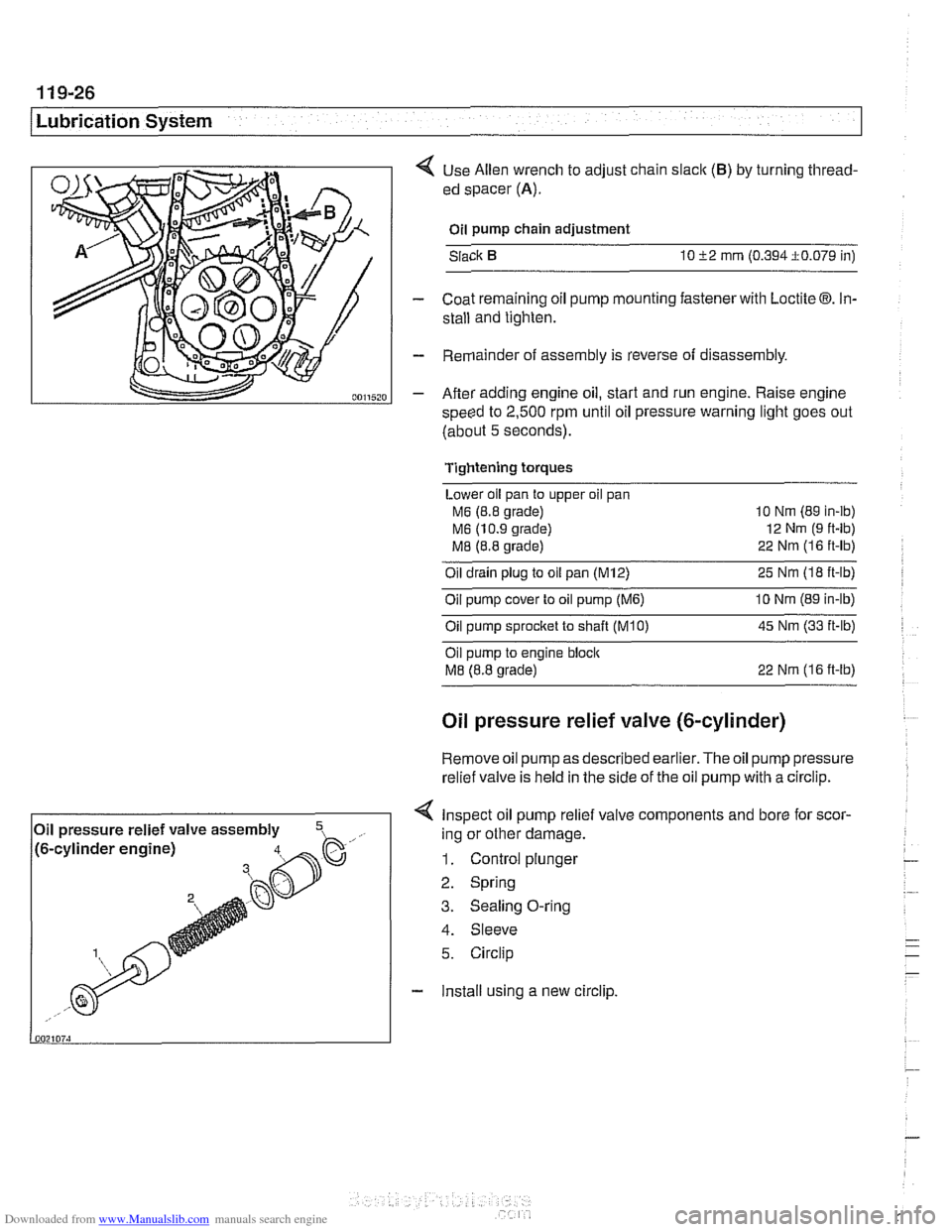
< Use Allen wrench to adjust chain slaclc (B) by turning thread-
ed spacer
(A).
Oil pump chain adjustment
Slack
10 52 mrn (0.394i0.079 in)
- Coat remaining oil pump mounting fastener with Loctite 03. In-
stall and tighten.
- Remainder of assembly is reverse of disassembly.
- After adding engine oil, start and run engine. Raise engine
speed to
2,500 rpm until oil pressure warning light goes out
(about
5 seconds).
Tightening torques
Lower oil pan to upper oil pan
M6 (8.8 grade) 10
Nm (89 in-ib)
M6 (10.9 grade) 12
Nm (9 ft-lb)
M8 (8.8 grade) 22
Nrn (1 6 ft-lb)
Oil drain plug to oil pan (M12) 25 Nm (I8 ft-lb)
Oil pump cover to oil pump
(M6) 10 Nrn (89 in-lb)
Oilpump sprocket to shaft TKO) 45 Nm (33 it-lb)
Oil pump to engine bloclc
M8 (8.8 grade) 22 Nrn (16 ft-lb)
Oil pressure relief valve (&cylinder)
Remove oil
pump as described earlier. The oil pump pressure
relief valve is held in the side of the
oil pump with a circlip.
< Inspect oil pump relief valve components and bore for scor-
4. Sleeve
5. Circlip
- Install using a new circlip.
Oil
pressure relief valve assembly
,- ..., !~. -.-~. - ~- -~!~~-% h. .- .,, /to-cy~~noer engrnej ing or other damage.
1. Control plunger
2. Spring
3. Sealing O-ring
Page 350 of 1002
Downloaded from www.Manualslib.com manuals search engine
Ignition System
This repair group covers component troubleshooting and re-
placement information for the ignition system.
When diagnosing engine management problems, including
on-board diagnostics (OBD
11) fault code analysis, also refer
to these repair groups:
* 130 Fuel Injection
* ELE Electrical Wiring Diagrams
OED On-Board Diagnostics
Special tools
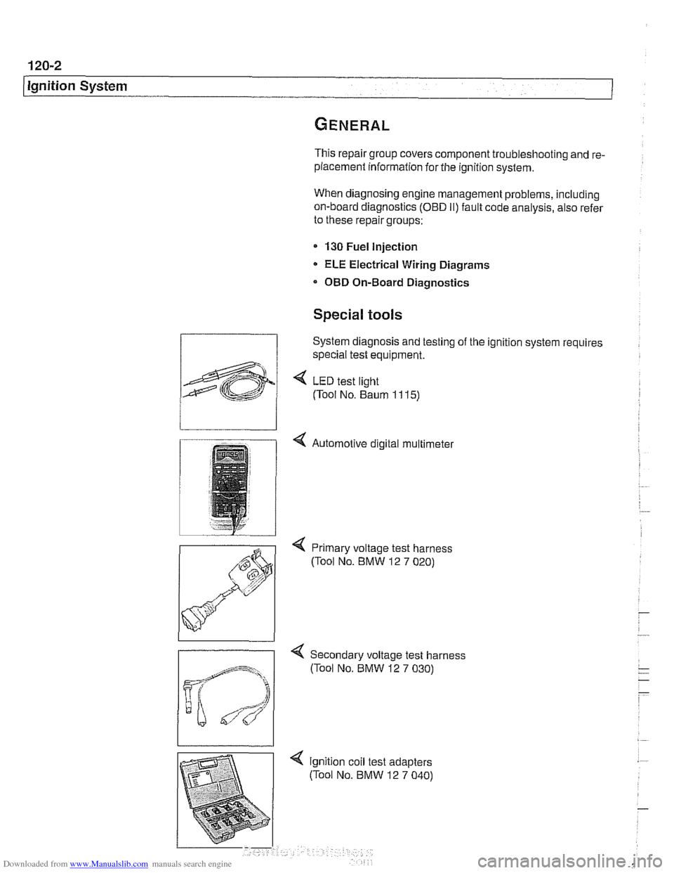
System diagnosis and testing of the ignition system requires
special test equipment.
4 LED test light
(Tool No. Baum
1 1 15)
4 Automotive digital multimeter
4 Primary voltage test harness
(Tool No. BMW 12
7 020)
-
4 Secondary voltage test harness
(Tool No. BMW 12
7 030)