ECO BMW 525i 1997 E39 Manual PDF
[x] Cancel search | Manufacturer: BMW, Model Year: 1997, Model line: 525i, Model: BMW 525i 1997 E39Pages: 1002
Page 205 of 1002
Downloaded from www.Manualslib.com manuals search engine
--
Cylinder Head and valvetrain1
Double VANOS secondary timing chain components,
installing
(M52 TU, M54 engine)
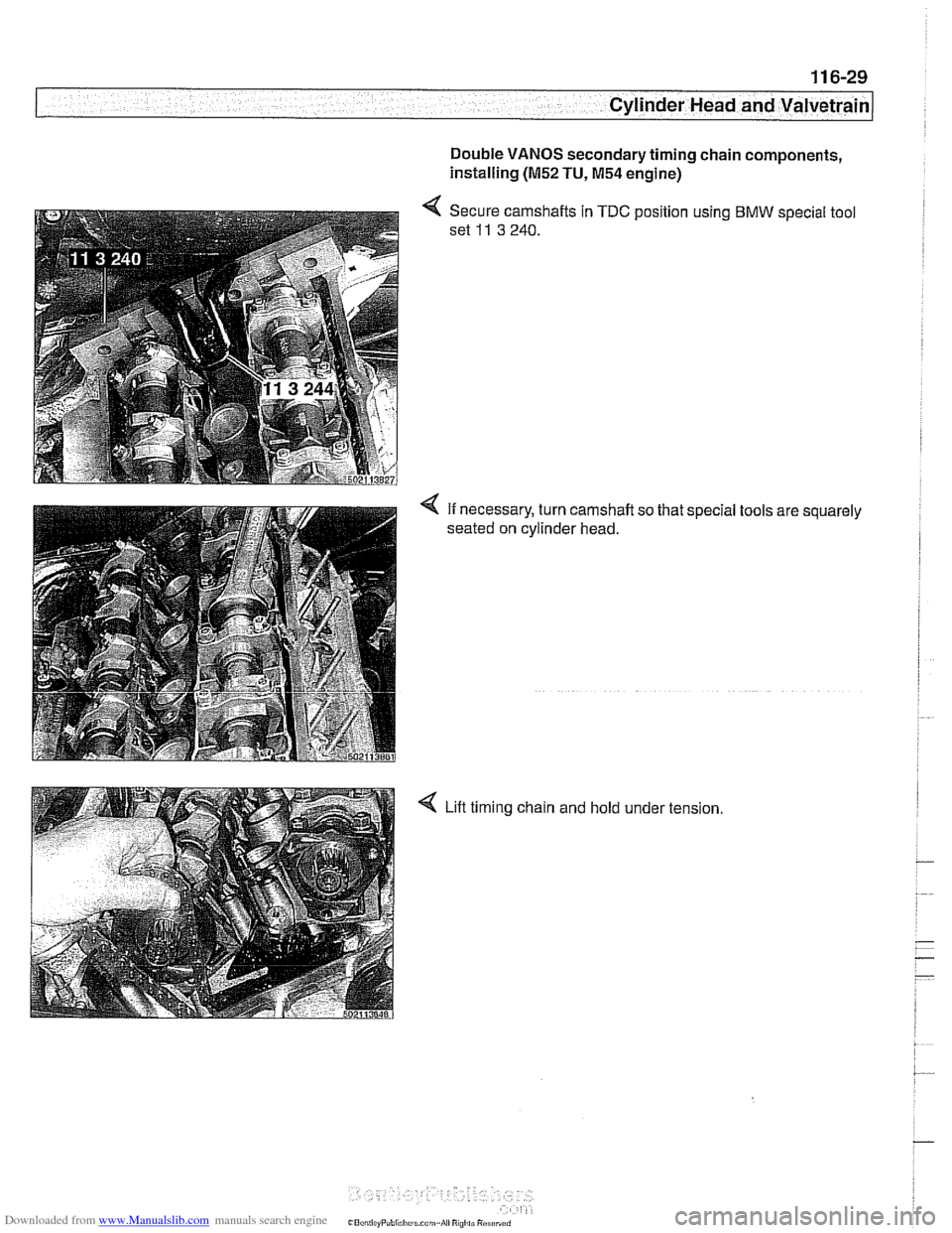
< Secure camshafts in TDC position using BMW special tool
set
11 3 240.
4 If necessary, turn camshaft so that special tools are squarely
seated on cylinder head.
4 Lift timing chain and hold under tension
Page 208 of 1002
Downloaded from www.Manualslib.com manuals search engine
11 6-32
Cylinder Head and Valvetrain
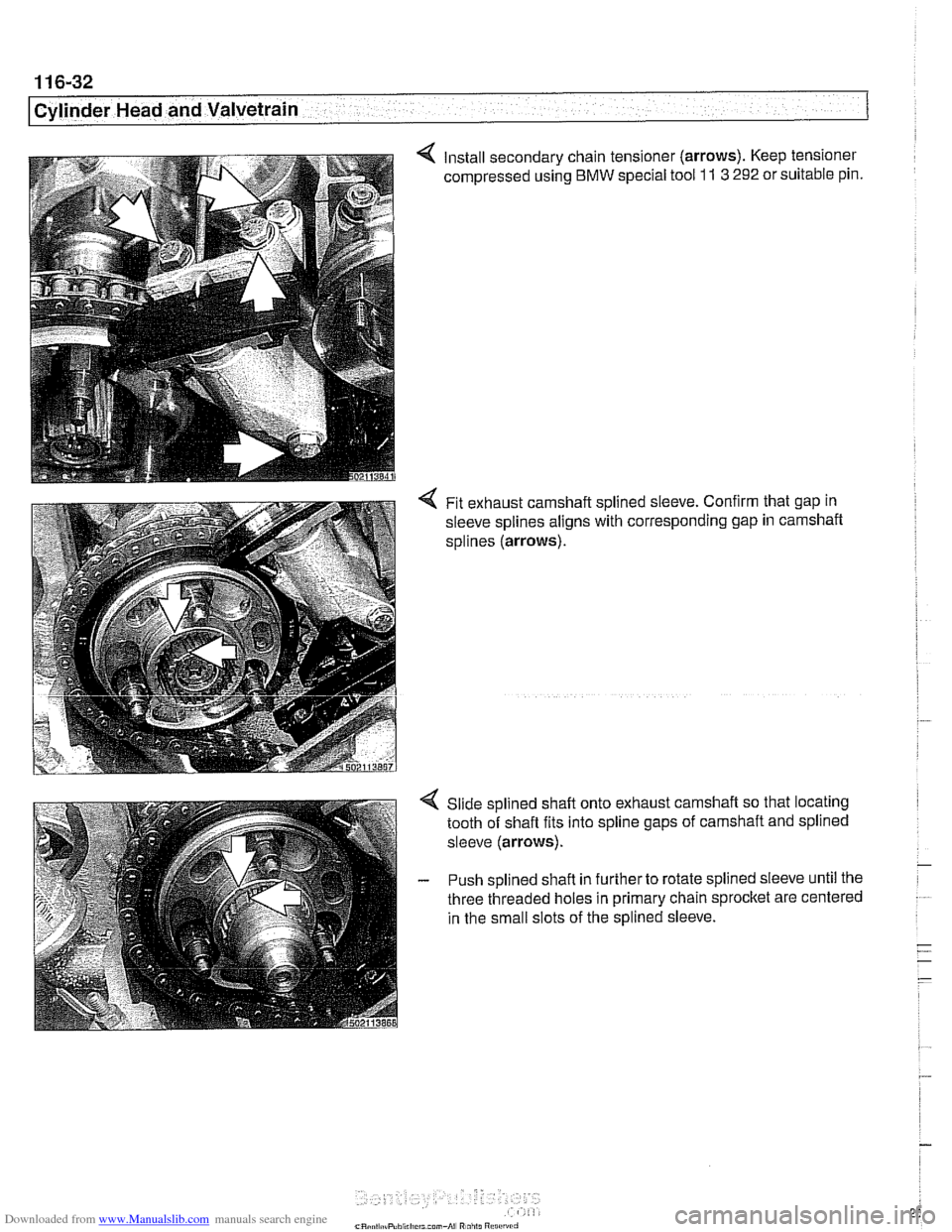
4 Install secondary chain tensioner (arrows). Keep tensioner
compressed using
BMW special tool 11 3 292 or suitable pin.
4 Fit exhaust camshaft splined sleeve. Confirm that gap in
sleeve splines aligns with corresponding gap in carnshaft
splines
(arrows).
Slide splined shaft onto exhaust camshaft so that locating
tooth of shaft fits into spline gaps of camshaft and splined
sleeve
(arrows).
- Push splined shafl in further to rotate splined sleeve until the
three threaded holes in primary chain sprocket are centered
in the small slots of the splined sleeve.
Page 209 of 1002
Downloaded from www.Manualslib.com manuals search engine
Cylinder Head and valvetrain1
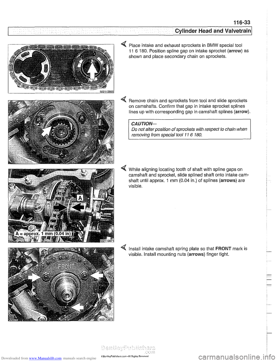
< Place intake and exhaust sprockets in BMW special tool
11 6 180. Position spline gap on intake sprocket (arrow) as
shown and place secondary chain on
sprocitets.
< Remove chain and sprockets from tool and slide sprockets
on camshafts. Confirm that gap in intalte sprocket splines
lines up with corresponding gap in camshaft splines (arrow).
CAUTIOI\C
Do not alter position of sprockets with respect to chain when
removinq from saecial tool 11 6 180.
4 While aligning locating tooth of shaft with spline gaps on
camshaft and sprocket, slide spiined
shaft onto intalte carn-
shaft until approx. 1 mm (0.04 in.) of splines (arrows) are
visible.
4 lnstall intake camshaft spring plate so that FRONT mark is
visible. install mounting nuts (arrows) finger tight.
Page 211 of 1002
Downloaded from www.Manualslib.com manuals search engine
. .
Cylinder Head and Valvetrain
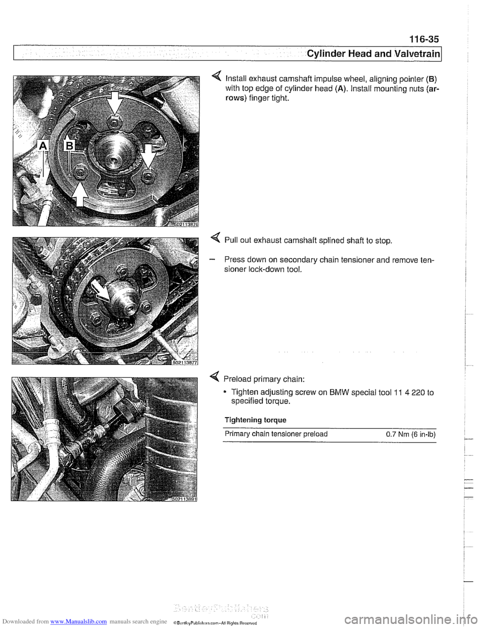
Install exhaust camshaft impulse wheel, aligning pointer (B)
with top edge of cylinder head (A). Install mounting nuts (ar-
rows) finger tight.
4 Pull out exhaust camshaft splined shaft to stop.
- Press down on secondary chain tensioner and remove ten-
sioner lock-down tool.
Preload primary chain:
- Tighten adjusting screw on BMW special tool 11 4 220 to
specified torque.
Tightening torque Primary chain tensioner preload
0.7 Nm (6 in-lb)
Page 213 of 1002
![BMW 525i 1997 E39 Manual PDF Downloaded from www.Manualslib.com manuals search engine
-
. - - -- Cylinder Head and valvetrain]
Turn engine over twice in direction of rotation until cylinder 1
intake and exhaust camshaft](/img/1/2822/w960_2822-212.png "BMW 525i 1997 E39 Manual PDF Downloaded from www.Manualslib.com manuals search engine
-
. - - -- Cylinder Head and valvetrain]
Turn engine over twice in direction of rotation until cylinder 1
intake and exhaust camshaft")
Downloaded from www.Manualslib.com manuals search engine
-
. - - -- Cylinder Head and valvetrain]
Turn engine over twice in direction of rotation until cylinder 1
intake and exhaust camshaft lobes (arrows) face each other.
- Lock crankshaft in TDC position with BMW special tool
11 2 300.
4 Place BMW special tool set 11 3 240 over camshafts and
measure clearances.
NOTE-
@ If the exhaust side of the tool (A) is not flush with the head,
camshaft timing is incorrect. Reset camshaft timing as de-
scribed in 11
7 Camshaft Timing Chain.
Due to flexible sprocket design, VANOS unit tolerances
and play in the VANOS splines, when the camshaft timing
is set correctly, the intake side of special tool set
11 3 240
(B) may be up to 1 mm (0.04 in.) above the suiface of the
cylinder head. This is normal. Reassemble engine. Other-
wise, reset camshaft timing as describedin 1
l?Camshaft
Timing Chain.
- Remove BMW special tool 11 6 150 from front of cylinder
head.
4 Clean contact edges of cylinder head face and VANOS unit
and apply a thin coat of Three Bond
12090 or equivalent
sealing compound to surfaces.
CAUTION-
Male sure all gasket material is removed from face of cyl-
inder head. Clean sealing face and keep free of oil.
Check locating dowel
(A) and dowel sleeve (B) at top
of cylinder head for damage or incorrect installation.
- Using a new steel gasket, install VANOS unit to front of cyi-
inder head. See 117 Camshaft Timing Chain.
NOTE-
If VANOS control unit is being replaced, be sure to check and
adjust camshaft timing as described in 117 Camshaft Tim-
ing Chain.
- Reinstall engine lifting eye.
- Reconnect electrical harness connectors to camshaft posi-
tion sensors and
VANOS solenoid valves.
Page 214 of 1002
Downloaded from www.Manualslib.com manuals search engine
I Cylinder Head and Valvetrain
- Remove adjustable primary timing chain tensioner tool and
reinstall primary chain tensioner cylinder to cylinder head.
Tightening torque
Primary chain tensioner cylinder
to 70 Nm (52 ft-lb)
cylinder head
- Remove flywheel locking tool from crankcase. Replace spe-
cial tool bore sealing plug.
- Remove camshaft locking tools from cylinder head
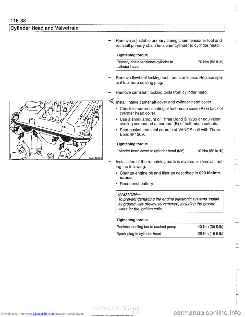
Install intake camshaft cover and cylinder head cover.
Check for correct seating of half-moon seals (A) in back of
cylinder head cover.
Use a small amount of Three Bond
8 1209 or equivalent
sealing compound at corners
(B) of half-moon cutouts.
Seat gasket and seal corners at VANOS unit with Three
Bond
@ 1209.
Tightening torque Cylinder head cover to cylinder head
(M6) 10 Nm (89 in-lb)
- Installation of the remaininq parts is reverse or removal, not- -
ing the following:
Change engine
011 and f~lter as descr~bed in 020 Mainte-
nance.
Reconnect battery.
To prevent damaging the engine electronic systems, install
all ground wire previously removed, including the ground
wires for the ignition coils.
Tightening torque
-
Radiator cooling fan to coolant pump 40 Nm
(30 ft-ib)
Spark plug to cylinder head
25 Nm (18 ft-ib)
Page 218 of 1002
Downloaded from www.Manualslib.com manuals search engine
11 6-42
/ Cvlinder Head and Valvetrain
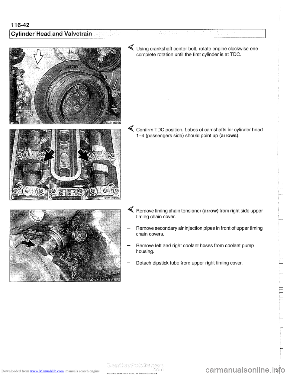
4 Using crankshaft center bolt, rotate engine clockwise one
complete rotation until the first cylinder is at TDC.
4 Confirm TDC position. Lobes of camshafts for cylinder head
1-4 (passengers side) should point up (arrows).
4 Remove timing chain tensioner (arrow) from right side upper
timing chain cover.
- Remove secondary air injection pipes in front of upper timing
chain covers.
- Remove left and right coolant hoses from coolant pump
housing.
- Detach dipsticlc tube from upper right timing cover,
Page 220 of 1002
Downloaded from www.Manualslib.com manuals search engine
..
ICylinder Head and Valvetrain -.I
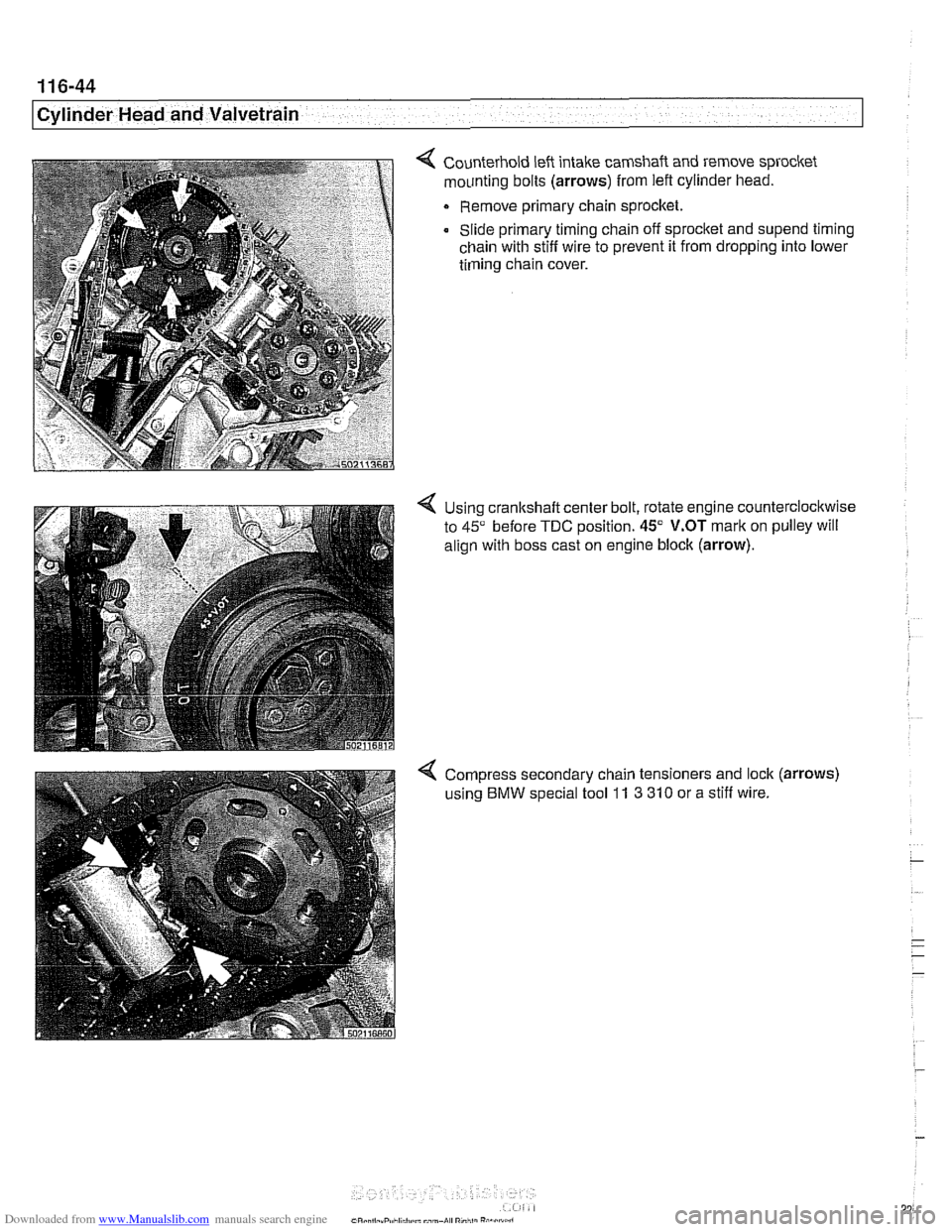
4 Counterhold left intake camshaft and remove sprocket
mounting bolts
(arrows) from left cylinder head.
Remove primary chain sprocket.
Slide primary timing chain off sprocket and
supend timing
chain with stiff wire to prevent it from dropping into lower
timing chain cover.
4 Using cranltshaft center bolt, rotate engine counterclockwise
to
45" before TDC position. 45" V.OT mark on pulley will
align with boss cast on engine block
(arrow).
4 Compress secondary chain tensioners and lock (arrows)
using BMW special tool 11 3 310 or a stiff wire.
Page 226 of 1002
Downloaded from www.Manualslib.com manuals search engine
1 16-50
/Cylinder Head and Valvetrain
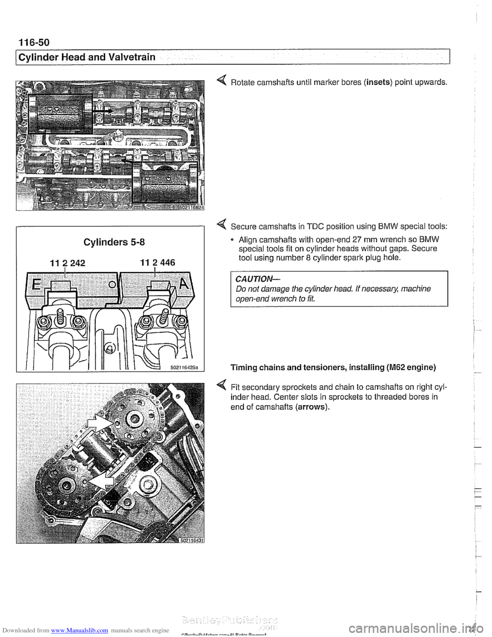
4 Rotate camshafts until marker bores (insets) point upwards,
4 Secure camshafts in TDC position using BMW special tools:
Cylinders 5-8 Align camshafts w~th open-end 27 mm wrench so BMW
special tools fit on cylinder heads without gaps. Secure
11 2 242 11 2 446 I tool using number 8 cylinder spark plug hole.
CAUTION-
Do not damage the cylinder head. If necessary, machine
open-end wrench to
fit.
Timing chains and tensioners, installing (M62 engine)
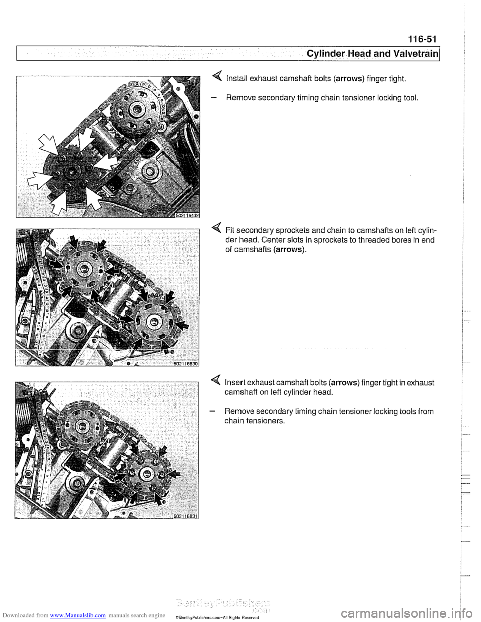
4 Fit secondary sprocltets and chain to camshafts on right cyl-
inder head. Center slots in sprocltets to threaded bores in
end of camshafts (arrows).
. .
Page 227 of 1002
Downloaded from www.Manualslib.com manuals search engine
- -.
Cylinder Head and valvetrain1
Install exhaust camshaft bolts (arrows) finger tight.
Remove secondary timing chain tensioner
loclting tool.
< Fit secondary sprockets and chain to camshafts on left cylin-
der head. Center slots in sprocltets to threaded bores in end
of camshafts
(arrows).
Insert exhaust camshaft bolts (arrows) finger tight in exhaust
camshaft on left cylinder head.
Remove secondary timing chain tensioner locking tools from
chain tensioners.