ECO BMW 525i 1997 E39 Manual Online
[x] Cancel search | Manufacturer: BMW, Model Year: 1997, Model line: 525i, Model: BMW 525i 1997 E39Pages: 1002
Page 232 of 1002
Downloaded from www.Manualslib.com manuals search engine
1 16-56
Cylinder Head and Valvetrain
This section covers valve removal and reconditioning, includ-
ing valve guides, seats, springs, and valve stem oil seals.
Valves, leak test
To test the valves for leakage, the cylinder head must be dis-
assembled with camshafts and camshaft carriers removed.
With valve assemblies and spark plugs installed, place the
cylinder head on a workbench with the combustion chamber
facing upward. Fill each combustion chamber with a thin non-
flammable liquid. After fifteen minutes,
check the level of the
fluid. If the fluid level in any cylinder drops, that cylinder is not
sealing properly.
Valves, removing and installing
- Remove cylinder head as described in 113 Cylinder Head
Removal and Installation.
CAUTIOI\C
(M52 TU/M54 engines only) Do not let the hydraulic lifters
fall out as the camshaft carrier is removed. Special suction
cups are available from
BMW to hold the hydraulic lifters in
place during carrier removal.
* Hydraulic cam lifters should be stored m an uprfght po-
sition. If necessary, use a magnetic tool to
aidin remov-
al of the lifters.
- Remove valves using a valve spring compressor.
CAUTIOI\C
Label each valve assembly as it is removed so it can be in-
stalled in its original position.
-
- Remove and discard valve stem oil seals from valve guides.
See Valve stem oil seals later in this section.
- Valve installation is reverse of removal. Remove carbon de- - -
posits from the valves using a wire brush or wire wheel. -
-
Valve specifications are listed in Table c. Valve specifica-
tions.
Page 235 of 1002
Downloaded from www.Manualslib.com manuals search engine
Cylinder Head and valvetrain1
Valve seats
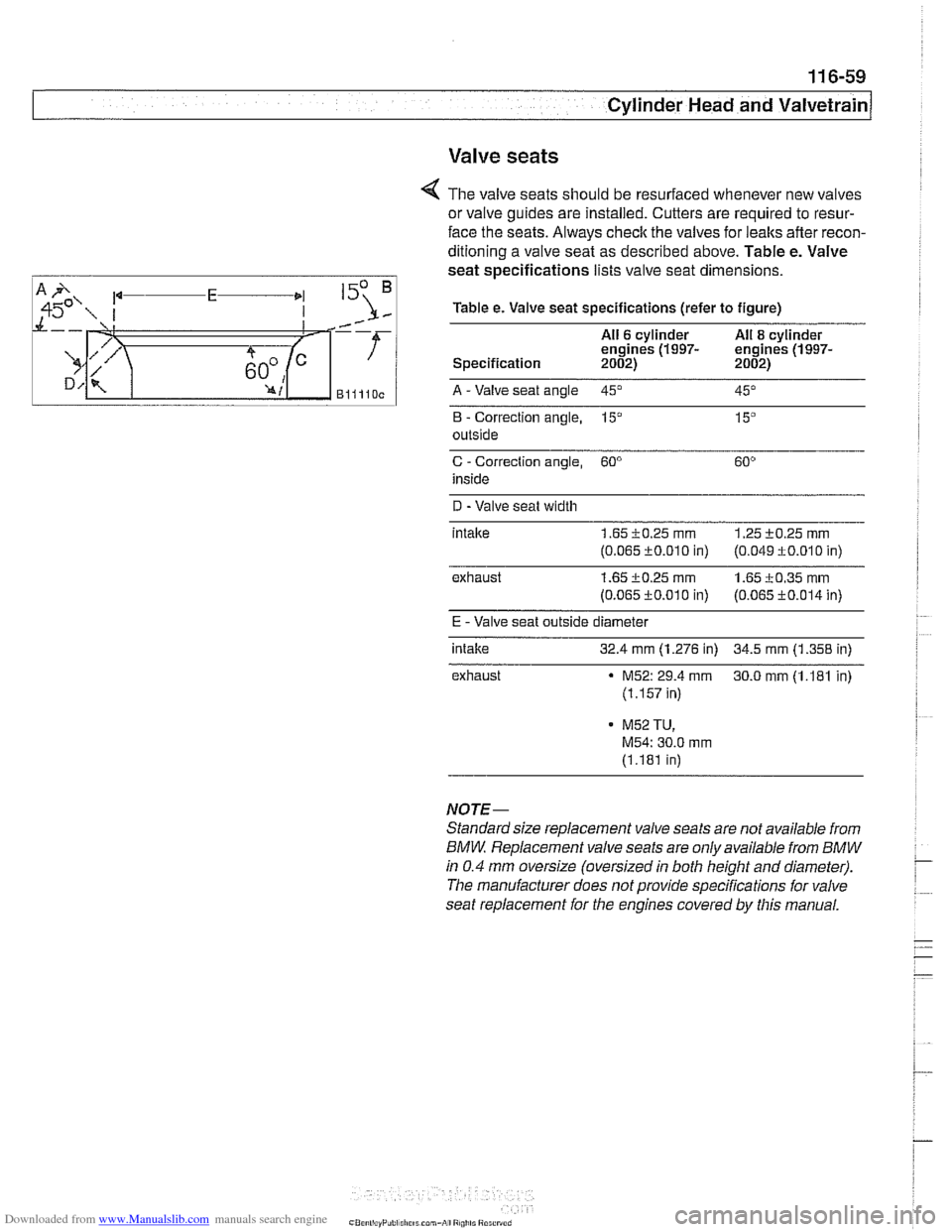
< The valve seats should be resurfaced whenever new valves
or valve guides are installed. Cutters are required to resur-
face the seats. Always check the valves for leaks after recon-
ditioning a valve seat as described above. Table e. Valve
seat specifications lists valve seat dimensions.
Table e. Valve seat specifications (refer to figure)
All
6 cylinder All 8 cylinder
engines (1997- engines (1997- Specification 2002) 2002)
Blllloc A -Valve seat angle 45" --. -- 45"
B - Correction angle, 15" 15"
outside
C - Correction angle, 60"
inside
D -Valve seat width
intalte
1.65 i0.25 rnrn 1.25 +0.25 rnm
(0.065 c0.010 in) (0.049 f 0.010 in)
exhaust
1.65 c0.25 rnm 1.65 i0.35 rnm
(0.065 fO.O1O in) (0.065 c0.014 in)
E - Valve seat outside diameter
intake
32.4 mm (1.276 in) 34.5 mm (1.358 in)
exhaust
M52: 29.4 rnm 30.0 rnm (1.181 in)
(1.157 in)
- M52 TU,
M54: 30.0 mrn
(1.181 in)
NOTE-
Standard size replacement valve seats are not available from
BMW Replacement valve seats are only available from BMW
in 0.4 mm oversize (oversized in both height and diameter).
The manufacturer does not provide specifications for valve
seat replacement for the engines covered by this manual.
Page 240 of 1002
Downloaded from www.Manualslib.com manuals search engine
[Camshaft Timing Chain
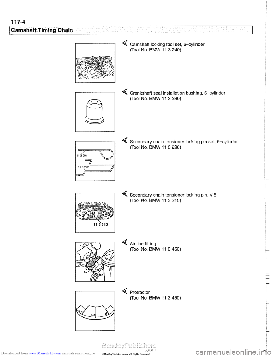
4 Camshaft locking tool set, 6-cylinder
(Tool No. BMW
11 3 240)
- 4 Crankshaft seal installation bushing. 6-cylinde~
4 Secondary chain tensioner locking pin set. 6-cylinder
(Tool No.
BMW 11 3 290)
11 3292
4 Secondary chain tensioner loclting pin, V-8
(Tool No. BMW 11 3 310)
4 Air line fitting
(Tool No. BMW
11 3 450)
4 Protractor
(Tool No. BMW
11 3 460)
Page 250 of 1002
Downloaded from www.Manualslib.com manuals search engine
I Camshaft Timing Chain
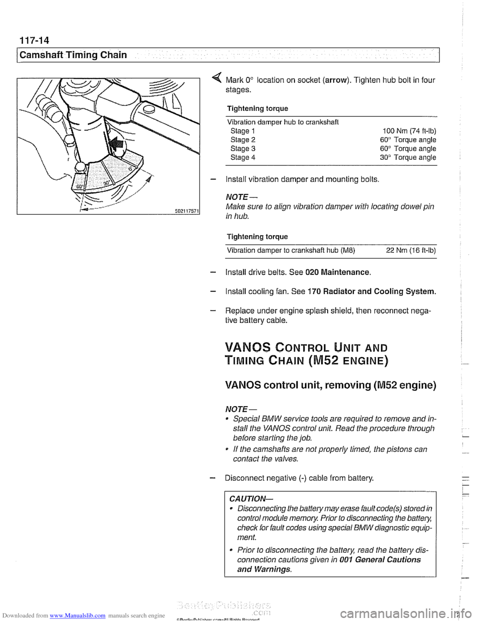
Mark 0" location on socket (arrow). Tighten hub bolt in four
stages.
Tightening torque Vibration damper
hub to cranlrshaft
Stage 1 100 Nm (74 it-lb)
Stage
2 60" Torque angle
Stage
3 60" Torque angle
Stage
4 30" Torque angle
- install vibration damper and mounting bolts
NOTE-
Male sure to align vibration damper with locating dowel pin
in hub.
Tightening torque Vibration damper to
cranltshait hub (ME) 22 Nm (16 ft-lb)
- Install drive belts. See 020 Maintenance.
- Install cooling fan. See 170 Radiator and Cooling System.
- Replace under engine splash shield, then reconnect nega-
tive battery cable.
!/ANBS CONTROL UNIT AND
TIMING CHAIN (M52 ENGINE)
VANOS control unit, removing (M52 engine)
NOTE-
Special BMW service tools are required to remove and in-
stall the
VANOS control unit. Read the procedure through
before starting the job.
If the camshafts are notproperly timed, the pistons can
contact the valves.
- Disconnect negative (-) cable from battery.
CAUTION-
Disconnecting the battery may erase fault code(s) stored in
control module memory. Prior to disconnecting the
battev,
check for fault codes using special BMW diagnostic equip-
ment.
* Prior to disconnecting the battery, read the battery dis-
connection cautions given in
001 General Cautions
and Warnings.
Page 254 of 1002
Downloaded from www.Manualslib.com manuals search engine
117-18
Camshaft Timing Chain
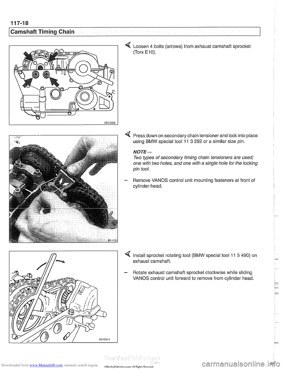
4 Loosen 4 bolts (arrows) from exhaust camshait sprocket
(Torx E10).
Press down on secondary chain tensioner and lock into place
using BMW special tool
11 3 292 or a similar size pin.
NOTE-
Two types of secondary timing chain tensioners are used;
one with two holes, and one with a single hole for the
locl
Remove VANOS control unit mounting fasteners at front of
cylinder head.
4 Install sprocltet rotating tool (BMW special tool 11 5 490) on
exhaust camshaft.
- Rotate exhaust camshaft sprocket clockwise while sliding
VANOS control unit forward to remove from cylinder head.
Page 256 of 1002
Downloaded from www.Manualslib.com manuals search engine
11 7-20
Camshaft Timing Chain
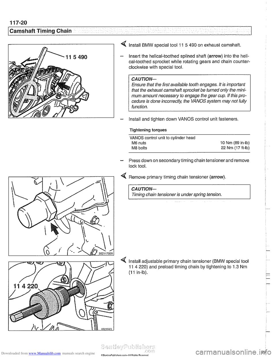
4 lnstall BMW special tool 1 I 5 490 on exhaust camshaft.
- Insert the helical-toothed splined shafl (arrow) into the heli-
cal-toothed sprocket while rotating gears and chain counter-
clockwise with special tool.
CAUTION- Ensure
that the first available tooth engages. It is important
that the exhaust camshaft sprocket be turned only the mini-
mum amount necessary to engage the gear cup. If this pro-
cedure is done
incorrectlq: the VANOS system may not fully
function.
- Install and tighten down VANOS control unit fasteners
Tightening torques
VANOS control unit to cylinder head
M6 nuts 10 Nm (89 in-lb)
M8 bolts 22 Nrn (17 ft-lbj
- Press down on secondary timing chain tensioner and remove
lock tool.
Remove primary timing chain tensioner
(arrow)
CAUTION-
Timing chain tensioner is under spring tension.
lnstall adjustable primary chain tensioner
(BMW special tool
11 4 220) and preload timing chain by tightening to 1.3 Nm
(I I in-lb).
Page 257 of 1002
Downloaded from www.Manualslib.com manuals search engine
Camshaft Timing Chain/ - - - - - - . - - . - .
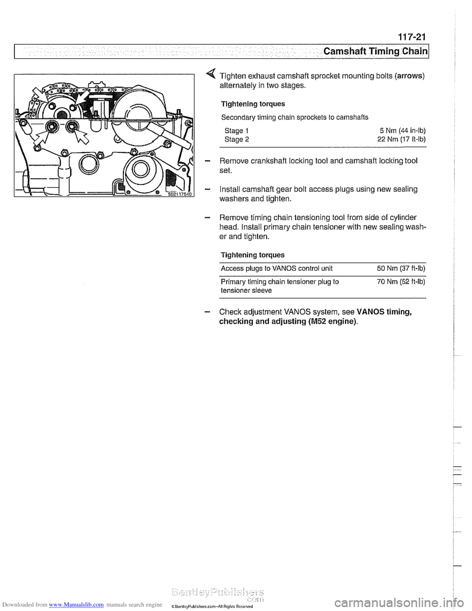
Tighten exhaust camshaft sprocket mounting bolts (arrows)
alternately in two stages.
Tightening torques
Secondary timing chain sprocltets to camshafts
Stage
1
Stage 2
5 Nm (44 in-lb)
22 Nm (17 ft-lb)
- Remove crankshaft locking tool and camshaft locking tool
set.
- install camshaft gear bolt access plugs using new sealing
washers and tighten.
- Remove timing chain tensioning tool from side of cylinder
head. Install primary chain tensioner with new sealing wash-
er and tighten.
Tightening torques
Access plugs to VANOS control unit 50 Nm (37 ft-lb)
Primary timing chain tensioner
plug to 70 Nm (52 ft-lb)
tensioner sleeve
- Check adjustment VANOS system, see VANOS timing,
checking and adjusting
(M52 engine).
Page 260 of 1002
Downloaded from www.Manualslib.com manuals search engine
1 17-24
I Camshaft Timing Chain
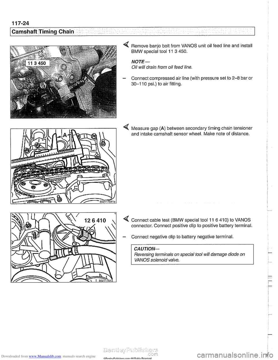
4 Remove banjo bolt from VANOS unit oil feed line and install
BMW special tool 11 3 450.
NOTE-
Oil will drain from oil feed line.
- Connect compressed air line (with pressure set to 2-8 bar or
30-1 10 psi.) to air fitting.
4 Measure gap (A) between secondary timing chain tensioner
and
intake camshaft sensor wheel. Make note of distance.
4 Connect cable test (BMW special tool 11 6 410) to VANOS
connector. Connect positive clip to positive battery terminal.
- Connect negative clip to battery negative terminal.
CAUTION-
Reversing terminals on special tool will damage diode on
VANOS solenoid valve.
Page 261 of 1002
Downloaded from www.Manualslib.com manuals search engine
-
Camshaft Timing Chain -. -
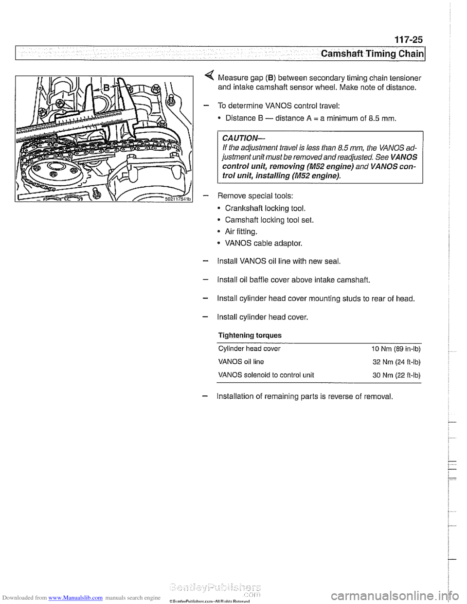
Measure gap (B) between secondary timing chain tensioner
and intake camshaft sensor wheel. Make note of distance.
To determine VANOS control travel:
Distance
I3 - distance A = a minimum of 8.5 mm
CAUTION-
If the adjustment travel is less than 8.5 mm the VANOS ad-
justment unit must be removed and readjusted. See
VANOS
control unit, removing (M52 engine)
and VANOS con-
trol unit, installing
(M52 engine).
Remove special tools:
Cranltshaft locking tool.
Camshaft
loclting tool set.
Air fitting.
* VANOS cable adaptor.
- Install VANOS oil line with new seal
- Install oil baffle cover above intake camshaft.
- Install cylinder head cover mounting studs to rear of head.
- Install cylinder head cover,
Tightening
torques
Cylinder head cover 10 Nrn (89 in-lb)
VANOS oil line
32 Nm (24 R-lb)
VANOS solenoid to control unit 30 Nrn (22 ft-lb)
- Installation of remaining parts is reverse of removal.
Page 264 of 1002
Downloaded from www.Manualslib.com manuals search engine
[camshaft Timing Chain
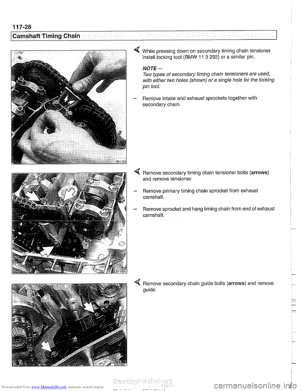
< While pressing down on secondary timing chain tensioner
install locking tool (BMW
11 3 292) or a similar pin.
NOTE-
Two types of secondary timing chain tensioners are used,
with either two holes (shown) or a single hole for the
locking
pin tool.
- Remove intake and exhaust sprockets together with
secondary chain.
< Remove secondary timing chain tensioner bolts (arrows)
and remove tensioner.
- Remove primary timing chain sprocket from exhaust
camshaft.
- Remove sprocket and hang timing chain from end of exhaust
camshaft.
4 Remove secondary chain guide bolts (arrows) and remove
guide.