Wir BMW 540i 1997 E39 Workshop Manual
[x] Cancel search | Manufacturer: BMW, Model Year: 1997, Model line: 540i, Model: BMW 540i 1997 E39Pages: 1002
Page 615 of 1002
Downloaded from www.Manualslib.com manuals search engine
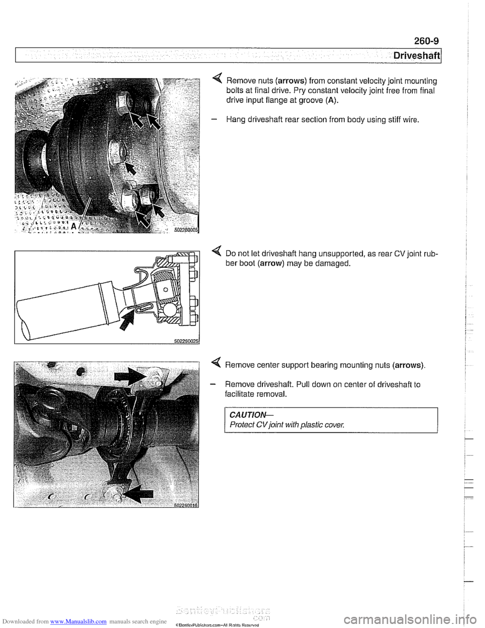
4 Remove nuts (arrows) from constant velocity joint mounting
bolts at final drive. Pry constant velocity joint free from final
drive input flange at groove
(A).
- Hang driveshaft rear section from body using stiff wire.
< Do not let driveshaft hang unsupported, as rear CV joint rub-
ber boot (arrow) may be damaged.
4 Remove center support bearing mounting nuts (arrows)
- Remove driveshaft. Pull down on center of driveshaft to
facilitate removal.
CAUTIOI\C
Protect CVjoint with plastic cover.
Page 616 of 1002
Downloaded from www.Manualslib.com manuals search engine
260-1 0
/ Driveshaft
Driveshaft, installing
- Prepare CV joint for reinstallation:
Extend joint to limit.
Clean off old grease and fill with fresh grease
Install new seal.
- Bend driveshaft slightly at center universal joint to install
CAUTION-
Do not allow CVjoint seal to become displaced.
- Align matchmarlts on driveshaft to matchmarks on final drive
and transmission flanges.
- Fit constant velocity joint to final drive input flange. Alternate-
ly tighten two opposite nuts to draw constant velocity joint
evenly into the final drive input flange. Once seated, tighten
down remaining nuts.
I CAUTION-
I Do not reuse self-locking nuts. These nuts are designed to be /
I used onlv once. 1
- Insert bolts in front of driveshafl to transmission output
flange. Counterhold each bolt while tightening nut.
CAUTION-
. Do not reuse self-locking nuts. These nuts are designed to
be used only once.
Avoid stressing the flex-disc when torquing the bolts.
Do this by counterholding the bolts and turning the nuts
on the flange side.
- Position center support bearing and install mounting nuts.
Use new self-locking nuts.
- Install heat shields.
- Install rear transmission support crossmember.
- Install exhaust system. See 180 Exhaust System.
Reconnect oxygen sensor wiring harnesses and reattach
wiring harness retainers to rear transmission support
crossrnernber.
Page 622 of 1002
Downloaded from www.Manualslib.com manuals search engine
[~us~ension, Steering and Brakes - General
This section of the manual covers front and rear suspension,
braking and steering systems, and contains wheel, tire and
wheel alignment information and specifications. Also covered
here are the integrated braking and suspension systems in-
cluding
antilock braking (ABS), traction control (ASCIDSC),
and electronic height control (EHC).
Vehicle ride height information is at the end of this repair
group. Alignment information is in
320 Steering and Wheel
Alignment.
Aluminum suspension components
In order to reduce vehicle weight, aluminum suspension com-
ponents are used in some models. A test with a magnet will
easily reveal the metal used. If working with aluminum com-
ponents, be sure to read and follow the cautions below.
CAUTION-
* Due to the chemical and corrosion characteristics of alumi-
num, do not bring into contact with battery acid.
Do not use wire brushes with brass or iron bristles.
Only use brushes with stainless steel bristles.
Do not expose to flying sparks from
grinding/cutting op-
erations.
Do not subject to steel welding splashes.
Do not expose to temperatures over
80°C (176"F),
even for short periods. Temperatures in painting facili-
ties are not a problem.
The E39 front suspension subframe is used as a rigid mount-
ing platform for the front suspension arms, stabilizer bar and
steering gear.
The suspension arms, known as the lower control arms and
the tension struts (thrust arms), are connected to the
sub-
frame through rubber bushings. The arms are connected to
the steering
knucltles in a double pivot configuration.
Each front strut assembly includes a tubular strut and a coil
spring. The upper strut mount includes a bearing. The lower
end of each strut housing is fitted to the steering knuckle. The
integral wheel bearing and hub are bolted to the steering
Iknucltle.
6-cylinder and V-8 models use different steering systems and
other front suspension components.
Page 638 of 1002
Downloaded from www.Manualslib.com manuals search engine
31 0-2
I Front Suspension
This repair group covers the repair and replacement of com-
ponents that make up the front suspension of E39 cars.
Two different types of steering systems are used in the E39
series. 6-cylinder
(5251,5281 and 530i) models are equipped
with a rack and pinion type steering system mounted to an
aluminum subframe.
V-8 (540i) models use a steering gear-
box type system mounted to a steel subframe.
See
300 Suspension, Steering and Brakes-General for a
description of the front suspension and components, as well
as specifications for setting ride height.
CAUTION-
Some E39 models are equipped with aluminum suspen-
sion components. The foiiowing cautions apply:
Due to the chemical and corrosion characteristics of
aluminum, do not bring into contact with battery acid.
* Do not clean with wire brushes with brass or iron bris-
ties. Only use brushes with stainless steei bristles.
Do not expose to flying sparks from grinding/cutting op-
erations.
* Do not subject to steei welding splashes.
Do not expose to temperatures over 80°C (176°F).
even for short periods. Temperatures in painting faciii-
ties are not a problem.
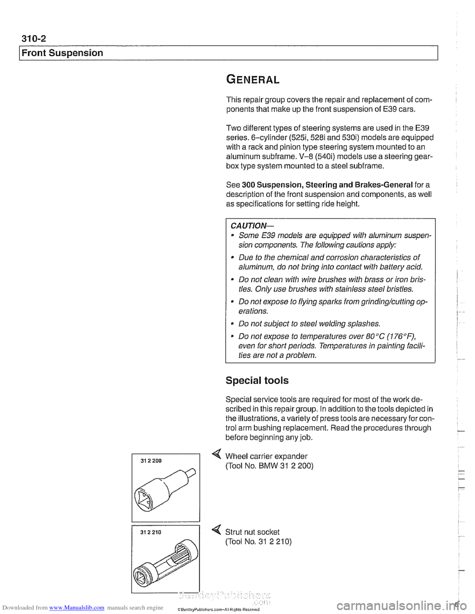
Special tools
Special service tools are required for most of the work de-
scribed in this repair group. In addition to the tools depicted in
the illustrations, avariety of press tools are necessaryfor con-
trol arm bushing replacement. Read the procedures through
before beginning any job.
31 2 210 I < Strut nut socket
(Tool No. 31 2 210)
Page 641 of 1002
Downloaded from www.Manualslib.com manuals search engine
31 0-5
Front ~uspensionl
Front strut assembly, removing and
installing
- Raise car and remove front wheel.
WARNING-
Make sure that the car is firmly supported on jack stands de-
signed for the purpose. Place jack stands underneath struc-
tural chassis points.
Do not place jack stands under
suspension
parts.
- Unbolt bralte caliper assembly, lkeeping bralte hose connect-
ed. Secure brake caliper to body with wire. Do not let it hang
from brake hose. See
340 Brakes.
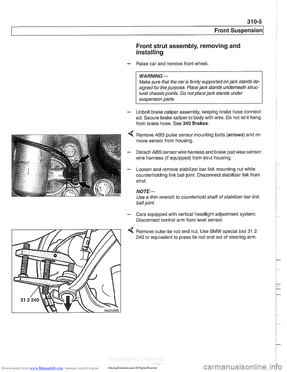
Remove ABS pulse sensor mounting bolts (arrows) and re-
move sensor from housing.
Detach ABS sensor wire harness and bralte pad wear sensor
wire harness (if equipped) from strut housing.
Loosen and remove stabilizer bar link mounting nut while
counterholding
link ball joint. Disconnect stabilizer link from
strut.
NOTE-
Use a thin wrench to counterhold shaft of stabilizer bar link
ball joint.
- Cars equipped with vertical headlight adjustment system:
Disconnect control arm from level sensor.
4 Remove outer tie rod end nut. Use BMW special tool 31 2
240 or equivalent to press tie rod end out of steering arm.
Page 654 of 1002
Downloaded from www.Manualslib.com manuals search engine
31 0-1 8
I~ront Suspension Tension strut bushing, replacing
- Raise car and remove wheel.
WARNING-
Make sure that the caris firmly supported on jack stands de-
signed for the purpose. Place jack stands underneath struc-
tural chassis points. Do
not place jack stands under
suspension parts.
- Remove tension strut from car as described earlier.
- Using a service press and appropriate press tools (BMW
special tools 31 2 26112621263 or equivalent), press bushing
out of tension strut.
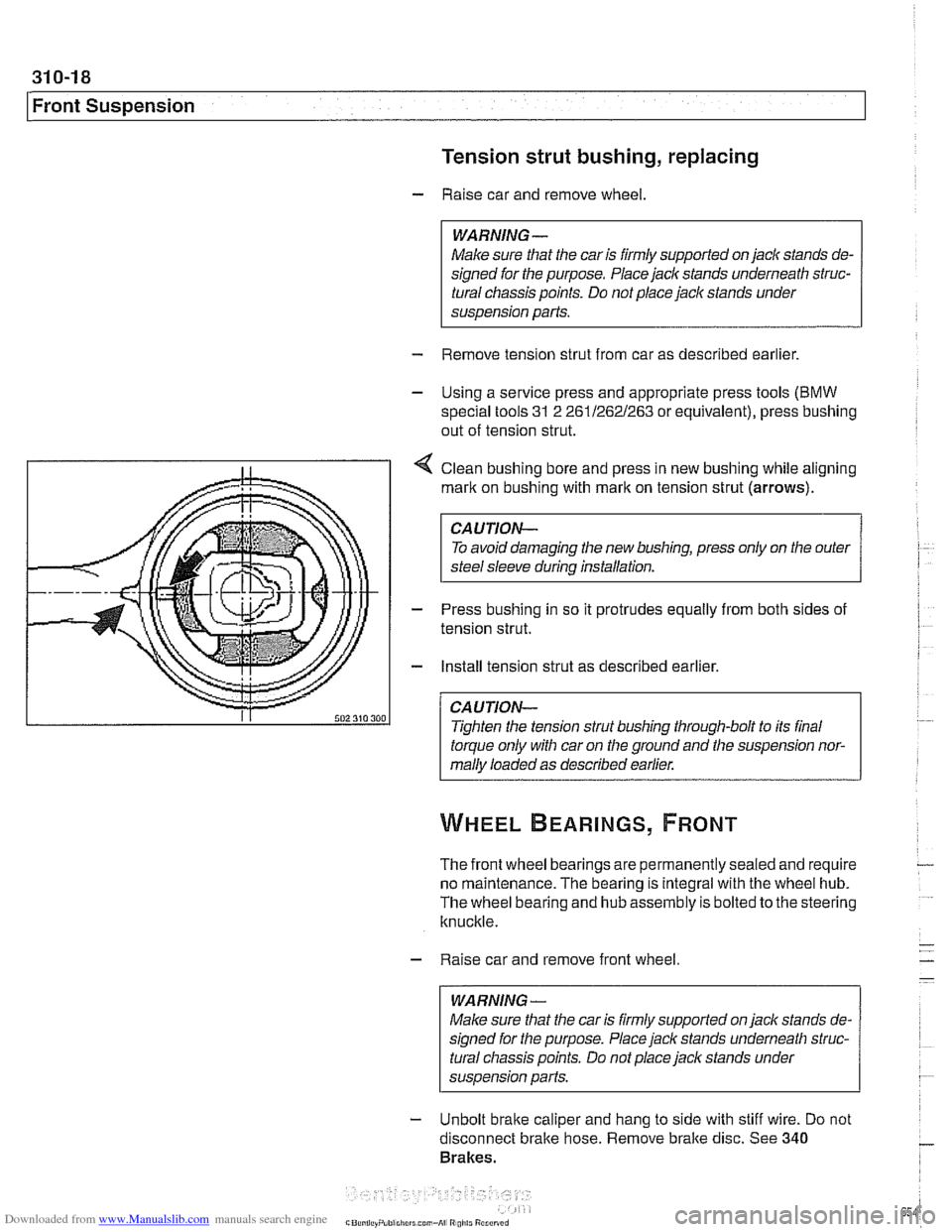
4 Clean bushing bore and press in new bushing while aligning
mark on bushing with
rnarlt on tension strut (arrows).
CAUTION-
To avoid damaging the new bushing, press only on the outer
steel sleeve during installation.
- Press bushing in so it protrudes equally from both sides of
tension strut.
- Install tension strut as described earlier.
CAUTION-
Tighten the tension strut bushing through-bolt to its final
torque only with car on the ground and the suspension nor-
mally loaded as described earlier.
The front wheel bearings are permanently sealed and require
no maintenance. The bearing is integral with the wheel hub.
The wheel bearing and hub assembly is bolted to the steering
knuckle.
- Raise car and remove front wheel
WARNING-
Make sure that the car is firmly supported on jack stands de-
signed for the purpose. Place jack stands underneath struc-
tural chassis points. Do not place
jack stands under
susoension Darts.
- Unbolt brake caliper and hang to side with stiff wire. Do not
disconnect bralte hose. Remove bralte disc. See
340
Brakes.
Page 664 of 1002
Downloaded from www.Manualslib.com manuals search engine
Steering and Wheel Alignment
Steering system warnings and cautions
WARNING -
The BMW airbag system is complex. Special precautions
must be observed when servicing the system. Serious in-
jury may result if system service is attempted by persons
unfamiliar with the BMW
airbag system and its approved
service procedures. BMW specifies that all inspection and
service should be
peiformed by an authorized BMW deal-
e,:
The BMW E39 is equipped with an airbag mounted in
the steering wheel. The
airbag is an explosive device
and should be treated with extreme caution. Always fol-
low the
airbag removal procedure as outlined in 721
Airbag System (SRS).
BMW airbags are equipped with a bacli-up power sup-
ply inside the
airbag control module. A 5 second wait-
ing period should be observed after the battery cable
has been disconnected. This will allow the reserve
power supply to discharge.
Do not reuse self-locking nuts. They are designed to
be used only once and may fail if reused. Always re-
place them with new locliing nuts.
* Do not install bolts and nuts coated with undercoating
wax, as correct tightening torque cannot be assured.
Always clean the threads with solvent before installa-
tion, or install new parts.
Do not attempt to weld or straighten any steering com-
ponents. Always replace damagedparts.
CAUTION--
- Some E39 models are equipped with aluminum suspen.
sion components. The following cautions apply:
Due to the chemical and corrosion characteristics of
aluminum, do not bring into contact with battery acid.
Do not clean with wire brushes with brass or iron bris-
tles. Only use brushes with stainless steel bristles.
Do
not expose to flying sparks from grindinghutting op-
erations.
Do not subject to steel welding splashes.
* Do not expose to temperatures over 80% (176°F).
even for short periods. Temperatures in painting iacili-
ties are not a problem.
Page 669 of 1002
Downloaded from www.Manualslib.com manuals search engine
Steering and Wheel ~li~nrnentl
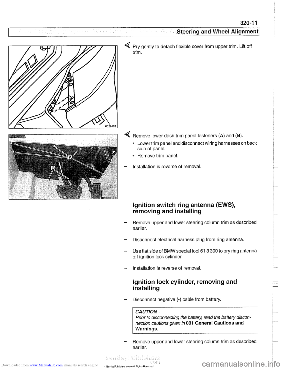
q Pry gently to detach flexible cover from upper trim. Lift off
trim.
< Remove lower dash trim panel fasteners (A) and (B).
Lower trim panel and disconnect wiring harnesses on back
side of panel.
Remove trim panel.
- Installation is reverse of removal.
Ignition switch ring antenna (EWS),
removing and installing
- Remove upper and lower steering column trim as described
earlier.
- Disconnect electrical harness plug from ring antenna.
- Use flat side of BMW special tool 61 3 300 to pry ring antenna
off ignition lock cylinder.
- Installation is reverse of removal.
lgnition lock cylinder, removing and
installing
- Disconnect negative (-) cable from battery.
CAUTION-
Prior to disconnecting the battery, read the battery discon-
nection cautions given
in 001 General Cautions and
Warnings.
- Remove upper and lower steering column trim as described
earlier.
Page 670 of 1002
Downloaded from www.Manualslib.com manuals search engine
I Steering and Wheel Alignment
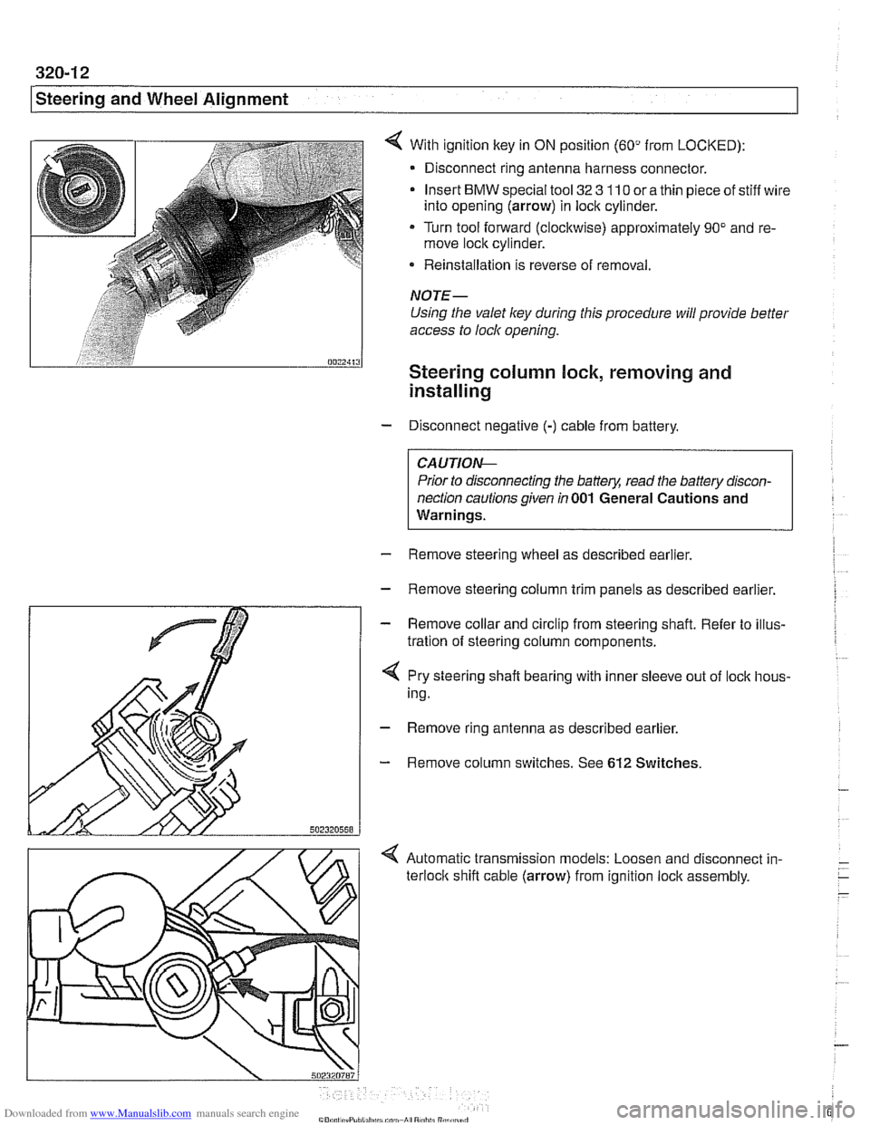
With ignition key in ON position (60" from LOCKED):
- Disconnect ring antenna harness connector.
Insert
BMW special tool 32 3 110 or a thin piece of stiff wire
into opening (arrow) in lock cylinder.
Turn tool forward (clockwise) approximately 90" and re-
move lock cylinder.
* Reinstallation is reverse of removal.
NOTE-
Using the valet ley during this procedure will provide better
access to lock opening.
Steering column lock, removing and
installing
- Disconnect negative (-) cable from battery.
CAUTIO&
Prior to disconnecting the battery, read the battery discon-
nection cautions given
in 001 General Cautions and
Warnings.
- Remove steering wheel as described earlier.
- Remove steering column trim panels as described earlier.
- Remove collar and circlip from steering shaft. Refer to illus-
tration of steering column components.
4 Pry steering shaft bearing with inner sleeve out of lock hous-
ing.
- Remove ring antenna as described earlier.
- Remove column switches. See 612 Switches.
< Automatic transmission models: Loosen and disconnect in-
terloclc shift cable (arrow) from ignition lock assembly.
Page 671 of 1002
Downloaded from www.Manualslib.com manuals search engine
Steering and Wheel Alignment
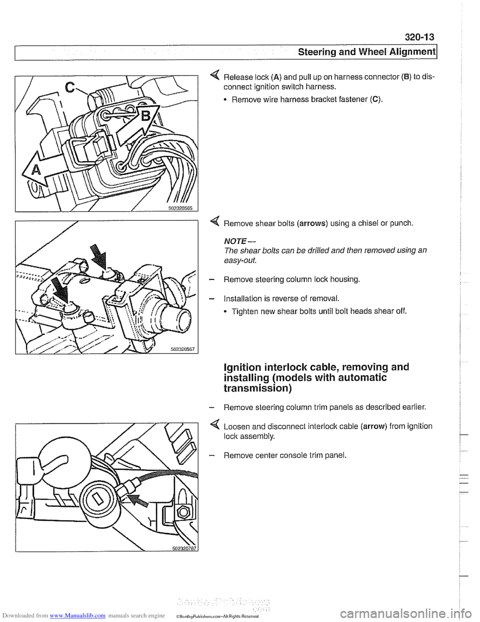
4 Release lock (A) and pull up on harness connector (6) to dis-
connect ignition switch harness.
. Remove wire harness bracket fastener (C).
4 Remove shear bolts (arrows) using a chisel or punch.
NOTE-
The shear bolts can be drilled and then removed using an
easy-out.
- Remove steering column lock housing.
- Installation is reverse of removal.
Tighten new shear bolts until bolt heads shear off.
ignition interlock cable, removing and
installing (models
with automatic
transmission)
- Remove steering column trim panels as described earlier.
4 Loosen and disconnect interlock cable (arrow) from ignition
lock assembly.
- Remove center console trim panel.