Wir BMW 540i 1997 E39 Workshop Manual
[x] Cancel search | Manufacturer: BMW, Model Year: 1997, Model line: 540i, Model: BMW 540i 1997 E39Pages: 1002
Page 501 of 1002
Downloaded from www.Manualslib.com manuals search engine
170-5
Radiator and Cooling System
Fan switch calibration (M52, M62 engine)
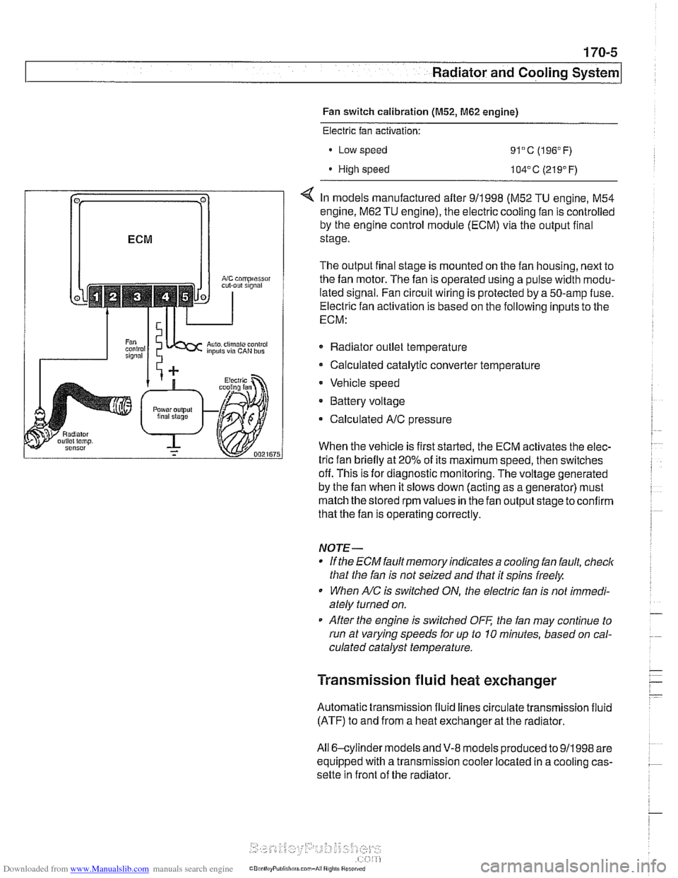
coniprairoi OUt rlgnal
Auto. ciimilte ~ontioi inpuls via CAN bus
Electric fan activation:
Low speed
91°C (196°F)
High speed 104' C (21 9' F)
< In models manufactured after 911998 (M52 TU engine, M54
engine.
M62 TU engine), the electric cooling fan is controlled
by the engine control module (ECM) via the output final
stage.
The output final stage is mounted on the fan housing, next to
the fan motor. The fan is operated using a pulse width modu-
lated signal. Fan circuit wiring is protected by a 50-amp fuse.
Electric fan activation is based on the following inputs to the
ECM:
Radiator outlet temperature
Calculated catalytic converter temperature
Vehicle speed
* Battery voltage
Calculated
A/C pressure
When the vehicle is first started, the ECM activates the elec-
tric fan briefly at 20% of its maximum speed, then switches
off. This is for diagnostic monitoring. The voltage generated
by the fan when it slows down (acting as a generator) must
match the stored rpm values in the fan output stage toconfirm
that the fan is operating correctly.
NOTE-
If the ECM fault memory indicates a cooling fan fault, check
that the fan is not seized and that it spins freely.
When
A/C is switched ON, the electric fan is not immedi-
ately turned on.
After the engine is switched
OFF the fan may continue to
run at varying speeds for up to 10 minutes, based on cal-
culated catalyst temperature.
Transmission fluid heat exchanger
Automatic transmission fluid lines circulate transmission fluid
(ATF) to and from a heat exchanger at the radiator.
All 6-cylinder
models andV-8 models produced to 911998 are
equipped with a transmission cooler located in a cooling cas-
sette in front of the radiator.
Page 506 of 1002
Downloaded from www.Manualslib.com manuals search engine
170-1 0
I Radiator and Cooling System
Combustion chamber leak test
- If you suspect that combustion chamber pressure is leaking
into the cooling system past the cylinder head gasket, use an
exhaust gas analyzer to test the vapors rising from the cool-
ant at the expansion tank.
CAUTIO&
Use an extension tube above the reservoir neclc to main-
tain distance between the top of the coolant and the gas
analyzer
nozzle. The gas analyzer is easily damaged if it is
allowed to inhale liquid coolant.
* While running engine to checlc for causes of overheat-
ing, observe coolant temperature carefully in order to
avoid engine damage.
Thermostat
If the engine overheats or runs too cool and no other cooling
system tests indicate trouble, the thermostat may be faulty.
In
V-8 models and 6-cvlinder models nroduced afler 911 998
(M52TU or M54 eng'ne), rheelecrricaily heated rhermostal IS
mon tored by [he OBD II diagnostlc software The fault may ic
in the DME software or hardware, or it may lie in the wiring to
the thermostat. See
OED On-Board Diagnostics.
Coolant, draining and filling
(6-cylinder models)
WARNING -
Allow the cooling system to cool before opening or draining
the cooling system.
- Raise front of car and support safely.
WARNING -
Make sure the car is stable and well supported at all times.
Use a professional automotive lift
orjack stands designed for
the purpose. A floor jack is not adequate support.
- Remove splash shield from under engine.
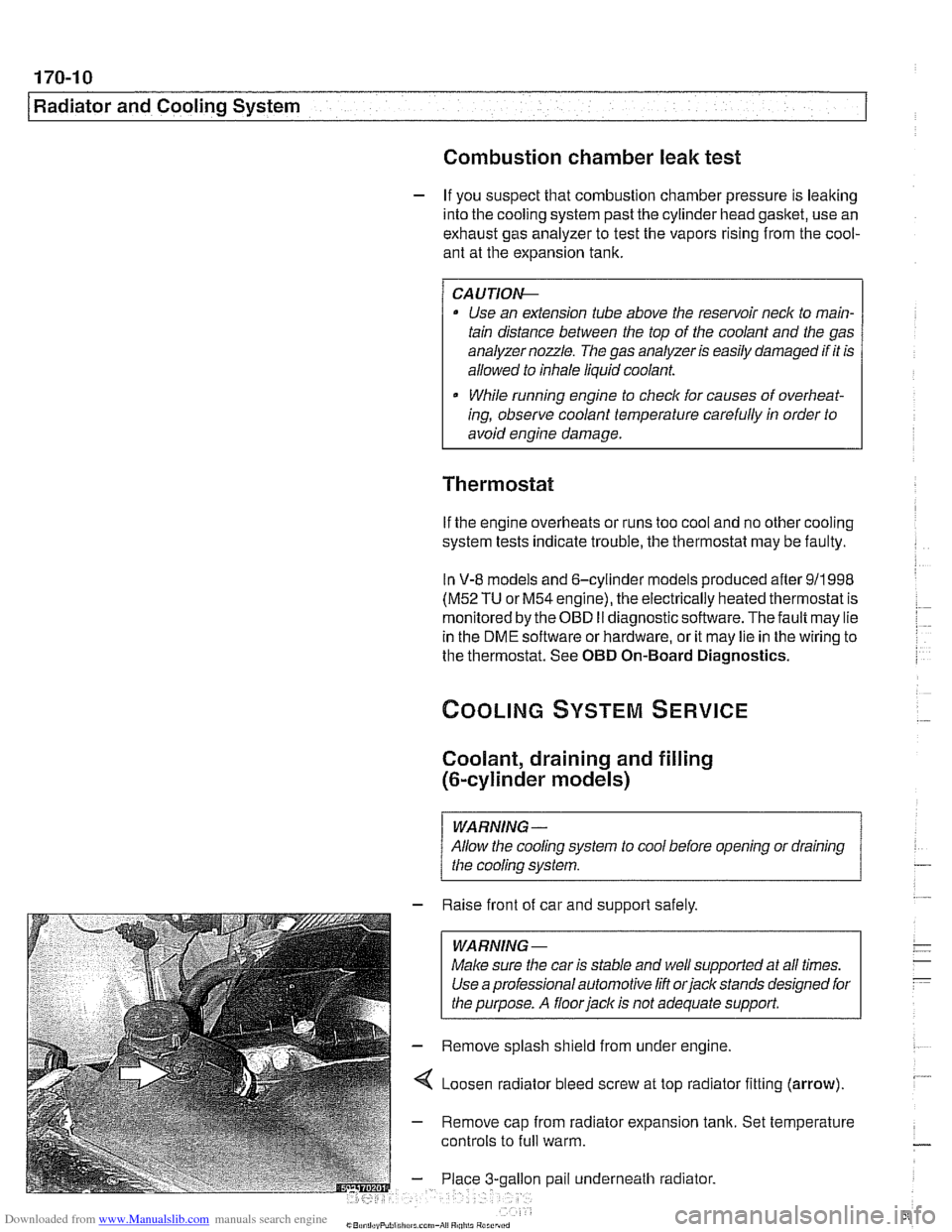
4 Loosen radiator bleed screw at top radiator fitting (arrow).
- Remove cap from radiator expansion tank. Set temperature
controls to
full warm.
gallon pail underneath radiator.
Page 511 of 1002
Downloaded from www.Manualslib.com manuals search engine
Radiator and Cooling System
Remove rubber trim strip between top of shroud and radiator.
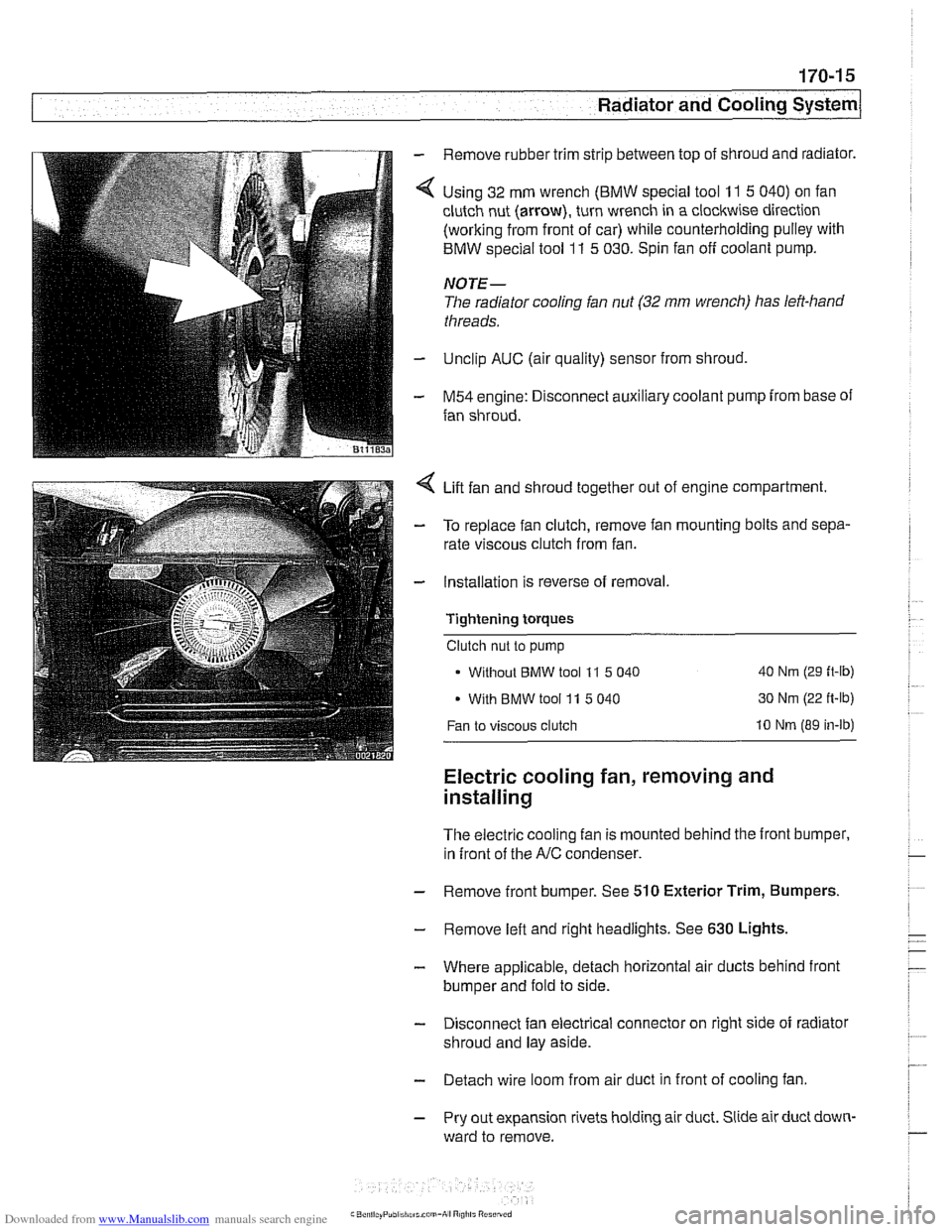
Using 32 mm wrench
(BMW special tool 11 5 040) on fan
clutch nut (arrow), turn wrench in a clockwise direction
(working from front of car) while counterholding pulley with
BMW special tool
11 5 030. Spin fan off coolant pump.
NOTE-
The radiator cooling fan nut (32 mm wrench) has left-hand
threads.
Unclip AUC (air quality) sensor from shroud,
M54 engine: Disconnect auxiliary coolant pump from base of
fan shroud.
Lift fan and shroud together out of engine compartment.
To replace fan clutch, remove fan mounting bolts and sepa-
rate viscous clutch from fan.
Installation is reverse of removal.
Tightening
torques
Clutch nut to pump
Without
BMW tool 11 5 040 40 Nm (29 ft-lb)
With BMW tool 11 5 040 30 Nm
(22 ft-lb)
Fan to viscous clutch 10 Nm (89 in-lb)
Electric cooling fan, removing and
installing
The electric cooling fan is mounted behind the front bumper,
in front of the
A/C condenser.
- Remove front bumper. See 510 Exterior Trim, Bumpers.
- Remove left and right headlights. See 630 Lights,
- Where applicable, detach horizontal air ducts behind front
bumper and fold to side.
- Disconnect fan electrical connector on right side of radiator
shroud and lay aside.
- Detach wire loom from air duct in front of cooling fan
- Pry out expansion rivets holding air duct. Slide air duct down-
ward to remove.
Page 512 of 1002
Downloaded from www.Manualslib.com manuals search engine
170-1 6
I Radiator and Cooling System
- Remove fan and fan shroud mounting fasteners. Slide fan
and fan shroud downward to remove.
- Reinstallation is reverse of removal.
Thermostat, removing and installing
(M52 engine)
The coolant thermostat is installed in a housing at the front of
the engine.
- Drain coolant from radiator and engine block. See Coolant,
draining and filling (6-cylinder models).
WARNING -
Allow the cooling system to cool before opening or draining
the system.
- Remove mechanical cooling fan and fan shroud. See Me-
chanical (viscous clutch) cooling fan, removing and in-
stalling.
- Disconnect coolant hoses from thermostat housing.
- Remove thermostat housing from front of engine.
- Remove thermostat. Note thermostat direction and orienta-
tion before removing.
- Installation is reverse of removal, noting the following:
- Use new O-ring and gasket(s) when installing thermostat
and housing.
NOTE-
Some thermostats have a direction arrow or vent hole near
the edge. Install the thermostat so that either the arrow or
hole are at the top.
Fill system with coolant as described in Coolant, draining
and filling (6-cylinder models).
CAUTION-
Be sure to reconnect ground wire@) at thermostat housing
mounting bolt, where applicable.
Page 549 of 1002
Downloaded from www.Manualslib.com manuals search engine
21 0-7
Clutch
- Remove brake fluid reservoir cap. Using a clean syringe.
remove brake fluid from reservoir to below level of clutch
hydraulic supply hose.
- Detach clutch hydraulic supply hose from brake fluid reser-
voir. Plug reservoir outlet and hose.
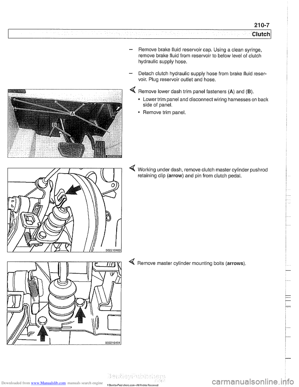
4 Remove lower dash trim panel fasteners (A) and (B).
Lower trim panel and disconnect wiring harnesses on back
side of panel.
Remove trim panel.
4 Working under dash, remove clutch master cylinder pushrod
retaining clip (arrow) and pin from clutch pedal.
4 Remove master cylinder mounting bolts (arrows)
Page 571 of 1002
Downloaded from www.Manualslib.com manuals search engine
230-7
Manual Transmission
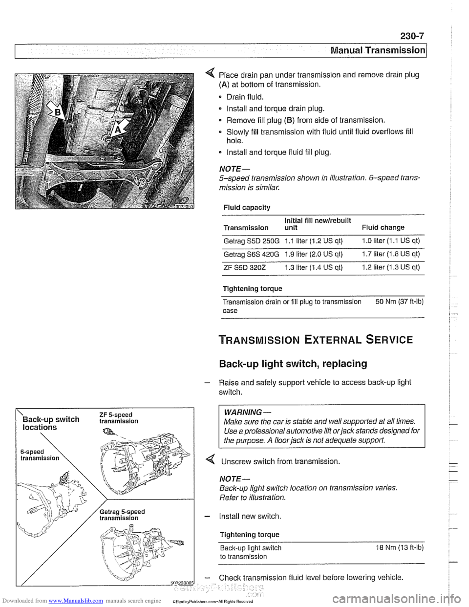
Place drain pan under transmission and remove drain plug
(A) at bottom of transmission.
Drain fluid.
lnstall and torque drain plug.
Remove fill plug
(6) from side of transmission.
Slowly fill transmission with fluid until fluid overflows fill
hole.
lnstall and torque fluid fill
plug.
NOJE-
5-speed transmission shown in illustration. 6-speed trans-
mission is similar.
Fluid capacity
Initial fill
newirebuilt Transmission unit Fluid change
Getrag S5D 250G 1.1 liter (1.2 US qt) 1.0 liter (1 .l US qt)
Getrag S6S 420G 1.9 liter (2.0 US qt) 1.7 liter (1.8 US qt)
ZF S5D 3202 1.3 liter (1.4 US at) 1.2 liter (1.3 US qt)
Tightening torque
Transmission drain or
fill plug to transmission 50
Nm (37 ft-lb)
case
Back-up light switch, replacing
- Raise and safely support vehicle to access back-up light
switch.
WARNING -
4 Unscrew switch from transmission.
Back-up light switch location on transmission varies.
Refer to illustration.
- Install new switch.
Tightening torque Back-up light switch
18 Nm (13 ft-lb)
to transmission
ission fluid level before lowering vehicle.
Page 582 of 1002
Downloaded from www.Manualslib.com manuals search engine
230-1 8
Manual Transmission
- Unbolt clutch slave cylinder from side of transmission. Do not
disconnect fluid hose. Suspend slave cylinder from chassis
using stiff wire.
CA UTIOG
Unbolt clutch slave cylinder slowly to prevent air being
drawn into hydraulic system.
. Do not operate clutch pedal with slave cylinder re-
moved from transmission.
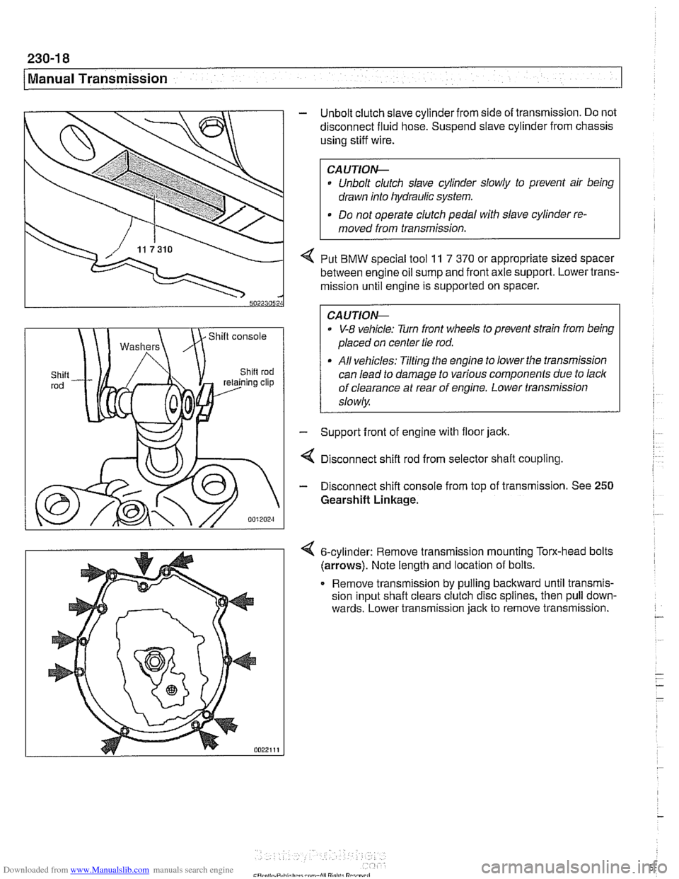
4 Put BMW special tool 11 7 370 or appropriate sized spacer
between engine oil sump and front axle support. Lower trans-
mission until engine is supported on spacer.
0 V-8 vehicle: Turn front wheels to prevent strain from being
placed on center tie rod.
All vehicles: Tilting the engine to lower the transmission
can lead to damage to various components due to lack
of clearance at rear of engine. Lower transmission
slowly
- Support front of engine with floor jack.
4 Disconnect shift rod from selector shaft coupling
- Disconnect shift console from top of transmission. See 250
Gearshift Linkage.
6-cylinder: Remove transrnisslon mounting Torx-head bolts
(arrows). Note length and locatlon of bolts.
Remove
transrnlssion by pulling backward untll transmls-
sion Input shaft clears clutch d~sc spl~nes, then pull down-
wards. Lower
transmlsslon jack to remove transrnlsslon. -
- - -
-
Page 595 of 1002
Downloaded from www.Manualslib.com manuals search engine
Automatic ~ransmissionl
II I
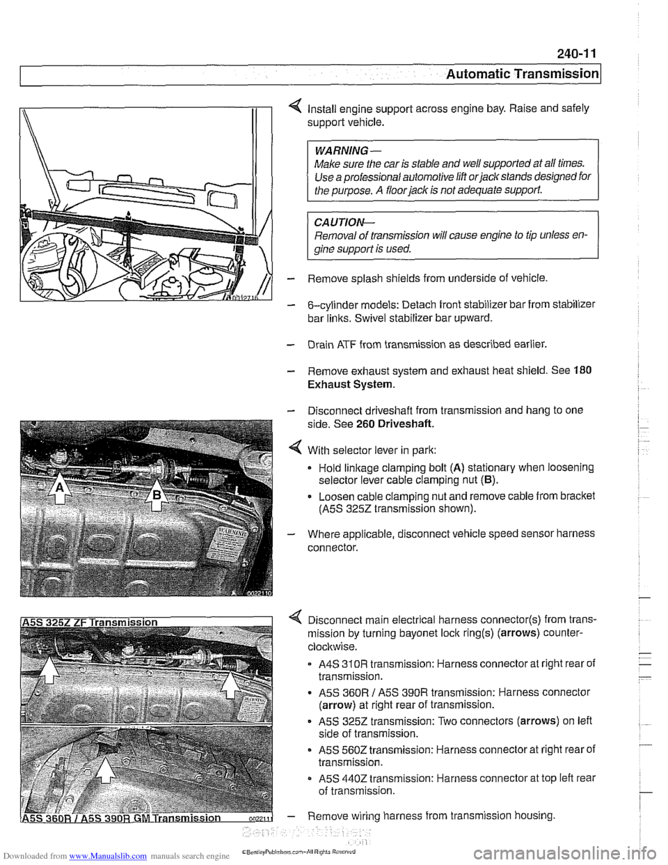
4 Install engine support across engine bay. Raise and safely
support vehicle.
Make sure the car is stable and
we1 supported at all times.
Use a professional automotive lift
orjaclc stands designed for
CAUTIOI\C
Removal of transmission will cause engine to tip unless en-
gine support is used.
- Remove splash shields from underside of vehicle.
- &cylinder models: Detach front stabilizer bar from stabilizer
bar
links. Swivel stabilizer bar upward.
- Drain ATF from transmission as described earlier.
- Remove exhaust system and exhaust heat shield. See 180
Exhaust System.
- Disconnect driveshaft from transmission and hang to one
side. See
260 Driveshaft.
4 With selector lever in park:
Hold
linkage clamping bolt (A) stationary when loosening
selector lever cable clamping nut
(6).
- Loosen cable clamping nut and remove cable from bracket
(ASS
3252 transmission shown).
- Where applicable, disconnect vehicle speed sensor harness
connector.
4 Disconnect main electrical harness connector(s) from trans-
mission by turning bayonet lock
ring(s) (arrows) counter-
clocltwise.
A4S
310R transmission: Harness connector at right rear of
transmission.
ASS
360R / ASS 390R transmission: Harness connector
(arrow) at right rear of transmission.
ASS 3252 transmission: Two connectors (arrows) on left
side of transmission.
ASS 5602 transmission: Harness connector at right rear of
transmission.
- ASS 4402 transmission: Harness connector at top left rear
of transmission.
- Remove wiring harness from transmission housing
Page 605 of 1002
Downloaded from www.Manualslib.com manuals search engine
250-7
Gearshift ~inka~el
Automatic shiftlock, checking function (automatic transmission)
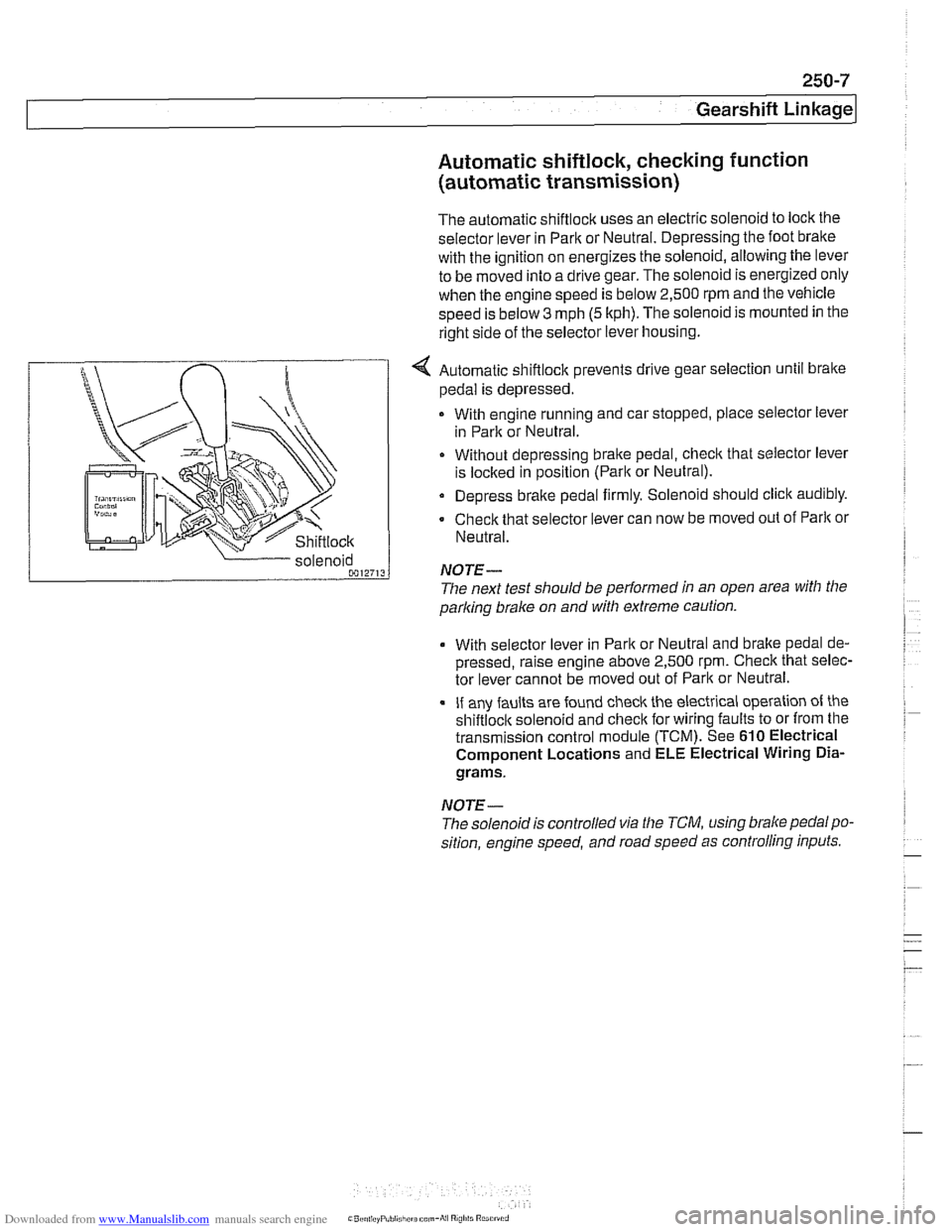
The automatic shiftlock uses an electric solenoid to lock the
selector lever in Park or Neutral. Depressing the foot bralte
with the ignition on energizes the solenoid, allowing the lever
to be moved into a drive gear. The solenoid is energized only
when the engine speed is below 2,500 rpm and the vehicle
speed is below
3 mph (5 kph). The solenoid is mounted in the
right side of the selector lever housing.
... nir r
Shiftlock
4 Automatic shiftlock prevents drive gear selection until brake
pedal is depressed.
With engine running and car stopped, place selector lever
in Park or Neutral.
Without depressing bralte pedal, check that selector lever
is
loclted in position (Parlt or Neutral).
Depress brake pedal firmly. Solenoid should click audibly.
Check that selector lever can now be moved out of
Parlt or
Neutral.
parking
brake on and with extreme caution.
solenoid
0012713
With selector
lever in Park or Neutral and bralte pedal de-
pressed, raise engine above 2,500
rpm. Check that selec-
tor lever cannot be moved out of Park or Neutral.
If any faults are found check the electrical operation of the
shiftloclt solenoid and checlt for wiring faults to or from the
transmission control module (TCM). See
610 Electrical
Component Locations and ELE Electrical Wiring
Dia-
grams.
NOTE-
NOTE-
The solenoidis controlled via the TCM, using brake pedalpo-
sition, engine speed, and road speed as controlling inputs.
The
next test should be performed in an open area with the
Page 614 of 1002
Downloaded from www.Manualslib.com manuals search engine
-.- .
/ Driveshaft Driveshaft, removing
CAUTION-
. Be sure the wheels are off the ground before removing the
driveshak Set the parl(ing brake before removing the
driveshaft.
Once the driveshaft has been removed, the vehicle can
roll regardless of whether the transmission is in gear or
not.
The driveshaft is mounted to the transmission and final
drive
with self-locliing nuts. These nuts are designed to
be used only once and should be replaced during reas-
sembly.
Remove complete exhaust system. See
180 Exhaust
System.
- Remove exhaust heat shields.
- Support transmission with transmission jack.
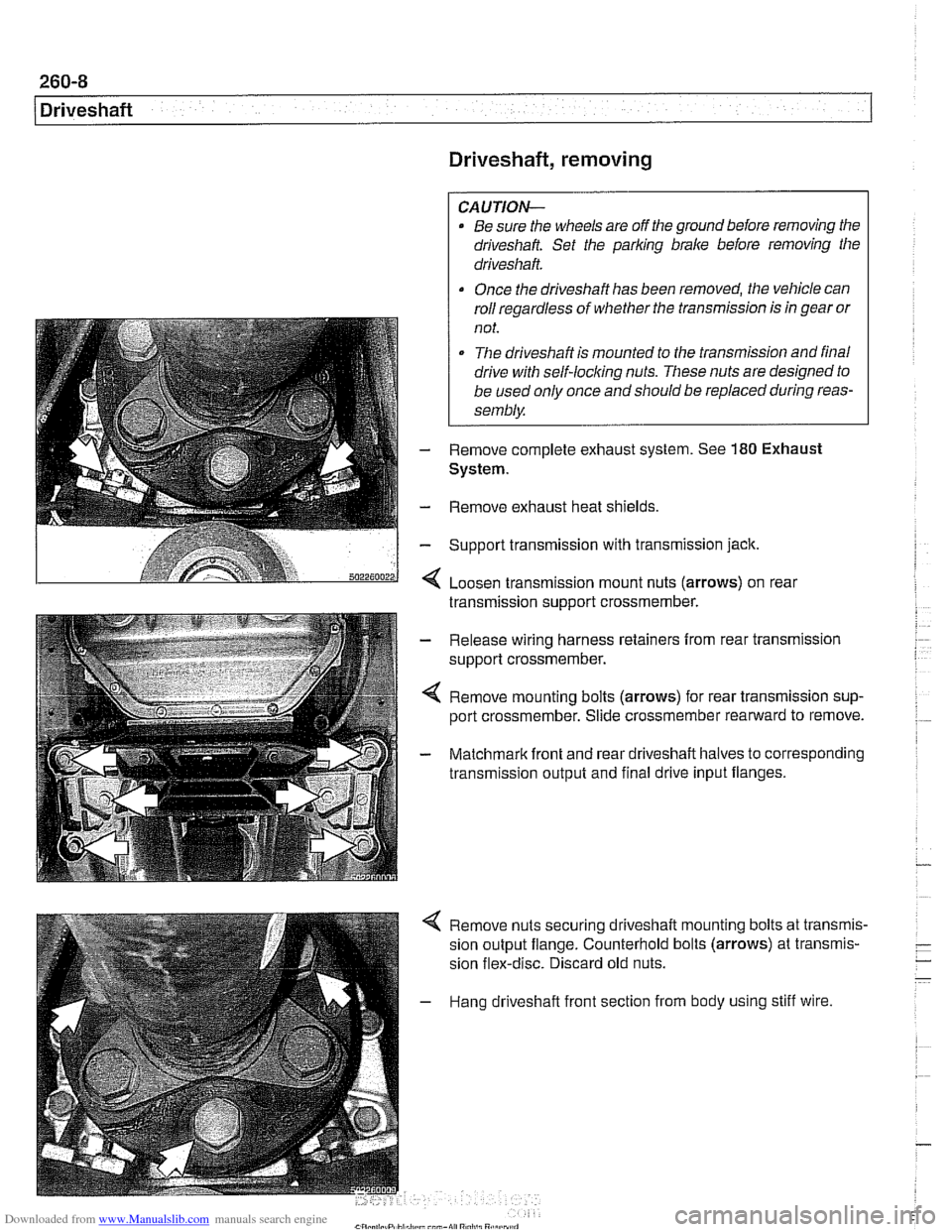
< Loosen transmission mount nuts (arrows) on real
transmission support crossmember.
- Release wiring harness retainers from rear transmission
support crossmember.
< Remove mounting bolts (arrows) for rear transmission sup-
port crossmember. Slide crossmember rearward to remove.
- Matchmark front and rear driveshaft halves to corresponding
transmission output and final drive input flanges.
4 Remove nuts securing driveshaft mounting bolts at transmis-
sion output flange. Counterhold bolts (arrows) at transmis-
sion flex-disc. Discard old nuts.
- Hang driveshaft front section from body using stiff wire.