BMW MOTORRAD K 1200 R 2008 Rider's Manual (in English)
Manufacturer: BMW MOTORRAD, Model Year: 2008, Model line: K 1200 R, Model: BMW MOTORRAD K 1200 R 2008Pages: 165, PDF Size: 2.18 MB
Page 111 of 165
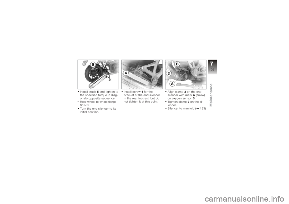
Install studs5and tighten to
the specified torque in diag-
onally opposite sequence.
Rear wheel to wheel flange
60 Nm
Turn the end silencer to its
initial position. Install screw
4for the
bracket of the end silencer
in the rear footrest, but do
not tighten it at this point. Align clamp
3on the end
silencer with mark A(arrow)
on oxygen sensor B.
Tighten clamp 3on the si-
lencer.
Silencer to manifold ( 133)
7109zMaintenance
Page 112 of 165
If the gap between the
rear wheel and the end
silencer is too small, the rear
wheel can overheat.
The clearance between the
rear wheel and the end silen-
cer must be at least 15 mm.
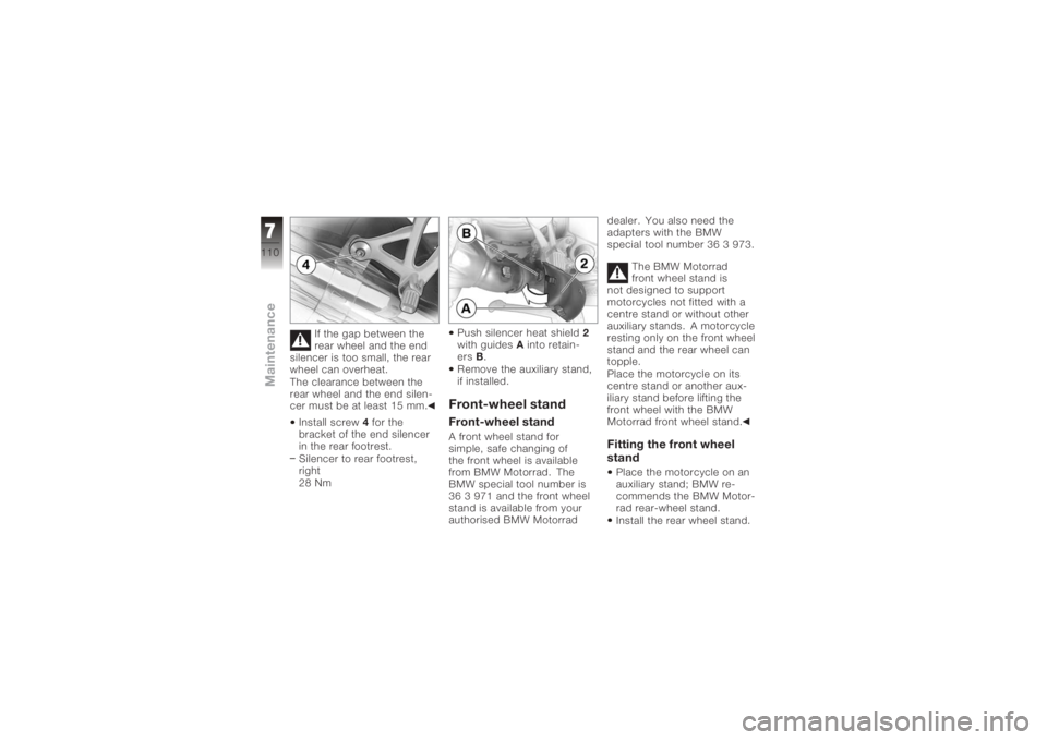
Install screw 4for the
bracket of the end silencer
in the rear footrest.
Silencer to rear footrest,
right
28 Nm Push silencer heat shield
2
with guides Ainto retain-
ers B.
Remove the auxiliary stand,
if installed.
Front-wheel standFront-wheel standA front wheel stand for
simple, safe changing of
the front wheel is available
from BMW Motorrad. The
BMW special tool number is
36 3 971 and the front wheel
stand is available from your
authorised BMW Motorrad dealer. You also need the
adapters with the BMW
special tool number 36 3 973.
The BMW Motorrad
front wheel stand is
not designed to support
motorcycles not fitted with a
centre stand or without other
auxiliary stands. A motorcycle
resting only on the front wheel
stand and the rear wheel can
topple.
Place the motorcycle on its
centre stand or another aux-
iliary stand before lifting the
front wheel with the BMW
Motorrad front wheel stand.
Fitting the front wheel
standPlace the motorcycle on an
auxiliary stand; BMW re-
commends the BMW Motor-
rad rear-wheel stand.
Install the rear wheel stand.
7110zMaintenance
Page 113 of 165
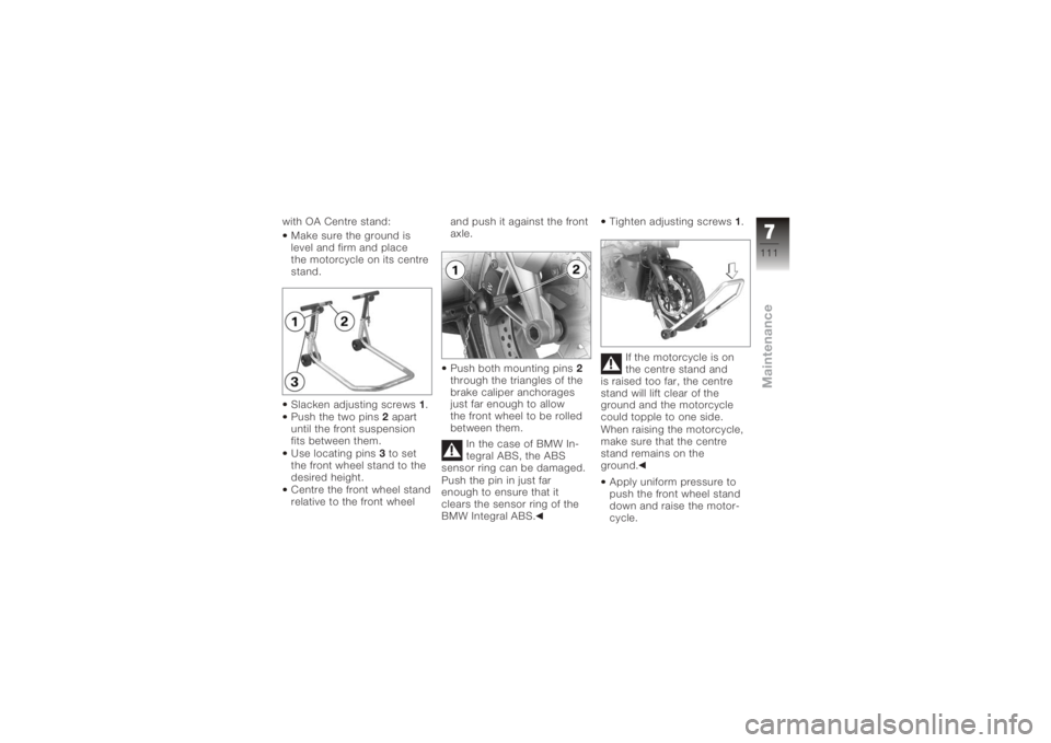
with OA Centre stand:Make sure the ground is
level and firm and place
the motorcycle on its centre
stand.
Slacken adjusting screws 1.
Push the two pins 2apart
until the front suspension
fits between them.
Use locating pins 3to set
the front wheel stand to the
desired height.
Centre the front wheel stand
relative to the front wheel and push it against the front
axle.
Push both mounting pins
2
through the triangles of the
brake caliper anchorages
just far enough to allow
the front wheel to be rolled
between them.
In the case of BMW In-
tegral ABS, the ABS
sensor ring can be damaged.
Push the pin in just far
enough to ensure that it
clears the sensor ring of the
BMW Integral ABS. Tighten adjusting screws
1.
If the motorcycle is on
the centre stand and
is raised too far, the centre
stand will lift clear of the
ground and the motorcycle
could topple to one side.
When raising the motorcycle,
make sure that the centre
stand remains on the
ground.
Apply uniform pressure to
push the front wheel stand
down and raise the motor-
cycle.
7111zMaintenance
Page 114 of 165
Rear wheel standRear wheel standBMW Motorrad offers an aux-
iliary stand for holding mo-
torcycles (including those
without centre stands) se-
curely upright for mainten-
ance work. The BMW special
tool number is 36 3 980 and
the auxiliary stand is avail-
able from your authorised
BMW Motorrad dealer.
Fitting the rear wheel
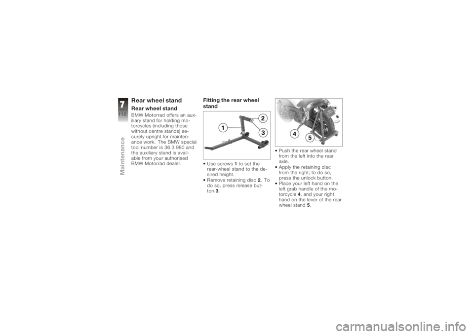
standUse screws1to set the
rear-wheel stand to the de-
sired height.
Remove retaining disc 2.To
do so, press release but-
ton 3. Push the rear wheel stand
from the left into the rear
axle.
Apply the retaining disc
from the right; to do so,
press the unlock button.
Place your left hand on the
left grab handle of the mo-
torcycle
4, and your right
hand on the lever of the rear
wheel stand 5.
7112zMaintenance
Page 115 of 165
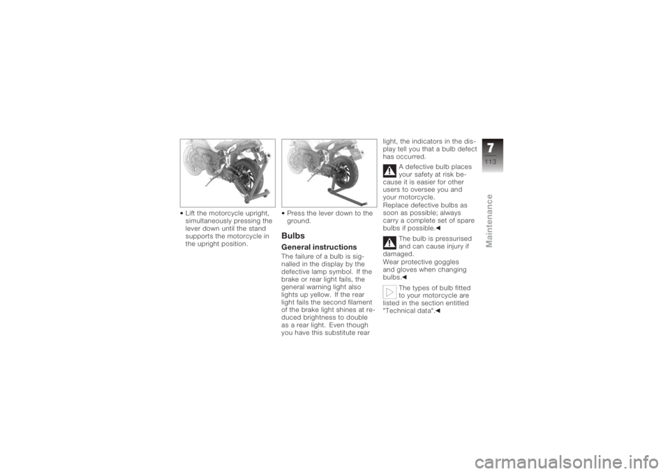
Lift the motorcycle upright,
simultaneously pressing the
lever down until the stand
supports the motorcycle in
the upright position.Press the lever down to the
ground.
BulbsGeneral instructionsThe failure of a bulb is sig-
nalled in the display by the
defective lamp symbol. If the
brake or rear light fails, the
general warning light also
lights up yellow. If the rear
light fails the second filament
of the brake light shines at re-
duced brightness to double
as a rear light. Even though
you have this substitute rearlight, the indicators in the dis-
play tell you that a bulb defect
has occurred.
A defective bulb places
your safety at risk be-
cause it is easier for other
users to oversee you and
your motorcycle.
Replace defective bulbs as
soon as possible; always
carry a complete set of spare
bulbs if possible.
The bulb is pressurised
and can cause injury if
damaged.
Wear protective goggles
and gloves when changing
bulbs.
The types of bulb fitted
to your motorcycle are
listed in the section entitled
"Technical data".
7113zMaintenance
Page 116 of 165
Do not touch the glass
of new bulbs with your
fingers. Use a clean, dry cloth
to hold the bulbs when hand-
ling them. Dirt deposits, in
particular oil and grease, in-
terfere with heat radiation
from the bulb. This leads to
overheating and shortens the
bulb's operating life.
Low-beam and
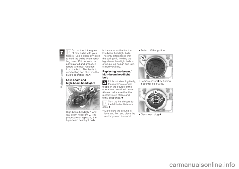
high-beam headlightsHigh-beam headlight 1and
low-beam headlight 2. The
procedure for replacing the
high-beam headlight bulb is the same as that for the
low-beam headlight bulb.
The only difference is that
the spring clip holding the
high-beam headlight bulb is
of single-leg design and is in-
stalled vertically.
Replacing low-beam /
high-beam headlight
bulb
If it is not standing firmly,
the motorcycle could
topple in the course of the
operations described below.
Always make sure that the
motorcycle is stable and
firmly supported.
Turn the handlebars to
the left to facilitate ac-
cess.
Make sure the ground is
level and firm and place the
motorcycle on its stand. Switch off the ignition.
Remove cover
3by turning
it counter-clockwise.
Disconnect plug 4.
7114zMaintenance
Page 117 of 165
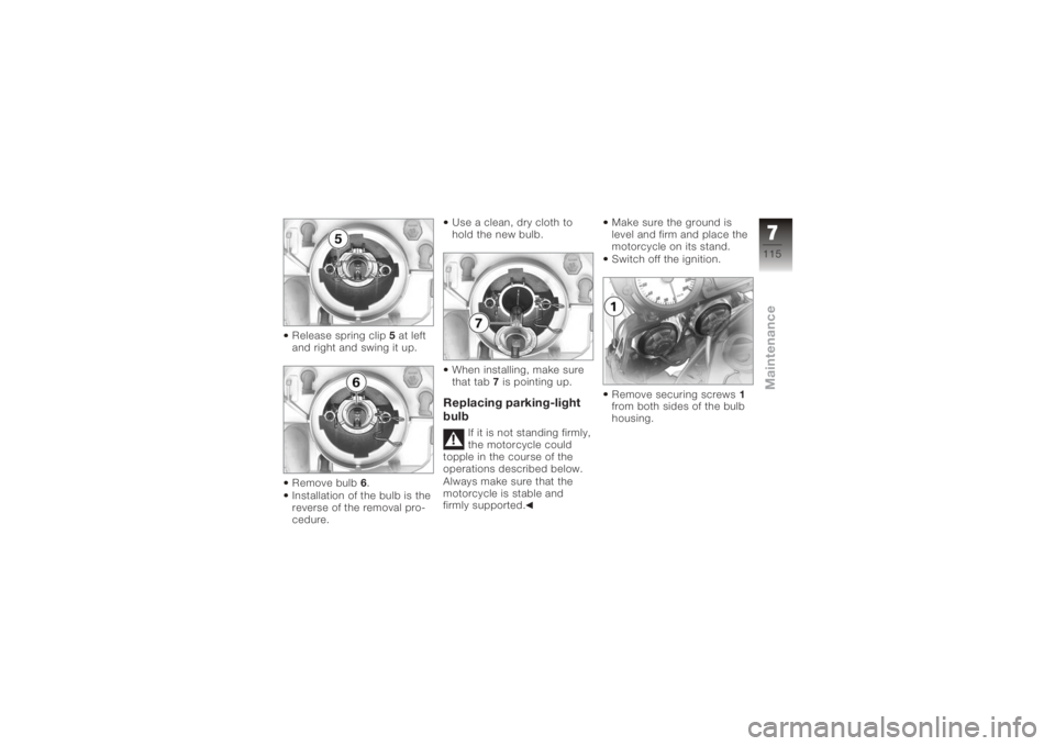
Release spring clip5at left
and right and swing it up.
Remove bulb 6.
Installation of the bulb is the
reverse of the removal pro-
cedure. Use a clean, dry cloth to
hold the new bulb.
When installing, make sure
that tab
7 is pointing up.
Replacing parking-light
bulb
If it is not standing firmly,
the motorcycle could
topple in the course of the
operations described below.
Always make sure that the
motorcycle is stable and
firmly supported. Make sure the ground is
level and firm and place the
motorcycle on its stand.
Switch off the ignition.
Remove securing screws
1
from both sides of the bulb
housing.
7115zMaintenance
Page 118 of 165
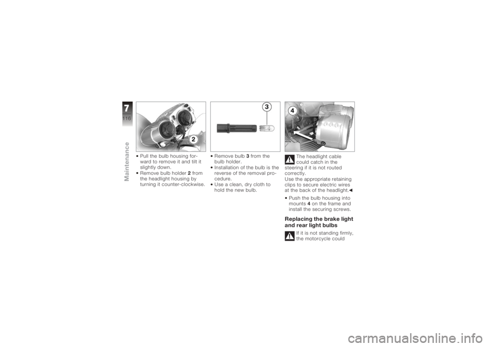
Pull the bulb housing for-
ward to remove it and tilt it
slightly down.
Remove bulb holder2from
the headlight housing by
turning it counter-clockwise. Remove bulb
3from the
bulb holder.
Installation of the bulb is the
reverse of the removal pro-
cedure.
Use a clean, dry cloth to
hold the new bulb. The headlight cable
could catch in the
steering if it is not routed
correctly.
Use the appropriate retaining
clips to secure electric wires
at the back of the headlight.
Push the bulb housing into
mounts 4on the frame and
install the securing screws.
Replacing the brake light
and rear light bulbs
If it is not standing firmly,
the motorcycle could
7116zMaintenance
Page 119 of 165
topple in the course of the
operations described below.
Always make sure that the
motorcycle is stable and
firmly supported.Make sure the ground is
level and firm and place the
motorcycle on its stand.
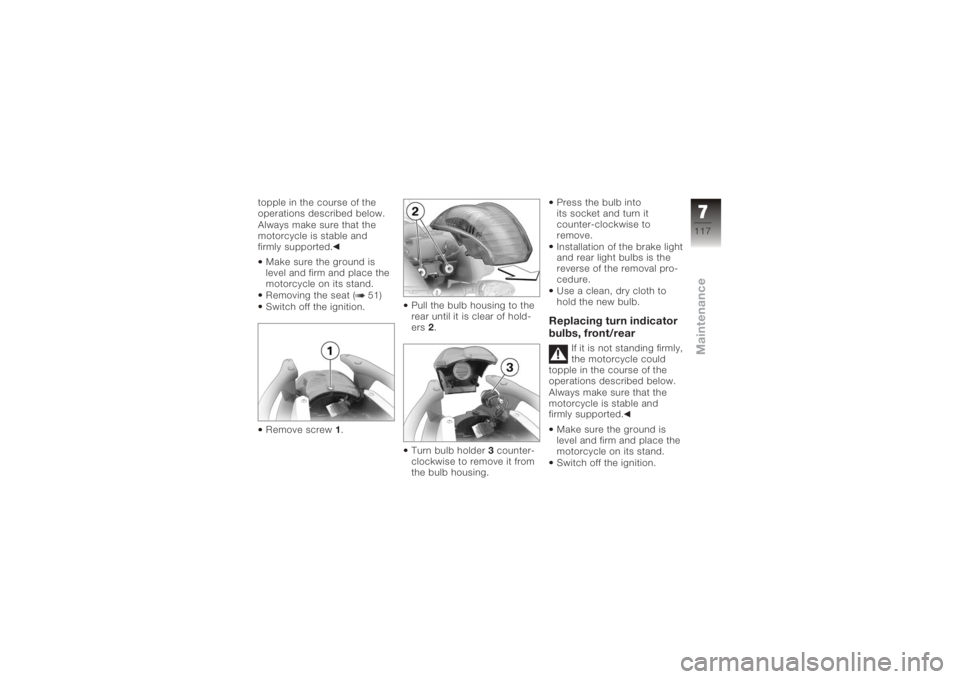
Removing the seat ( 51)
Switch off the ignition.
Remove screw 1. Pull the bulb housing to the
rear until it is clear of hold-
ers
2.
Turn bulb holder 3counter-
clockwise to remove it from
the bulb housing. Press the bulb into
its socket and turn it
counter-clockwise to
remove.
Installation of the brake light
and rear light bulbs is the
reverse of the removal pro-
cedure.
Use a clean, dry cloth to
hold the new bulb.
Replacing turn indicator
bulbs, front/rear
If it is not standing firmly,
the motorcycle could
topple in the course of the
operations described below.
Always make sure that the
motorcycle is stable and
firmly supported.
Make sure the ground is
level and firm and place the
motorcycle on its stand.
Switch off the ignition.
7117zMaintenance
Page 120 of 165
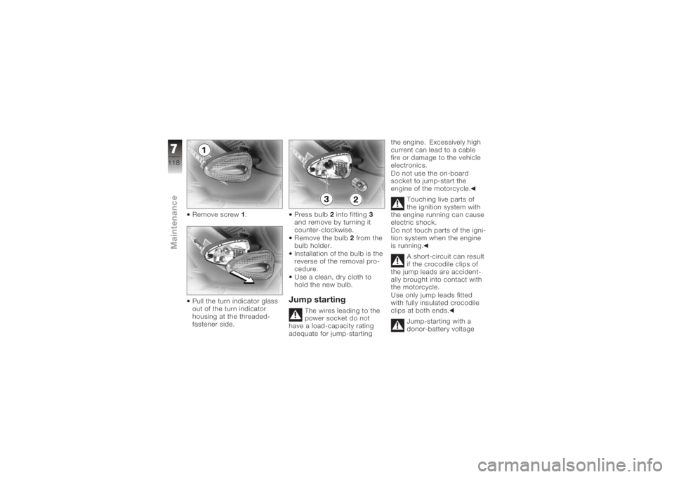
Remove screw1.
Pull the turn indicator glass
out of the turn indicator
housing at the threaded-
fastener side. Press bulb
2into fitting 3
and remove by turning it
counter-clockwise.
Remove the bulb 2 from the
bulb holder.
Installation of the bulb is the
reverse of the removal pro-
cedure.
Use a clean, dry cloth to
hold the new bulb.
Jump starting
The wires leading to the
power socket do not
have a load-capacity rating
adequate for jump-starting the engine. Excessively high
current can lead to a cable
fire or damage to the vehicle
electronics.
Do not use the on-board
socket to jump-start the
engine of the motorcycle.
Touching live parts of
the ignition system with
the engine running can cause
electric shock.
Do not touch parts of the igni-
tion system when the engine
is running.
A short-circuit can result
if the crocodile clips of
the jump leads are accident-
ally brought into contact with
the motorcycle.
Use only jump leads fitted
with fully insulated crocodile
clips at both ends.
Jump-starting with a
donor-battery voltage
7118zMaintenance