CADILLAC DEVILLE 1994 7.G Owners Manual
Manufacturer: CADILLAC, Model Year: 1994, Model line: DEVILLE, Model: CADILLAC DEVILLE 1994 7.GPages: 399, PDF Size: 20.97 MB
Page 331 of 399
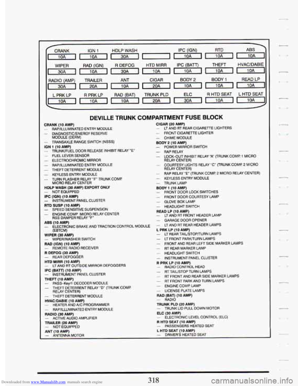
Downloaded from www.Manualslib.com manuals search engine IGN 1 HDLP WASH IPC (IGN) RTD
~~l~~~mm
WIPER RAD (IGN) R DEFOG HTD MlRR IPC (BATT) THEFT HVAC/DABIE
CIGAR BODY
2 BODY 1 READ LP
L PRK LP
R PRK LP RAD (BAT) TRUNK PLD R HTD SEAT L HTD SEAT
DEVILLE TRUNK COMPARTMENT FUSE BLOCK
CRANK (10 AMP)
- DlAGNOSTlClENERGY RESERVE
- TRANSAXLE RANGE SWITCH (NSSS)
- RAP/ILLUMINATED ENTRY MODULE
MODULE (DERM)
ION 1 (10 AMP) - TRUNWFUEL DOOR RELEASE INHIBIT RELAY "E" - FUEL LEVER SENSOR - ELECTROCHROMIC MIRROR - RAP/ILLUMINATED ENTRY MODULE - THEFT DETERRENT MODULE - KEYLESS ENTRY MODULE - TURN FLASHER RELAY "F TRUNK COMP.
HDLP WASH (30 AMP) EXPORT ONLY
IPC
(ION) (10 AMP) - INSTRUMENT PANEL CLUSTER RTD SUSP (10 AMP)
- ENGINE COMP MICRO REL4Y CENTER
ABS (IO AMP) - ELECTRONIC BRAKE AND TRACTION CONTROL MODULE
(EBTCM)
WIPER (30 AMP) - WIPERMASHER SWITCH RAD (IGN) (10 AMP)
R DEFOG (30 AMP) - REAR DEFOGGER HTD MlRR (10 AMP) - LTAND RT OUTSIDE MIRROR DEFOGGERS IPC (BATr) (10 AMP)
THEFT
(10 AMP) - PASS-Key@ DECODER MODULE - THEFT DETERRENT RELAY "D" (TRUNK COMP.
- THEFT DETERRENT MODULE HVAC/DABIE (10 AMP) - HEATER AND A/C PROGRAMMER
RADIO (30 AMP) - ACTIVE AUDIO AMPLIFIER TRAILER (20 AMP)
ANT
I10 AMP)
MICRO RELAY CENTER
- NOT EQUIPPED
- SPEED SENSITIVE SUSPENSION
RSS DAMPER RELAY "F"
- REMOTE RADIO RECEIVER
- INSTRUMENT PANEL CLUSTER
RELAY CENTER)
- RAP/ILLUMINATED ENTRY MODULE
- NOT EQUIPPED
CIGAR (20 AMP) - LT AND RT REAR CIGARETTE LIGHTERS - FRONT CIGARETTE LIGHTER - CHIME MODULE BODY 2 (10 AMP) - POWER MIRROR SWITCH - RAPRELAY - LOCK-OUT INHIBIT RELAY "A" (TRUNK COMP 1 MICRO
- COURTESY LIGHTS RELAY "C" (TRUNK COME 2 MICRO
RELAY CENTER)
RELAY CENTER)
- RAP RELAY "E (TRUNK COMP. 2 MICRO
RELAY CENTER) - KEYLESS ENTRY MODULE - TRUNKLAMP
- FRONT DOOR LOCK SWITCHES BODY 1 (10 AMP)
- FRONT DOOR COURTESY LAMP - GLOVE BOX LAMP - HEADLIGHT SWITCH READ LP (10 AMP) - LTAND AT FRONT HEADER LAMP - GARAGE DOOR OPENER - LT AND RT REAR HEADER LAMPS L PRK LP (10 AMP) - LT REAR TAlUSTOPrURN LAMPS
- FRONT AND REAR LEFT SIDE MARKER LAMPS - RT REAR MARKER LAMP - HEADLIGHT SWITCH - INSTRUMENT PANEL CLUSTER R PRK LP (10 AMP) - RADIO CONTROL HEAD - RT TAIUSTOP TURN LAMPS - RT FRONT AND REAR SIDE MARKER LAMPS - RT FRONT PARK AND TURN LAMPS - ENGINE COME LAMP - LICENSE PLATE LAMPS RAD (BAT) (10 AMP) - RADIO TRUNK PLD (20 AMP) - TRUNK LID PULL DOWN MOTOR ELC (30 AMP) - ELECTRONIC LEVEL CONTROL (ELC) R HTD SEAT (10 AMP) - PASSENGERS HEATED SEAT
- LT FRONT PARWURN LAMPS
L HTD SEAT (10 AMP) - ANTENNA MOTOR - DRIVER'S HEATED SEAT
318
,
Page 332 of 399

Downloaded from www.Manualslib.com manuals search engine - Headlights
The headlight wiring is protected by a circuit breaker in the light switch.
An electrical overload will cause the lights to go on and off, or in some
cases to remain off.
If this happens, have your headlight wiring checked
right away.
Windshield Wipers
The windshield wiper motor is protected by a circuit breaker and a fuse.
If the motor overheats due to heavy snow, etc., the wiper will stop until
the motor cools. If the overload is caused by some electrical problem and
not snow, etc., be sure to get it fixed.
Power Windows and Other Power Options
Circuit breakers in the fuse panel protect the power windows and other
opens and closes, protecting the circuit until the problem is fixed or goes
away.
__ power accessories. When the current load is too heavy, the circuit breaker
--
BULB CH4RT
DESCRIPTION BULB NO.
Backup Lights ......................................... 2057
Cornering Light ..................................... 3156 52
Ash Tray Illumination .................................. 1445
Courtesy Reading Light
................................. 168
Glove Compartment Light
............................... 194
-Inner High Beam
................................. 9005 HB3
Headlights Composite
-Outer Low Beam
................................. 9006 HB4
License Plate Light
..................................... 194
Park and Turn Signal
................................ 3157 K2
Side Marker Lights ..................................... 194
Stop/Tail/Turn Signal
................................ 2057 NA
Trunk Light
........................................... 1003
Vanity Mirror Illumination
............................... 124
319
Page 333 of 399
Downloaded from www.Manualslib.com manuals search engine SPECIFICATIONS
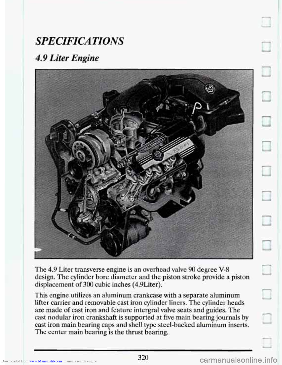
4.9 Liter Engine
The 4.9 Liter transverse engine is an overhead valve 90 degree V-8
design. The cylinder bore diameter and the piston stroke provide a piston
displacement of
300 cubic inches (4.9Liter).
This engine utilizes an aluminum crankcase with a separate aluminum
lifter carrier and removable cast iron cylinder liners. The cylinder heads
ar,e made
of cast iron and feature intergral valve seats and guides. The
cast nodular iron crankshaft is supported at five main bearing journals by
cast iron main bearing caps and shell type steel-backed aluminum inserts.
The center main bearing
is the thrust bearing.
B
D
t3
320
Page 334 of 399

Downloaded from www.Manualslib.com manuals search engine The cast aluminum pistons use two compression rings and one oil control
ring. The pistons are tin plated to provide a non-scuffing surface when
the engine is new.
c_ A steel camshaft is supported by five steel backed babbit bearings. It is
driven by the crankshaft through a chain at
the front of the engine. The
give gear is keyed to the crankshaft and the driven sprocket is bolted to
the camshaft. Both the crankshaft gear and camshaft sprocket have
locating marks to provide the correct valve timing and timing chain
installation.
The valve lifters are roller hydraulic type and are positioned
in the aluminum lifter carrier.
-1_
-
4T60E Transaxle
The Hydra-Matic 4T60E 4-speed overdrive, electronic transaxle consists
primarily of a five element torque converter,
two planetary gear sets,
-- various clutches, final drive assembly, and a control valve body.
321
~. .
Page 335 of 399

Downloaded from www.Manualslib.com manuals search engine c-
The torque converter houses a pump, turbine, pressure plate which is
splined to the turbine, and a stator assembly, serving as a fluid coupling, it
smoothly transmits power from the engine to the transaxle. It also
hydraulically provides a additional torque when required. When applied,
the pressure plate provides a mechanical torque when required. When
applied, the pressure plate provides a mechanical direct drive coupling of
the engine to the transaxle.
-
n
The two planetary gear sets provide the four forward gear ratios and
reverse. Changing of the gear ratios is fully automatic and is
accomplished through the use of various electronic and mechanical
requirements. Four multiple disc clutches, two roller clutches, a sprag
clutch, and three bands provide the friction elements required to obtain
the various ratios with the planetary gear sets.
A hydraulic system (the control valve body) pressurized by a vein type
pump provides the working pressure needed to operate the friction
elements and automatic controls.
Front Suspension
Your fully independent front suspension is a combination strut and spring
design. The frame is isolated from the body with six rubber mounts.
r
Page 336 of 399
Downloaded from www.Manualslib.com manuals search engine Rubber bushings are used at the lower control arm pivots. The upper end
of the strut is isolated by a rubber mount which contains a bearing to
allow for wheel turning. The Speed Sensing Suspension automatically
controls the damping rate
of the struts.
The lower end
of the steering knuckle pivots on a ball joint riveted to the
control arm. The ball joint
is connected ,to the steering knuckle with a
castellated nut and cotter pin.
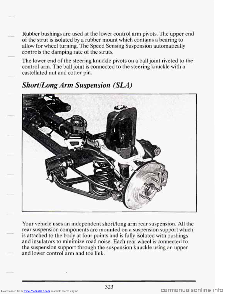
ShortlLong Arm Suspension (SLA)
Your vehicle uses an independent short/long arm rear suspension. All the
rear suspension components are mounted
on a suspension support which
is attached to the body at four points and is
fully isolated with bushings
and insulators to minimize road noise. Each rear wheel is connected to
the suspension support through the suspension knuckle using
an upper
and lower control arm and
toe link. --
Page 337 of 399

Downloaded from www.Manualslib.com manuals search engine The control arms and toe link are attached to the suspension support on
the inboard side, and to a suspension knuckle on the outboard side. The
hub and bearing assembly is mounted to the knuckle and
is a single,
non-serviceable unit which eliminates the need for wheel bearing
adjustment. The load leveling
(ELC) shock absorbers are attached to the
lower control arm, with
the upper end of the shock attached to the
suspension support. The springs are held in position between the lower
control arms and a pocket in the suspension support.
The suspension system also incorporates a
new damping system known as
Speed Sensing Suspension. This system controls the damping forces
in
the shock absorbers and struts, in response to various road and driving
conditions. The systems are capable of making these damping changes
extremely fast.
A computer receives inputs from vertical acceleration sensors, wheel to
body position sensors, vehicle speed sensor,
lift and dive signals. This
computer evaluates the input from these sensors, to control the damping
of each
of the struts and shocks independently to provide varied levels of
suspension control.
The system also has
the capability of providing Speed Sensitive Steering
control. This system changes your steering effort based on your vehicle
speed.
c-
Page 338 of 399
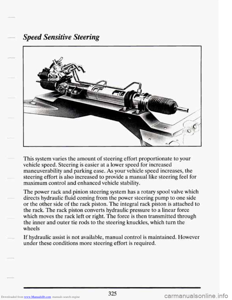
Downloaded from www.Manualslib.com manuals search engine Speed Sensitive Steering
This system varies the amount of steering effort proportionate to your
vehicle speed. Steering is easier at a lower speed for increased
maneuverability and parking ease.
As your vehicle speed increases, the
steering effort is also increased to provide a manual
like steering feel for
maximum control and enhanced vehicle stability.
The power rack and pinion steering system has a rotary spool valve which
directs hydraulic fluid coming from the power steering pump to one side
or the other side
of the rack piston. The integral rack piston is attached to
the rack. The rack piston converts hydraulic pressure to a linear force
which moves the rack left or right. The force is
then transmitted through
the inner and outer tie rods to the steering knuckles, which turn the
wheels
If hydraulic assist is not available, manual control is maintained. However
under these conditions more steering effort
is required.
Page 339 of 399

Downloaded from www.Manualslib.com manuals search engine 4.9 LITER ENGINE
Displacement ............................... 4.9L (300 cu. in.)
No. of Cylinders .............................. 8 - 90 Degree V
Power (Acc. to
SAE 51349) ............... 200 (bhp) @ 4100 rpm
Torque
(Acc. to SAE 51349) ............ 275 (lbs. ft.) @ 3000 rpm
Bore
....................................... 92mm (3.623 in.)
Stroke
..................................... 92mm (3.623 in.)
Compression Ratio
.................................... 9.5:l
Cylinder Block
...... Die Cast Alumbum with Iron Cylinder Bores
Cylinder Heads Cast Iron
Intake Manifold
.............................. Cast Aluminum
Lifter Trpe
................................. Roller Hydraulic
Intake Valve Head Diameter
.................. 45mm (1.772 in.)
Exhaust Valve Head Diameter
................. 38mm (1.496 in.)
Pistons
...................................... Cast Aluminum
Firing Order
.................................. 1-8-4-3-6-5-7-2
Left Bank
.......................................... 1-3-5-7
Right Bank
......................................... 2-4-6-8
Camshaft
............................................. Steel
Camshaft Drive
...................................... Chain
Crankshaft Material
..................... Pearlitic Nodular Iron
Main Bearings
......................................... Five
...................................... 250 (kW) @ 4100 rpm
...................................... 375(N.m) @ 3000 rpm
.. - .- :.,-< ...................................
ENGINE LUBRICATION SYSTEM
Type of Intake ..................................... Stationary
Filter System
...................................... Full-Flow
Oil Pump
........................................... Geroto
326
Page 340 of 399
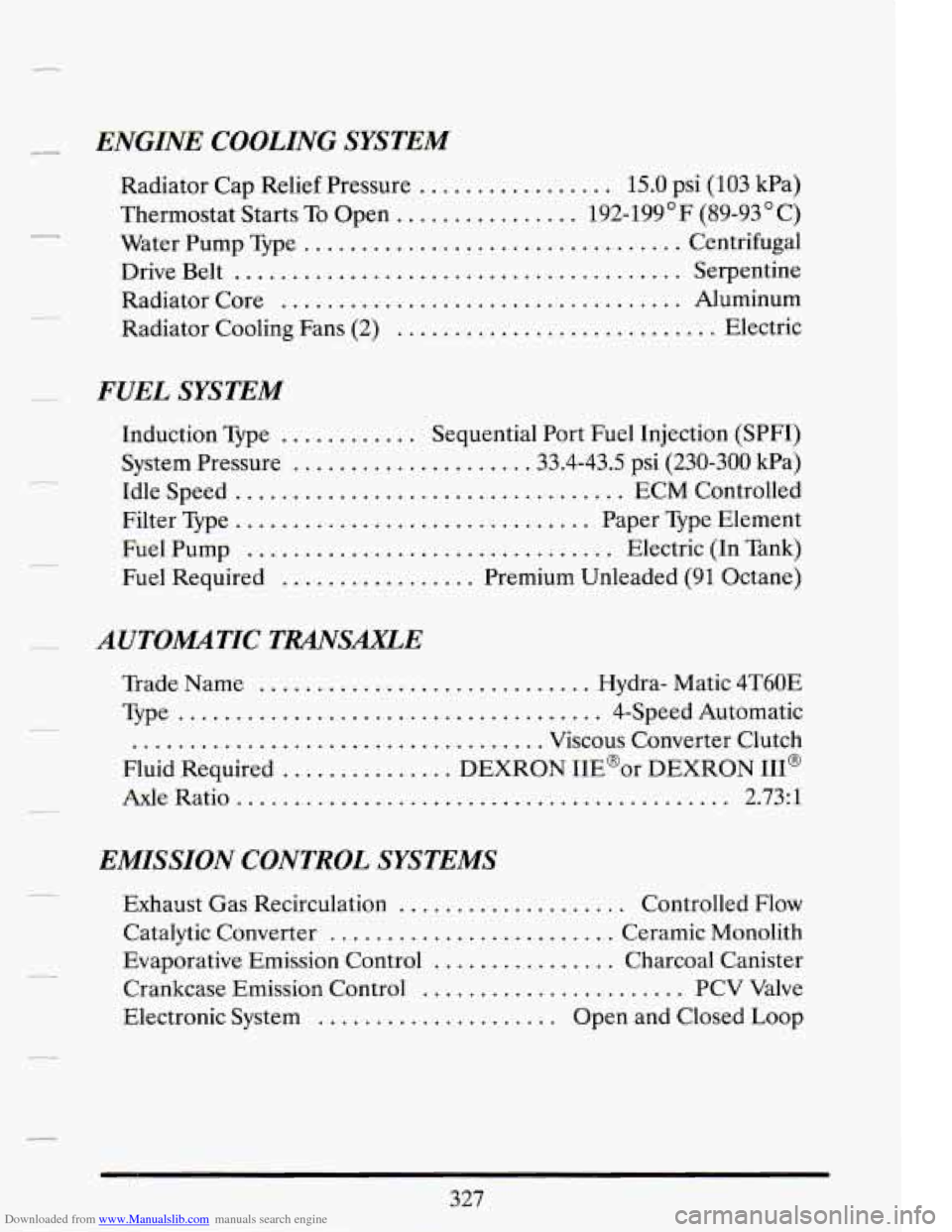
Downloaded from www.Manualslib.com manuals search engine Ly ENGINE COOLING SYSTEM
Radiator Cap Relief Pressure ................. 15.0 psi (103 kPa)
Thermostat Starts To Open
................ 192-199'F (89-93OC)
Water Pump Type
................................. Centrifugal
Drive Belt
....................................... Serpentine
Radiator Core
................................... Aluminum
Radiator Cooling Fans (2)
............................ Electric
FUEL SYSTEM
Induction Type ............ Sequential Port Fuel Injection (SPFI)
System Pressure
.................... .33.4-43.5 psi (230-300 kPa)
Idle Speed
.................................. ECM Controlled
Filter Type
............................... Paper Type Element
Fuel Pump
................................ Electric (In Tank)
Fuel Required ................. Premium Unleaded (91 Octane)
AUTOMATIC TRANSAXLE
Trade Name ............................. Hydra- Matic 4T60E
Type ..................................... 4-Speed Automatic
.................................... Viscous Converter Clutch
Fluid Required
............... DEXRON IIE@or DEXRON HI@
Axle Ratio
........................................... 2.73:l
EMISSION CONTROL SYSTEMS
Exhaust Gas Recirculation .................... Controlled Flow
Catalytic Converter
......................... Ceramic Monolith
Evaporative Emission Control
................ Charcoal Canister
Crankcase Emission Control
....................... PCV Valve
Electronic System
..................... Open and Closed Loop
327
-