CHERY TIGGO 2009 Service Service Manual
Manufacturer: CHERY, Model Year: 2009, Model line: TIGGO, Model: CHERY TIGGO 2009Pages: 1903, PDF Size: 33.38 MB
Page 41 of 1903
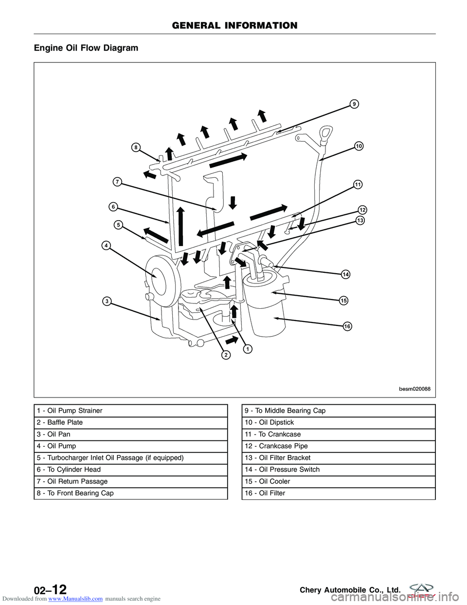
Downloaded from www.Manualslib.com manuals search engine Engine Oil Flow Diagram
1 - Oil Pump Strainer
2 - Baffle Plate
3 - Oil Pan
4 - Oil Pump
5 - Turbocharger Inlet Oil Passage (if equipped)
6 - To Cylinder Head
7 - Oil Return Passage
8 - To Front Bearing Cap9 - To Middle Bearing Cap
10 - Oil Dipstick
11 - To Crankcase
12 - Crankcase Pipe
13 - Oil Filter Bracket
14 - Oil Pressure Switch
15 - Oil Cooler
16 - Oil Filter
GENERAL INFORMATION
BESM020088
02–12Chery Automobile Co., Ltd.
Page 42 of 1903
Downloaded from www.Manualslib.com manuals search engine DIAGNOSIS & TESTING
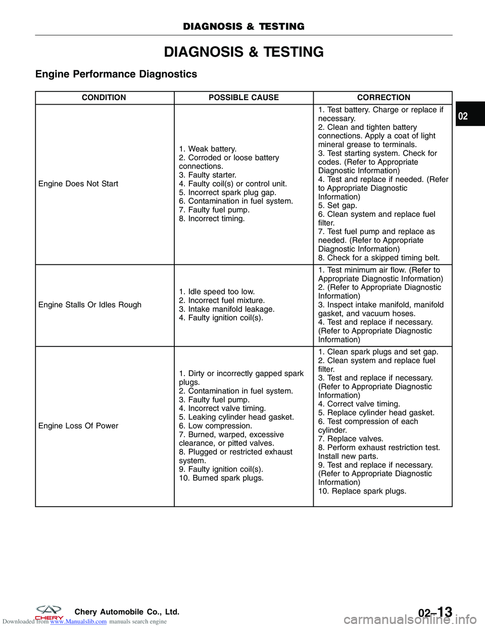
Engine Performance Diagnostics
CONDITIONPOSSIBLE CAUSE CORRECTION
Engine Does Not Start 1. Weak battery.
2. Corroded or loose battery
connections.
3. Faulty starter.
4. Faulty coil(s) or control unit.
5. Incorrect spark plug gap.
6. Contamination in fuel system.
7. Faulty fuel pump.
8. Incorrect timing.1. Test battery. Charge or replace if
necessary.
2. Clean and tighten battery
connections. Apply a coat of light
mineral grease to terminals.
3. Test starting system. Check for
codes. (Refer to Appropriate
Diagnostic Information)
4. Test and replace if needed. (Refer
to Appropriate Diagnostic
Information)
5. Set gap.
6. Clean system and replace fuel
filter.
7. Test fuel pump and replace as
needed. (Refer to Appropriate
Diagnostic Information)
8. Check for a skipped timing belt.
Engine Stalls Or Idles Rough 1. Idle speed too low.
2. Incorrect fuel mixture.
3. Intake manifold leakage.
4. Faulty ignition coil(s).1. Test minimum air flow. (Refer to
Appropriate Diagnostic Information)
2. (Refer to Appropriate Diagnostic
Information)
3. Inspect intake manifold, manifold
gasket, and vacuum hoses.
4. Test and replace if necessary.
(Refer to Appropriate Diagnostic
Information)
Engine Loss Of Power 1. Dirty or incorrectly gapped spark
plugs.
2. Contamination in fuel system.
3. Faulty fuel pump.
4. Incorrect valve timing.
5. Leaking cylinder head gasket.
6. Low compression.
7. Burned, warped, excessive
clearance, or pitted valves.
8. Plugged or restricted exhaust
system.
9. Faulty ignition coil(s).
10. Burned spark plugs.1. Clean spark plugs and set gap.
2. Clean system and replace fuel
filter.
3. Test and replace if necessary.
(Refer to Appropriate Diagnostic
Information)
4. Correct valve timing.
5. Replace cylinder head gasket.
6. Test compression of each
cylinder.
7. Replace valves.
8. Perform exhaust restriction test.
Install new parts.
9. Test and replace if necessary.
(Refer to Appropriate Diagnostic
Information)
10. Replace spark plugs.
DIAGNOSIS & TESTING
02
02–13Chery Automobile Co., Ltd.
Page 43 of 1903
Downloaded from www.Manualslib.com manuals search engine CONDITIONPOSSIBLE CAUSE CORRECTION
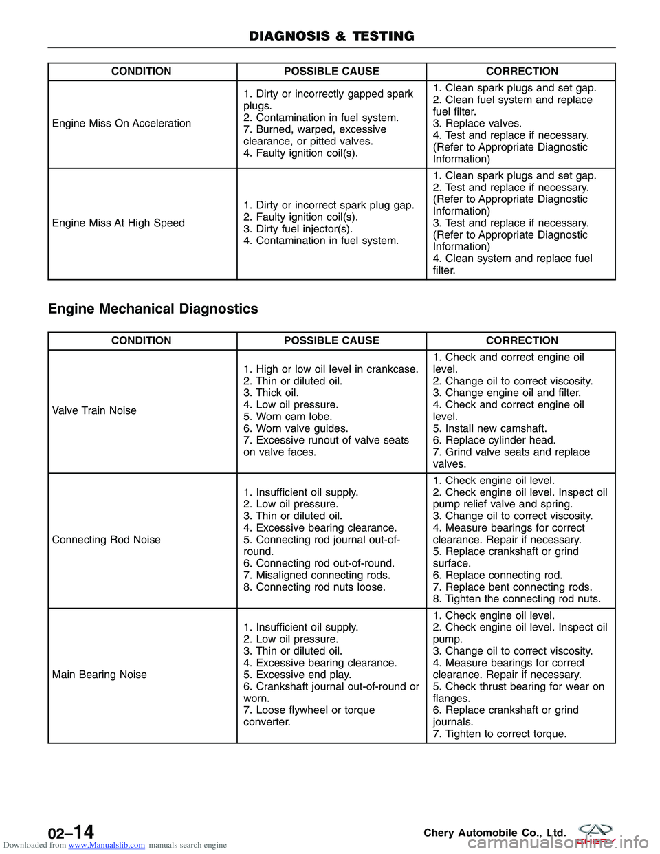
Engine Miss On Acceleration 1. Dirty or incorrectly gapped spark
plugs.
2. Contamination in fuel system.
7. Burned, warped, excessive
clearance, or pitted valves.
4. Faulty ignition coil(s).1. Clean spark plugs and set gap.
2. Clean fuel system and replace
fuel filter.
3. Replace valves.
4. Test and replace if necessary.
(Refer to Appropriate Diagnostic
Information)
Engine Miss At High Speed 1. Dirty or incorrect spark plug gap.
2. Faulty ignition coil(s).
3. Dirty fuel injector(s).
4. Contamination in fuel system.1. Clean spark plugs and set gap.
2. Test and replace if necessary.
(Refer to Appropriate Diagnostic
Information)
3. Test and replace if necessary.
(Refer to Appropriate Diagnostic
Information)
4. Clean system and replace fuel
filter.
Engine Mechanical Diagnostics
CONDITION
POSSIBLE CAUSE CORRECTION
Valve Train Noise 1. High or low oil level in crankcase.
2. Thin or diluted oil.
3. Thick oil.
4. Low oil pressure.
5. Worn cam lobe.
6. Worn valve guides.
7. Excessive runout of valve seats
on valve faces.1. Check and correct engine oil
level.
2. Change oil to correct viscosity.
3. Change engine oil and filter.
4. Check and correct engine oil
level.
5. Install new camshaft.
6. Replace cylinder head.
7. Grind valve seats and replace
valves.
Connecting Rod Noise 1. Insufficient oil supply.
2. Low oil pressure.
3. Thin or diluted oil.
4. Excessive bearing clearance.
5. Connecting rod journal out-of-
round.
6. Connecting rod out-of-round.
7. Misaligned connecting rods.
8. Connecting rod nuts loose.1. Check engine oil level.
2. Check engine oil level. Inspect oil
pump relief valve and spring.
3. Change oil to correct viscosity.
4. Measure bearings for correct
clearance. Repair if necessary.
5. Replace crankshaft or grind
surface.
6. Replace connecting rod.
7. Replace bent connecting rods.
8. Tighten the connecting rod nuts.
Main Bearing Noise 1. Insufficient oil supply.
2. Low oil pressure.
3. Thin or diluted oil.
4. Excessive bearing clearance.
5. Excessive end play.
6. Crankshaft journal out-of-round or
worn.
7. Loose flywheel or torque
converter.1. Check engine oil level.
2. Check engine oil level. Inspect oil
pump.
3. Change oil to correct viscosity.
4. Measure bearings for correct
clearance. Repair if necessary.
5. Check thrust bearing for wear on
flanges.
6. Replace crankshaft or grind
journals.
7. Tighten to correct torque.
DIAGNOSIS & TESTING
02–14Chery Automobile Co., Ltd.
Page 44 of 1903
Downloaded from www.Manualslib.com manuals search engine CONDITIONPOSSIBLE CAUSE CORRECTION
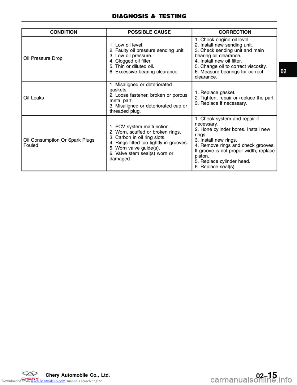
Oil Pressure Drop 1. Low oil level.
2. Faulty oil pressure sending unit.
3. Low oil pressure.
4. Clogged oil filter.
5. Thin or diluted oil.
6. Excessive bearing clearance.1. Check engine oil level.
2. Install new sending unit.
3. Check sending unit and main
bearing oil clearance.
4. Install new oil filter.
5. Change oil to correct viscosity.
6. Measure bearings for correct
clearance.
Oil Leaks 1. Misaligned or deteriorated
gaskets.
2. Loose fastener, broken or porous
metal part.
3. Misaligned or deteriorated cup or
threaded plug.1. Replace gasket.
2. Tighten, repair or replace the part.
3. Replace if necessary.
Oil Consumption Or Spark Plugs
Fouled 1. PCV system malfunction.
2. Worn, scuffed or broken rings.
3. Carbon in oil ring slots.
4. Rings fitted too tightly in grooves.
5. Worn valve guide(s).
6. Valve stem seal(s) worn or
damaged.1. Check system and repair if
necessary.
2. Hone cylinder bores. Install new
rings.
3. Install new rings.
4. Remove rings and check grooves.
If groove is not proper width, replace
piston.
5. Replace cylinder head.
6. Replace seal(s).
DIAGNOSIS & TESTING
02
02–15Chery Automobile Co., Ltd.
Page 45 of 1903
Downloaded from www.Manualslib.com manuals search engine Cylinder Compression Pressure Test
•The result of a cylinder compression pressure test can be utilized to diagnose several engine malfunctions.
• Ensure the battery is completely charged and the engine starter motor is in good operating condition. Otherwise
the indicated compression pressures may not be valid for diagnostic purposes.
� Check engine oil level and add oil if necessary.
� Disconnect the spark plug wires.
� Remove all spark plugs from engine (as spark plugs are being removed, check electrodes for abnormal
firing indicators fouled, hot, oily, etc.).
� Record cylinder number of each spark plug for future reference.
� Disconnect fuel injector electrical connectors.
� Be sure throttle blade is fully open during the compression check.
� Insert compression pressure adaptor or the equivalent into each spark plug hole in cylinder head.
� Crank engine until maximum pressure is reached on gauge. Record each cylinder pressure.
� Compression should not be less than 1000 kPa and not vary more than 25 percent from cylinder to cylinder.
� If one or more cylinders have abnormally low compression pressures, repeat the compression test.
� If the same cylinder or cylinders repeat an abnormally low reading on the second compression test, it could indicate the existence of a problem with the cylinder in question.
NOTE :
The recommended compression pressures are to be used only as a guide to diagnosing engine problems. An engine
should not be disassembled to determine the cause of low compression unless some malfunction is present.
Cylinder Head Gasket Test
• A cylinder head gasket leak can be located between adjacent cylinders, between a cylinder and the adjacent
water jacket or from an oil passage to the exterior of the engine.
• Possible indications of the cylinder head gasket leaking between adjacent cylinders are:
� Loss of engine power
� Engine misfiring
� Poor fuel economy
• Possible indications of the cylinder head gasket leaking between a cylinder and an adjacent water jacket are:
� Engine overheating
� Loss of coolant
� Excessive steam (white smoke) emitting from exhaust
� Coolant foaming
DIAGNOSIS & TESTING
02–16Chery Automobile Co., Ltd.
Page 46 of 1903
Downloaded from www.Manualslib.com manuals search engine ON-VEHICLE SERVICE
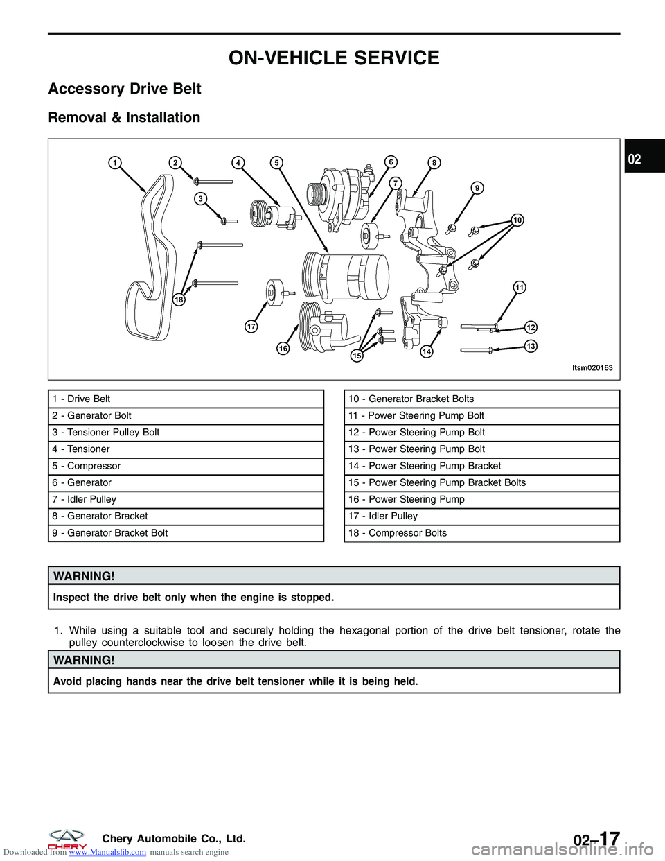
Accessory Drive Belt
Removal & Installation
WARNING!
Inspect the drive belt only when the engine is stopped.
1. While using a suitable tool and securely holding the hexagonal portion of the drive belt tensioner, rotate thepulley counterclockwise to loosen the drive belt.
WARNING!
Avoid placing hands near the drive belt tensioner while it is being held.
1 - Drive Belt
2 - Generator Bolt
3 - Tensioner Pulley Bolt
4 - Tensioner
5 - Compressor
6 - Generator
7 - Idler Pulley
8 - Generator Bracket
9 - Generator Bracket Bolt10 - Generator Bracket Bolts
11 - Power Steering Pump Bolt
12 - Power Steering Pump Bolt
13 - Power Steering Pump Bolt
14 - Power Steering Pump Bracket
15 - Power Steering Pump Bracket Bolts
16 - Power Steering Pump
17 - Idler Pulley
18 - Compressor Bolts
LTSM020163
02
02–17Chery Automobile Co., Ltd.
Page 47 of 1903
Downloaded from www.Manualslib.com manuals search engine 2. Remove the drive belt.
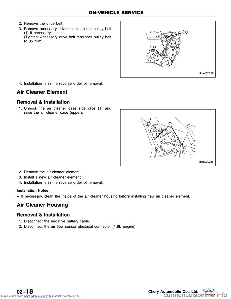
3. Remove accessory drive belt tensioner pulley bolt(1) if necessary.
(Tighten: Accessory drive belt tensioner pulley bolt
to 35 N·m)
4. Installation is in the reverse order of removal.
Air Cleaner Element
Removal & Installation
1. Unhook the air cleaner case side clips (1) and raise the air cleaner case (upper).
2. Remove the air cleaner element.
3. Install a new air cleaner element.
4. Installation is in the reverse order of removal.
Installation Notes:
• If necessary, clean the inside of the air cleaner housing before installing new air cleaner element.
Air Cleaner Housing
Removal & Installation
1. Disconnect the negative battery cable.
2. Disconnect the air flow sensor electrical connector (1.8L Engine).
ON-VEHICLE SERVICE
LTSM020196
LTSM020238
02–18Chery Automobile Co., Ltd.
Page 48 of 1903
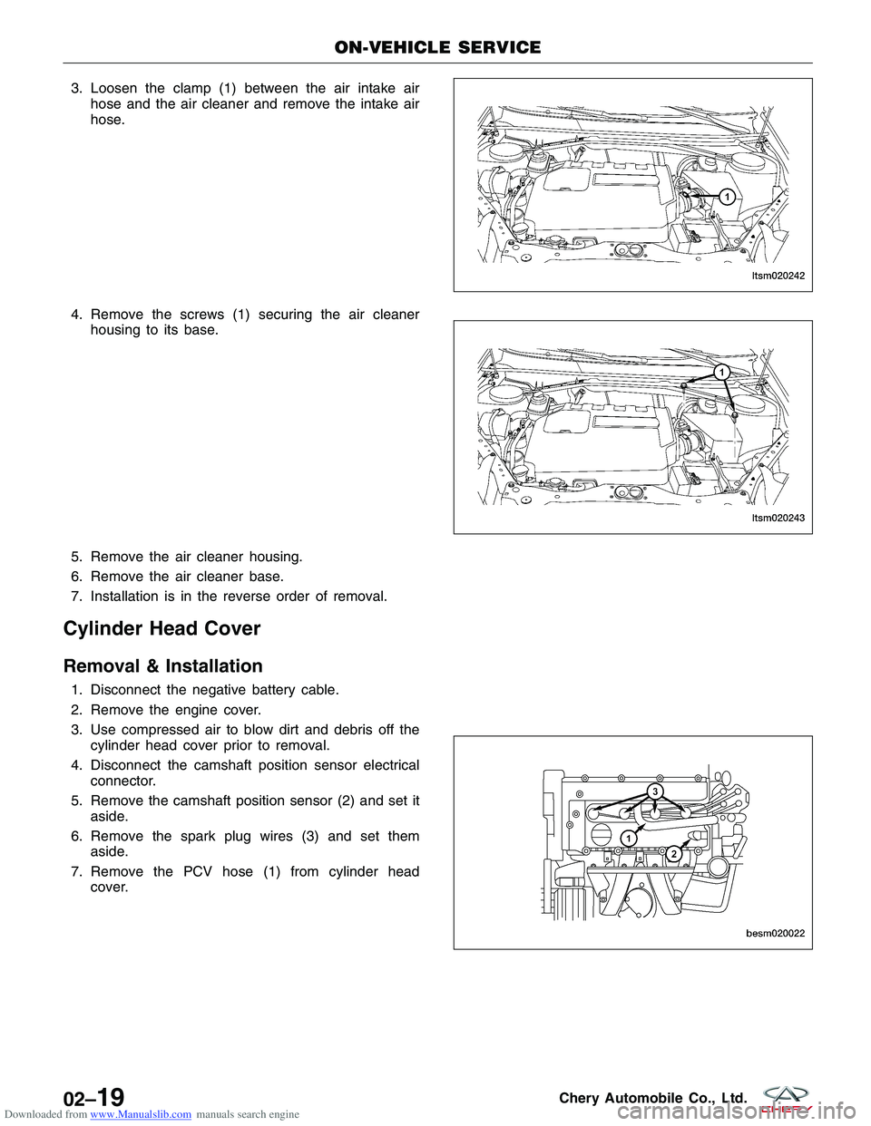
Downloaded from www.Manualslib.com manuals search engine 3. Loosen the clamp (1) between the air intake airhose and the air cleaner and remove the intake air
hose.
4. Remove the screws (1) securing the air cleaner housing to its base.
5. Remove the air cleaner housing.
6. Remove the air cleaner base.
7. Installation is in the reverse order of removal.
Cylinder Head Cover
Removal & Installation
1. Disconnect the negative battery cable.
2. Remove the engine cover.
3. Use compressed air to blow dirt and debris off the cylinder head cover prior to removal.
4. Disconnect the camshaft position sensor electrical connector.
5. Remove the camshaft position sensor (2) and set it aside.
6. Remove the spark plug wires (3) and set them aside.
7. Remove the PCV hose (1) from cylinder head cover.
ON-VEHICLE SERVICE
LTSM020242
LTSM020243
BESM020022
02–19Chery Automobile Co., Ltd.
Page 49 of 1903
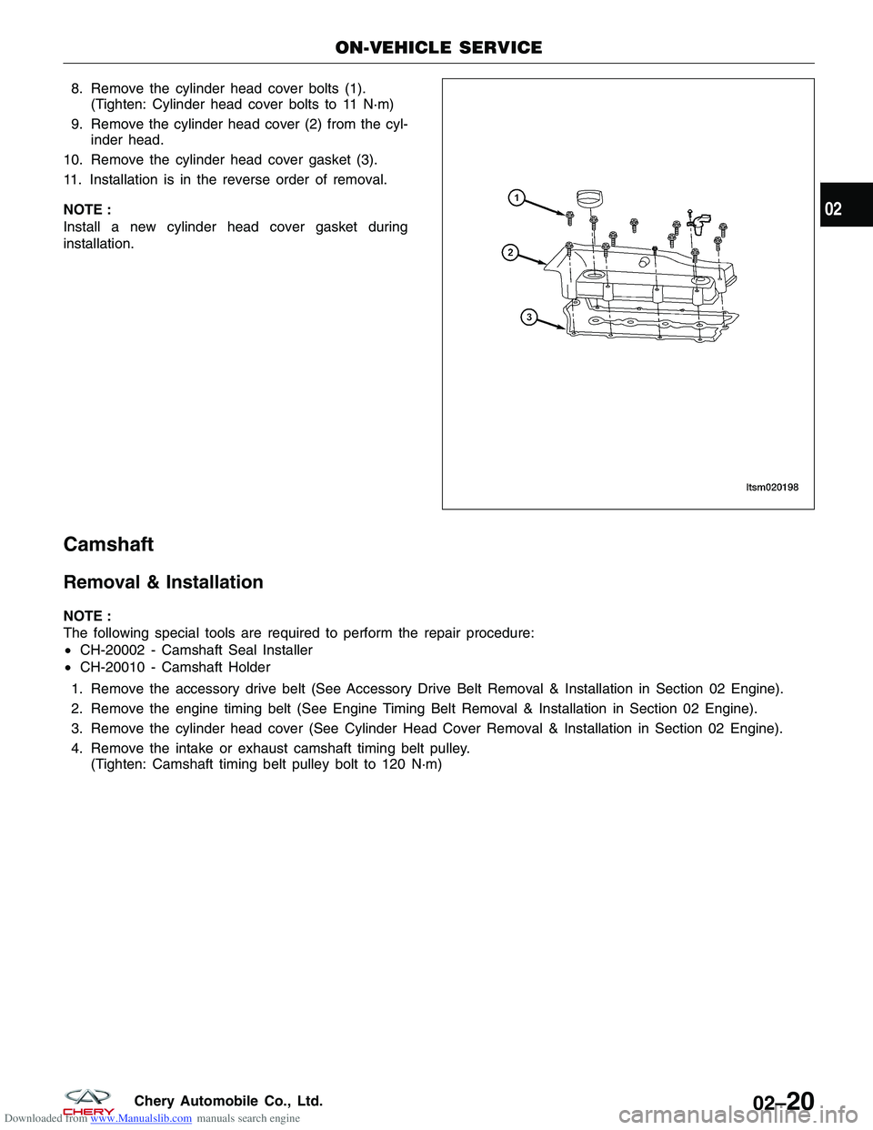
Downloaded from www.Manualslib.com manuals search engine 8. Remove the cylinder head cover bolts (1).(Tighten: Cylinder head cover bolts to 11 N·m)
9. Remove the cylinder head cover (2) from the cyl- inder head.
10. Remove the cylinder head cover gasket (3).
11. Installation is in the reverse order of removal.
NOTE :
Install a new cylinder head cover gasket during
installation.
Camshaft
Removal & Installation
NOTE :
The following special tools are required to perform the repair procedure:
• CH-20002 - Camshaft Seal Installer
• CH-20010 - Camshaft Holder
1. Remove the accessory drive belt (See Accessory Drive Belt Removal & Installation in Section 02 Engine).
2. Remove the engine timing belt (See Engine Timing Belt Removal & Installation in Section 02 Engine).
3. Remove the cylinder head cover (See Cylinder Head Cover Removal & Installation in Section 02 Engine).
4. Remove the intake or exhaust camshaft timing belt pulley. (Tighten: Camshaft timing belt pulley bolt to 120 N·m)
ON-VEHICLE SERVICE
LTSM020198
02
02–20Chery Automobile Co., Ltd.
Page 50 of 1903
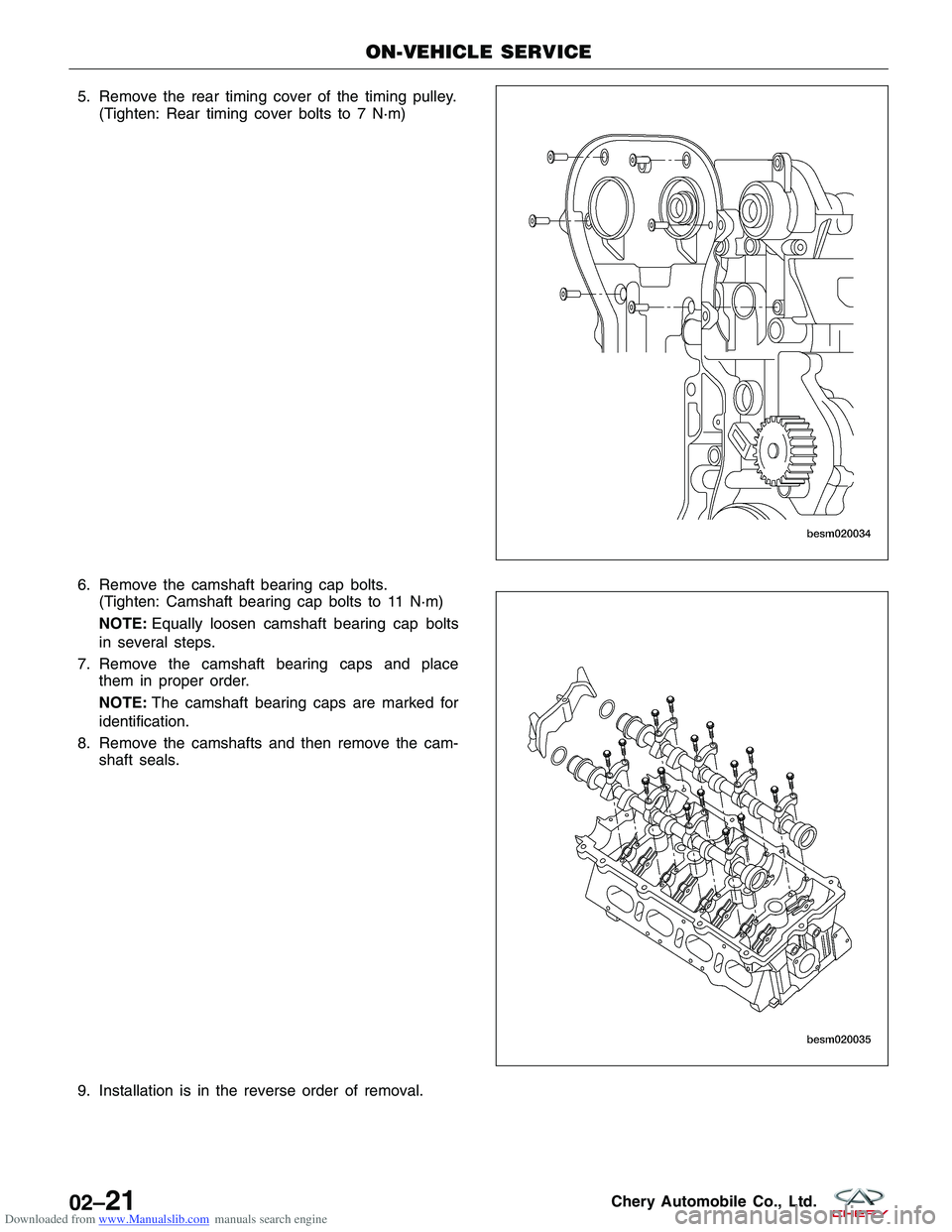
Downloaded from www.Manualslib.com manuals search engine 5. Remove the rear timing cover of the timing pulley.(Tighten: Rear timing cover bolts to 7 N·m)
6. Remove the camshaft bearing cap bolts. (Tighten: Camshaft bearing cap bolts to 11 N·m)
NOTE: Equally loosen camshaft bearing cap bolts
in several steps.
7. Remove the camshaft bearing caps and place them in proper order.
NOTE: The camshaft bearing caps are marked for
identification.
8. Remove the camshafts and then remove the cam- shaft seals.
9. Installation is in the reverse order of removal.
ON-VEHICLE SERVICE
BESM020034
BESM020035
02–21Chery Automobile Co., Ltd.