CHEVROLET ASTRO CARGO VAN 1995 2.G Owners Manual
Manufacturer: CHEVROLET, Model Year: 1995, Model line: ASTRO CARGO VAN, Model: CHEVROLET ASTRO CARGO VAN 1995 2.GPages: 342, PDF Size: 17.57 MB
Page 111 of 342
Downloaded from www.Manualslib.com manuals search engine For more details about DRL, see “Headlamps and Vehicle Lighting” in this
section.
The
DRL indicator light is on whenever the ignition and the headlight
switch and parking brake are
off. For more details about DRL, see “Lights”
in this part.
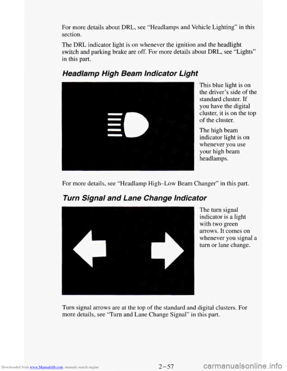
Headlamp High Beam Indicator Light
This blue light is on
the driver’s side
of the
standard cluster.
If
you have the digital
cluster, it
is on the top
of the cluster.
The high beam
indicator light is
on
whenever you use
your high beam
headlamps.
For more details, see “Headlamp High-Low Beam Changer” in this part.
Turn Signal and Lane Change Indicator
The turn signal
indicator is
a light
with two green
arrows. It comes on
whenever you signal
a
turn or lane change.
Turn signal arrows are at the
top of the standard and digital clusters. For
more details, see “Turn and Lane Change Signal”
in this part.
2-57
Page 112 of 342
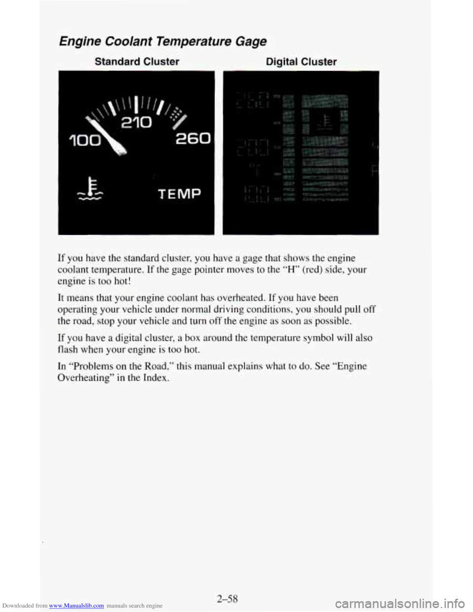
Downloaded from www.Manualslib.com manuals search engine Englne Coolant Temperature Gage
Standard Cluster Digital Cluster
If you have the standard cluster, you have a gage that shows the engine
coolant temperature. If the gage pointer moves to the
“H” (red) side, your
engine is
too hot!
It means that your engine coolant has overheated. If you have been
operating your vehicle under normal driving conditions, you should pull off
the road, stop your vehicle and turn
off the engine as soon as possible.
If you have
a digital cluster, a box around the temperature symbol will also
flash when your engine is too hot.
In “Problems on
the Road,” this manual explains what to do. See “Engine
Overheating”
in the Index.
2-5 8
Page 113 of 342
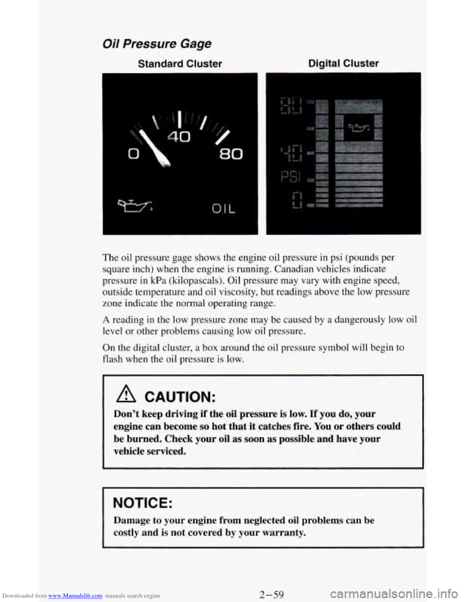
Downloaded from www.Manualslib.com manuals search engine Oil Pressure Gage
Standard Cluster Digital Cluster
The
oil pressure gage shows the engine oil pressure in psi (pounds per
square inch) when the engine is running. Canadian vehicles indicate
pressure in kPa (kilopascals). Oil pressure may vary with engine speed,
outside temperature and oil viscosity, but readings above the low pressure
zone indicate the normal operating range.
A reading in the low pressure zone may be caused by a dangerously low oil
level or other problems causing low
oil pressure.
On the digital cluster, a box around the oil pressure symbol will begin to
flash when the oil pressure
is low.
A CAUTION:
Don’t keep driving if the oil pressure is low. If you do, your
engine can become
so hot that it catches fire. You or others could
be burned. Check your oil
as soon as possible and have your
vehicle serviced.
NOTICE:
Damage to your engine from neglected oil problems can be
costly and
is not covered by your warranty.
2-59
Page 114 of 342
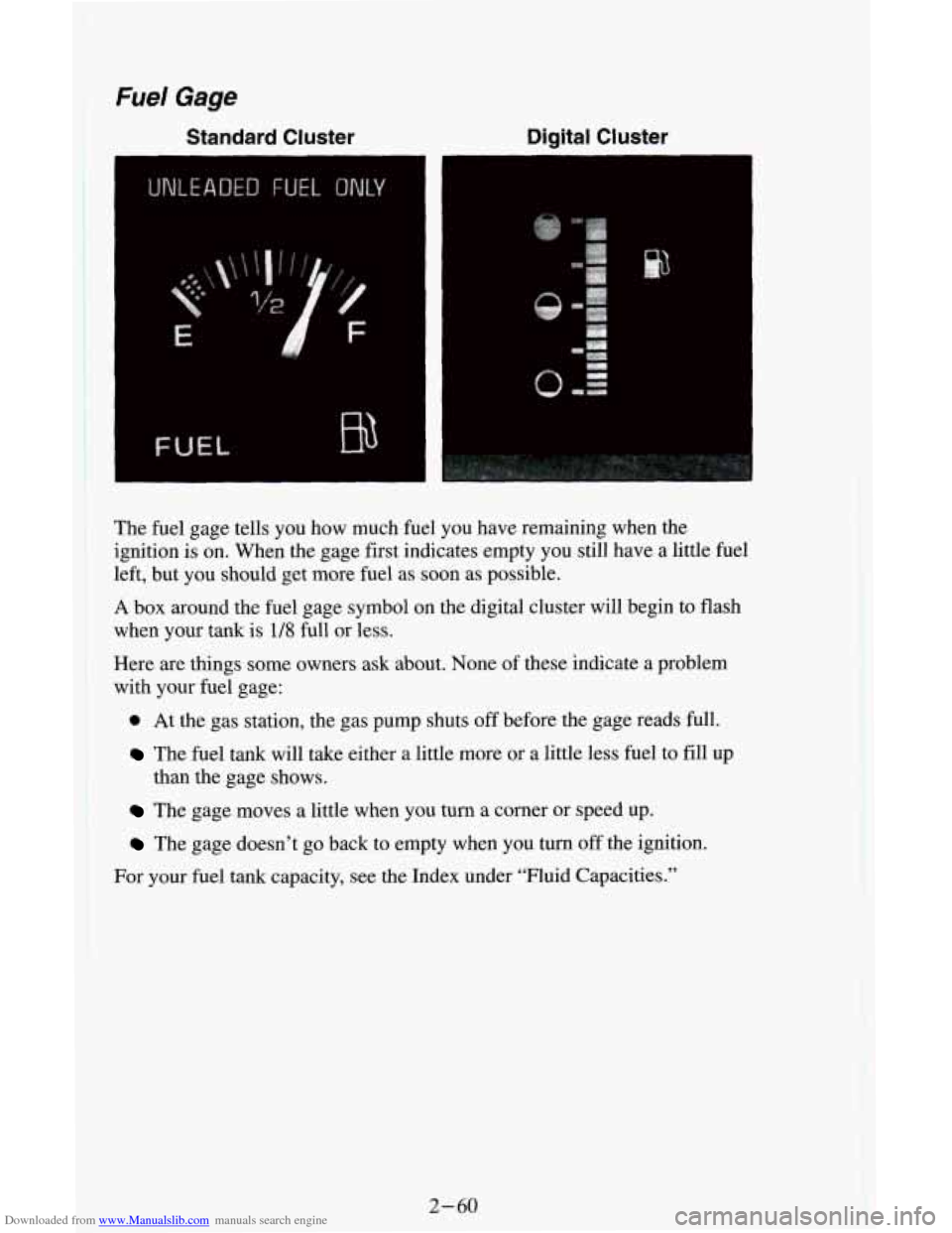
Downloaded from www.Manualslib.com manuals search engine The fuel gage tells you how much fuel you have remaining when the
ignition is on. When the gage first indicates empty you still have a little fuel
left, but you should get more fuel as soon as possible.
A box around the fuel gage symbol on the digital cluster will begin to flash
when
your tank is 1/8 full or less.
Here are things some owners ask about. None
of these indicate a problem
with your fuel gage:
0 At the gas station, the gas pump shuts off before the gage reads full.
The fuel tank will take either a little more or a little less fuel to fill up
The gage moves a little when you turn a comer or speed up.
The gage doesn’t go back to empty when you tum off the ignition.
than
the gage shows.
I
For your fuel tank capacity, see the Index under “Fluid Capacities.”
2-60
Page 115 of 342
Downloaded from www.Manualslib.com manuals search engine Voltmeter
Standard Cluster Digital
Cluster
VOLTS
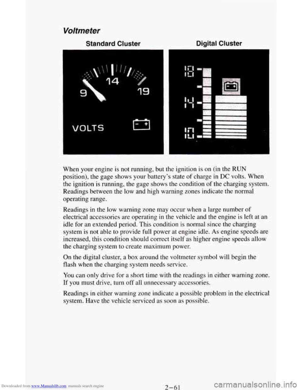
When your engine is not running, but the ignition is on (in the RUN
position), the gage shows your battery's state of charge in DC volts. When
the ignition
is running, the gage shows the condition of the charging system.
Readings between the low and high warning zones indicate the normal
operating range.
Readings in the low warning zone may occur when a large number of
electrical accessories are operating
in the vehicle and the engine is left at an
idle for an extended period. This condition
is normal since the charging
system is
not able to provide full power at engine idle. As engine speeds are
increased, this condition should correct itself as higher engine speeds allow
the charging system to create maximum power.
On the digital cluster, a box around the voltmeter symbol will begin the
flash when the charging system needs service.
You can only drive for a short time with the readings
in either warning zone.
If
you must drive, turn off all unnecessary accessories.
Readings in either warning zone indicate a possible problem in the electrical
system. Have the vehicle serviced as soon as possible.
2- 61
Page 116 of 342
Downloaded from www.Manualslib.com manuals search engine Luggage Carrier (Option)
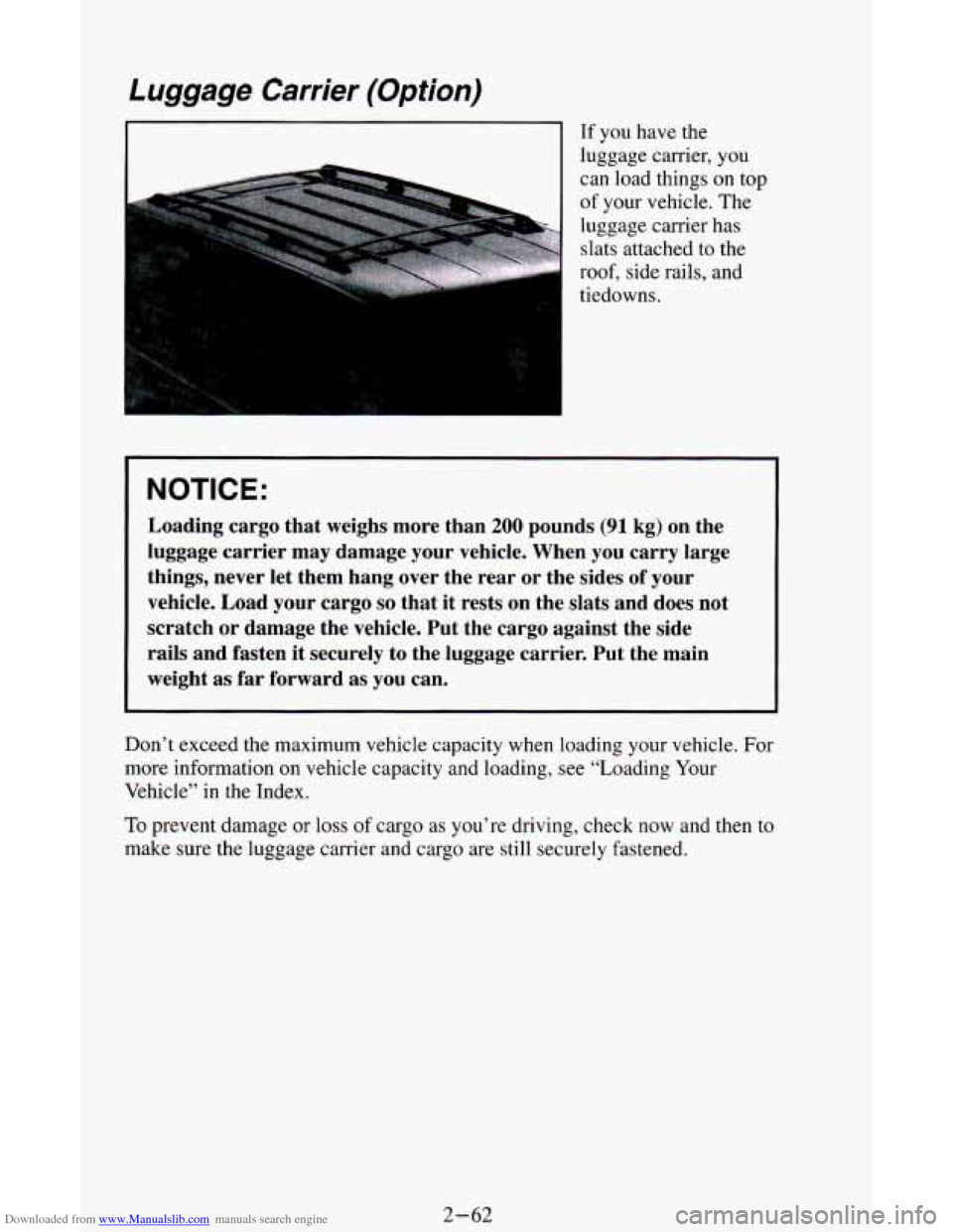
I If you have the
luggage carrier, you
can load things
on top
of your vehicle. The
luggage carrier has
slats attached to the
roof, side rails, and
tiedowns.
NOTICE:
Loading cargo that weighs more than 200 pounds (91 kg) on the
luggage carrier may damage your vehicle. When you carry large
things, never let them hang over the rear or the sides of your
vehicle. Load your cargo
so that it rests on the slats and does not
scratch or damage the vehicle. Put the cargo against the side
rails and fasten it securely to the luggage carrier. Put the main
weight as far forward as you can.
Don’t exceed the maximum vehicle capacity when loading your vehicle. For
more information
on vehicle capacity and loading, see “Loading Your
Vehicle” in the Index.
To prevent damage or loss of cargo as you’re driving, check now and then to
make sure the luggage carrier and cargo are still securely fastened.
2-62
Page 117 of 342
Downloaded from www.Manualslib.com manuals search engine Trailer Wiring Harness
If you have the optional trailering package, your vehicle will have an 8-wire
harness, consisting of a 7-wire harness and one
CHMSL battery feed wire.
The harness is stored
on the passenger side of the van near the rear wheel
well. This harness has a
30 amp battery feed wire and no connector, and
should
be wired by a qualified service person. Attach the harness to the
trailer, then tape or strap it
to your vehicle’s frame rail. Be sure you leave it
loose enough
so the wiring doesn’t bend or break, but not so loose that it
drags
on the ground.
The harness must be routed out of your vehicle between the rear door and
the floor, with enough of the harness left on both sides
so that the trailer or
the body won’t pull it.
Store the harness in its original place. Wrap the harness together and tie it
neatly
so it won’t be damaged.
2-63
Page 118 of 342

Downloaded from www.Manualslib.com manuals search engine Notes
2-64
Page 119 of 342
Downloaded from www.Manualslib.com manuals search engine Comfort Controls & Audio Systems
Section
In this section you’ll find out how to operate the comfort control systems
and audio systems offered with your vehicle. Be sure
to read about the
particular system supplied with your vehicle.
Comfort Controls
Heater Controls
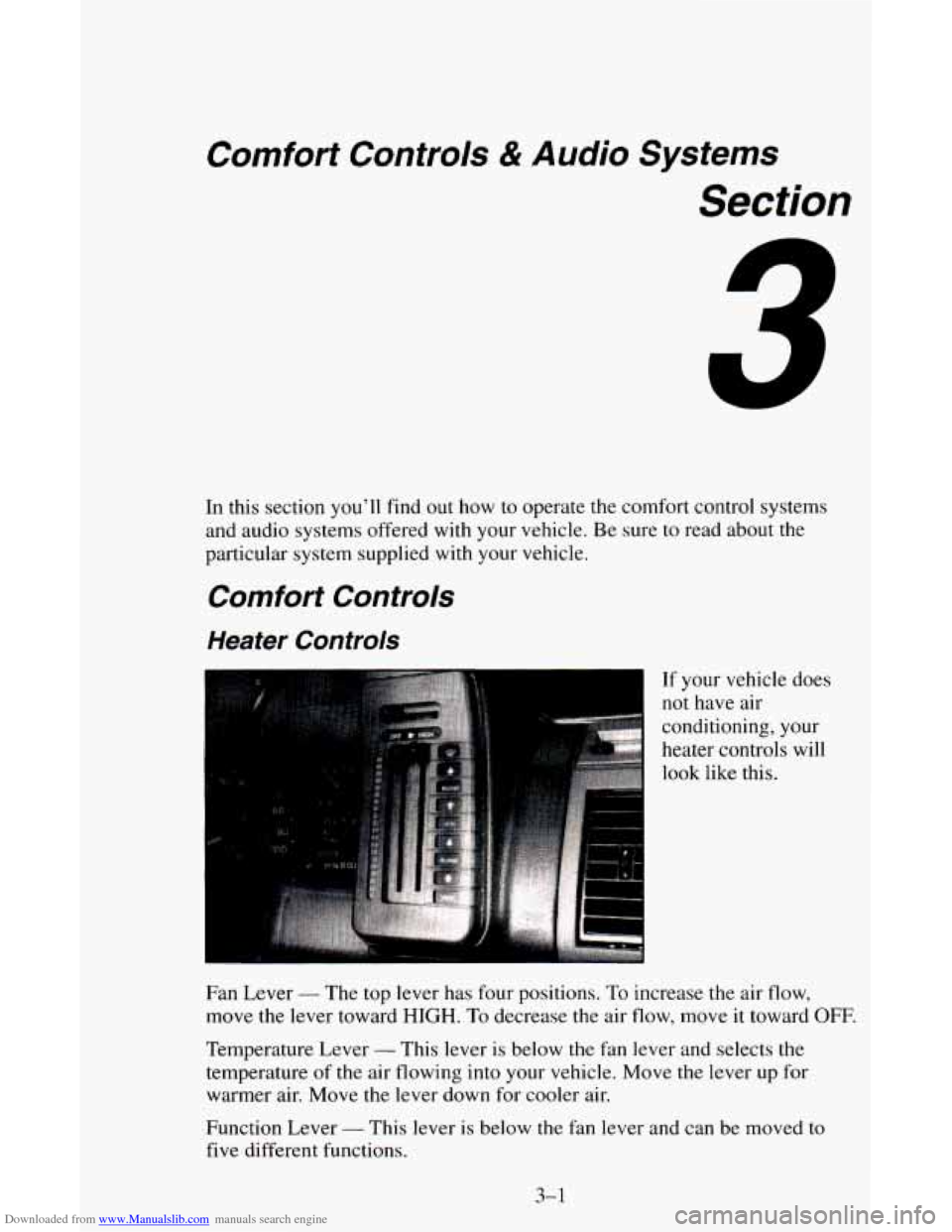
If your vehicle does
not have air
conditioning, your
heater controls will
look like this.
Fan Lever
- The top lever has four positions. To increase the air flow,
move the lever toward
HIGH. To decrease the air flow, move it toward OFF.
Temperature Lever - This lever is below the fan lever and selects the
temperature
of the air flowing into your vehicle. Move the lever up for
warmer air. Move the lever down for cooler air.
Function Lever
- This lever is below the fan lever and can be moved to
five different functions.
3-1
Page 120 of 342
Downloaded from www.Manualslib.com manuals search engine DEFROST-The setting with the defrost symbol operates the defroster. Most
of the air comes out near the windshield, with some going to the floor vents and
front side windows. Use
this when you get fog or ice on the windshield.
HTR (Heater) - Most of the air comes out near the floor. The rest comes
out from the defroster
vents under the windshield and at the front side
windows. This is best for cold weather.
VENT
- The air comes out at the vents on your instrument panel.
BLEND (Position
1) - With this setting, the heated outside air comes out
both
the heater vents and defroster vents. The lever can be positioned
anywhere between to adjust the proportion of air coming through each
vent.
Adjust the temperature lever for warmer or cooler air.
BLEND (Position
2) - With this setting, the heated outside air comes out
both the instrument panel vents and heater vents. The lever can be
positioned anywhere between
to adjust the proportion of air coming through
each
vent. Adjust the temperature lever for warmer or cooler air.
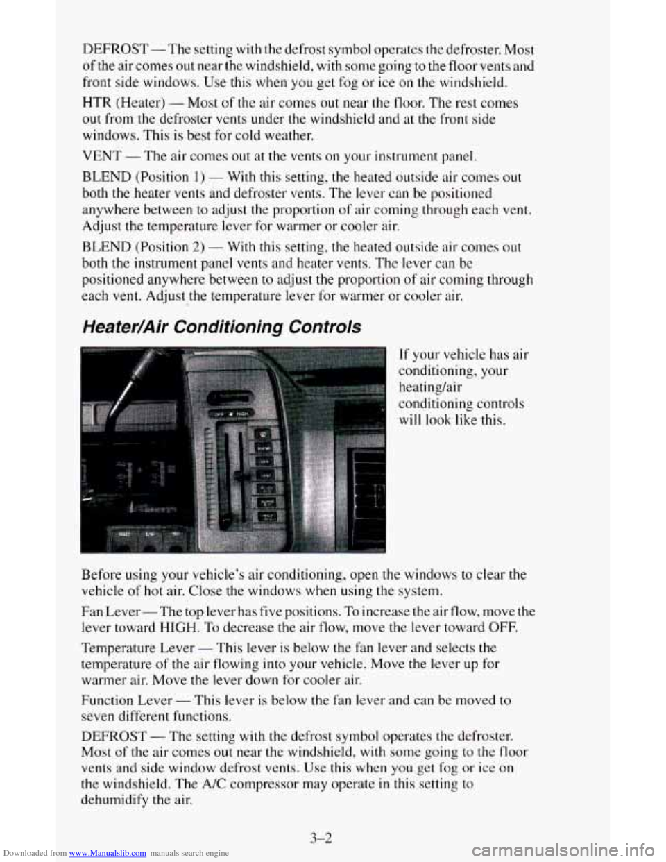
Heater/Air Conditioning Controls
If your vehicle has air
conditioning, your
heatinghir
conditioning controls
will
look like this.
Before using your vehicle’s air conditioning, open the windows to clear the
vehicle
of hot air. Close the windows when using the system.
Fan Lever- The top lever has five positions.
To increase the air flow, move the
lever toward
HIGH. To decrease the air flow, move the lever toward OFF.
Temperature Lever
- This lever is below the fan lever and selects the
temperature of the air flowing into your vehicle. Move the lever up for
warmer air. Move the lever down for cooler air.
Function Lever
- This lever is below the fan lever and can be moved to
seven different functions.
DEFROST
- The setting with the defrost symbol operates the defroster.
Most of the air comes out near the windshield,
with some going to the floor
vents and side window defrost vents. Use this when you get fog or ice on
the windshield. The A/C compressor may operate in this setting to
dehumidify the air.
3-2