CHEVROLET CAMARO 1967 1.G Chassis Workshop Manual
Manufacturer: CHEVROLET, Model Year: 1967, Model line: CAMARO, Model: CHEVROLET CAMARO 1967 1.GPages: 659, PDF Size: 114.24 MB
Page 231 of 659
REAR SUSPENSION AND DRIVE LINE 4-41
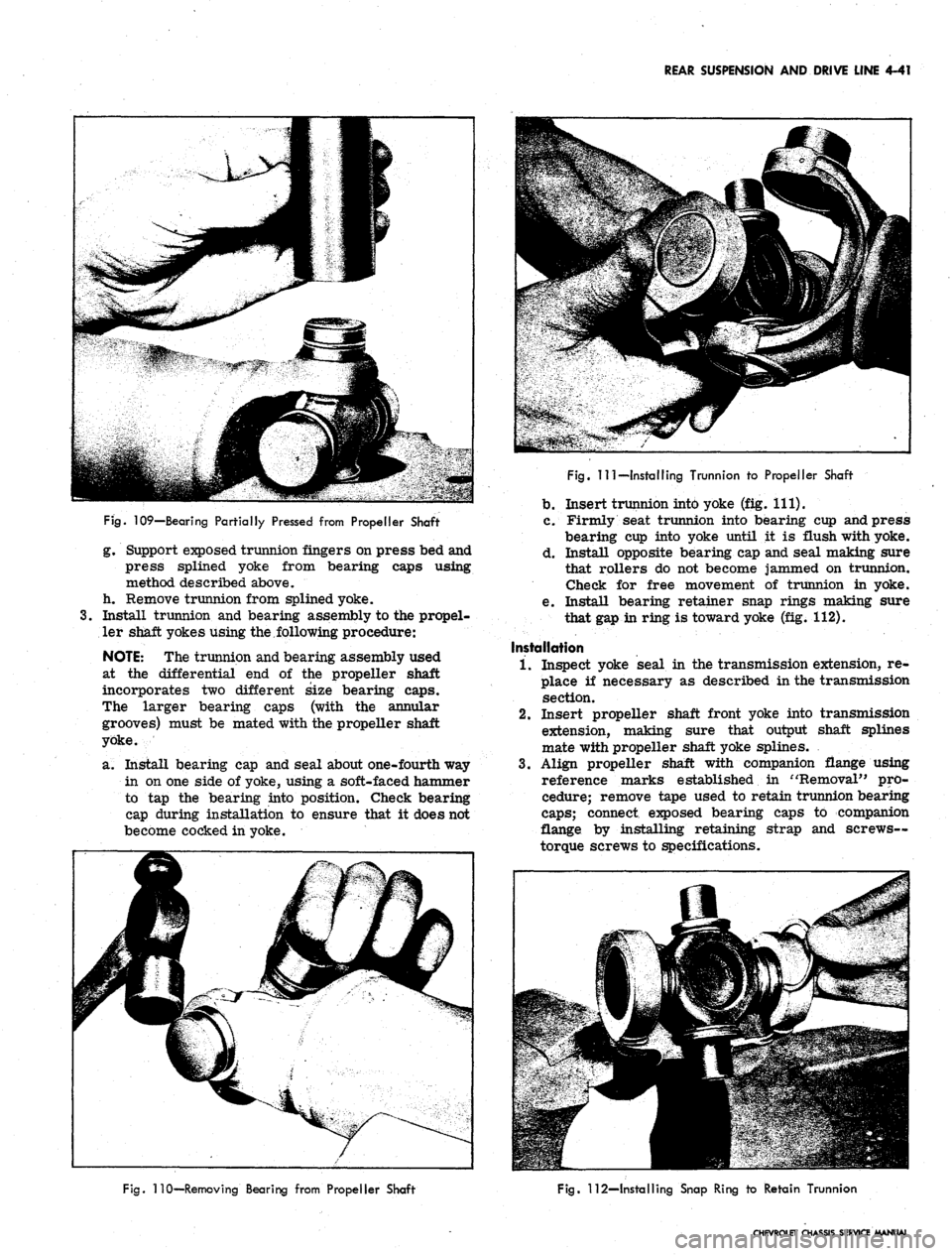
Fig.
109—Bearing Partially Pressed from Propeller Shaft
g. Support exposed trunnion fingers on press bed and
press splined yoke from bearing caps using
method described above,
h. Remove trunnion from splined yoke.
3.
Install trunnion and bearing assembly to the propel-
ler shaft yokes using the,following procedure:
NOTE:
The trunnion and bearing assembly used
at the differential end of the propeller shaft
incorporates two different size bearing caps.
The larger bearing caps (with the annular
grooves) must be mated with the propeller shaft
yoke.
a. Install bearing cap and seal about one-fourth way
in on one side of yoke, using a soft-faced hammer
to tap the bearing into position. Check bearing
cap during installation to ensure that it does not
become cocked in yoke.
Fig.
Ill—Installing Trunnion to Propeller Shaft
b.
Insert trunnion into yoke (fig. 111).
c. Firmly seat trunnion into bearing cup and press
bearing cup into yoke until it is flush with yoke.
d. Install opposite bearing cap and seal making sure
that rollers do not become jammed on trunnion.
Check for free movement of trunnion in yoke.
e. Install bearing retainer snap rings making sure
that gap in ring is toward yoke (fig. 112).
Installation
1.
Inspect yoke seal in the transmission extension, re-
place if necessary as described in the transmission
section.
2.
Insert propeller shaft front yoke into transmission
extension, making sure that output shaft splines
mate with propeller shaft yoke splines.
3.
Align propeller shaft with companion flange using
reference marks established in "Removal" pro-
cedure; remove tape used to retain trunnion bearing
caps;
connect exposed bearing caps to companion
flange by installing retaining strap and screws—
torque screws to specifications.
Fig.
110—Removing Bearing from Propeller Shaft
Fig.
112—Installing Snap Ring to Retain Trunnion
CHEVROLET CHASSIS SERVICE MANUAL
Page 232 of 659
REAR SUSPENSION AND DRIVE LINE 4-42
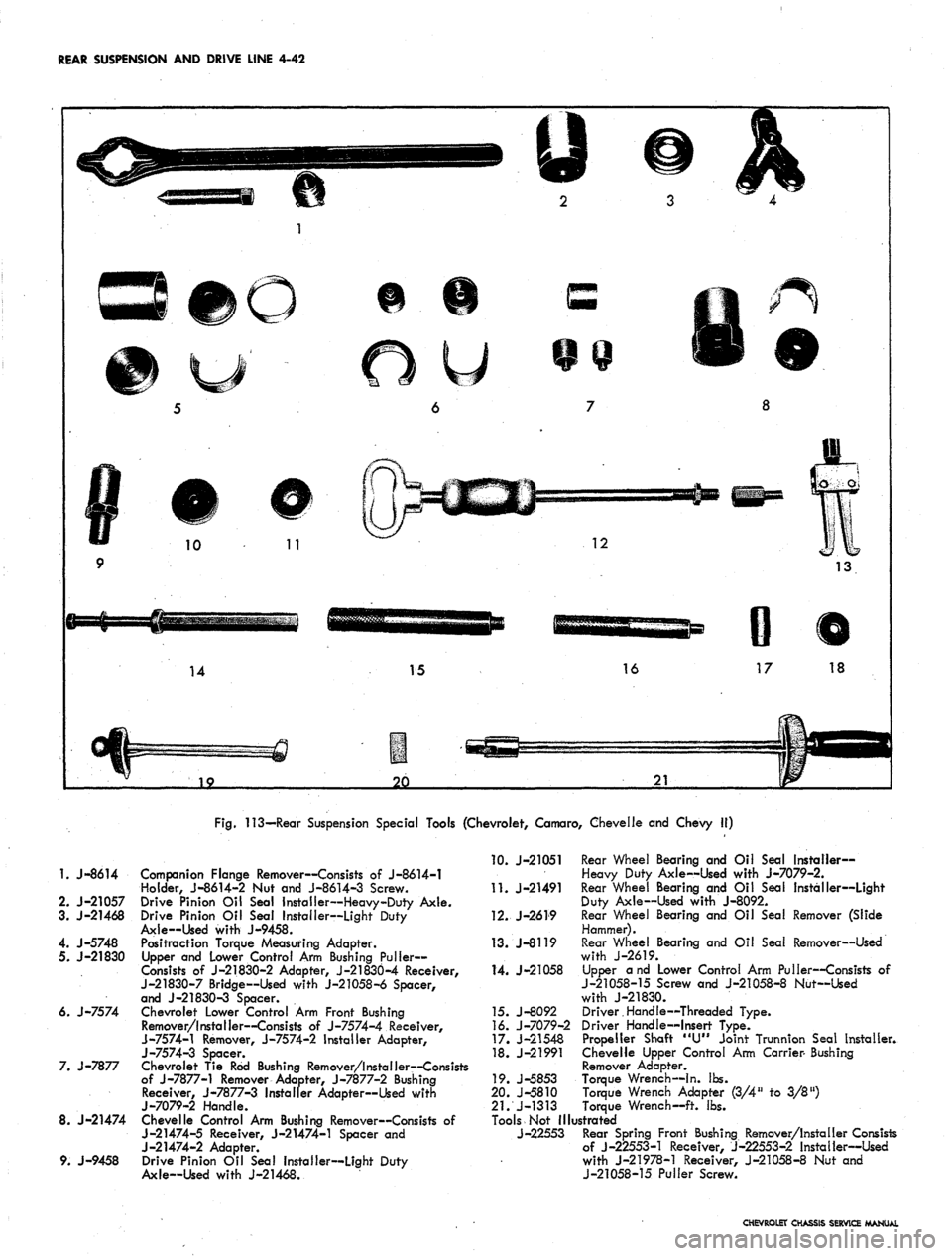
Fig.
113—Rear Suspension Special Tools (Chevrolet, Camaro, Chevelle and Chevy II)
1.
J-8614
2.
J-21057
3. J-21468
4. J-5748
5. J-21830
6. J-7574
7. J-7877
8. J-21474
9. J-9458
Companion Flange Remover—Consists of J-8614-1
Holder, J-8614-2 Nut and J-8614-3 Screw.
Drive Pinion Oil Seal Installer—Heavy-Duty Axle.
Drive Pinion Oil Seal Installer—Light Duty
Axle—Used with J-9458.
Positraction Torque Measuring Adapter.
Upper and Lower Control Arm Bushing Puller-
Consists of J-21830-2 Adapter, J-21830-4 Receiver,
J-21830-7 Bridge—Used with J-21058-6 Spacer,
and J-21830-3 Spacer.
Chevrolet Lower Control Arm Front Bushing
Remover/Installer—Consists of J-7574-4 Receiver,
J-7574-1 Remover, J-7574-2 Installer Adapter,
J-7574-3 Spacer.
Chevrolet Tie Rod Bushing Remover/Installer—Consists
of J-7877-1 Remover Adapter, J-7877-2 Bushing
Receiver, J-7877-3 Installer Adapter—Used with
j-7079-2
Handle.
Chevelle Control Arm Bushing Remover—Consists of
J-21474-5 Receiver, J-21474-1 Spacer and
J-21474-2 Adapter.
Drive Pinion Oil Seal Installer—Light Duty
Axle—Used with J-21468.
10.
J-21051 Rear Wheel Bearing and Oil Seal Installer-
Heavy Duty Axle—Used with J-7079-2.
11.
J-21491 Rear Wheel Bearing and Oil Seal Installer—Light
Duty Axle—Used with J-8092.
12.
J-2619 Rear Wheel Bearing and Oil Seal Remover (Slide
Hammer).
13.
J-8119 Rear Wheel Bearing and Oil Seal Remover—Used
with J-2619.
14.
J-21058 Upper and Lower Control Arm Puller—Consists of
J-21058-15 Screw and J-21058-8 Nut—Used
with J-21830.
15.
J-8092 Driver.Handle—Threaded Type.
16.
J-7079-2 Driver Handle—Insert Type.
17.
J-21548 Propeller Shaft "U" Joint Trunnion Seal Installer.
18.
J-21991 Chevelle Upper Control Arm Carrier- Bushing
Remover Adapter.
19.
J-5853 Torque Wrench—In. lbs.
20.
J-5810 Torque Wrench Adapter (3/4" to 3/8")
21.
J-1313 Torque Wrench—ft. lbs.
Tools Not Illustrated
J-22553 Rear Spring Front Bushing Remover/Installer Consists
of J-22553-1 Receiver, J-22553-2 Installer—Used
with J-21978-1 Receiver, J-21058-8 Nut and
J-21058-15 Puller Screw.
CHEVROLET CHASSIS SERVICE MANUAL
Page 233 of 659
REAR SUSPENSION AND DRIVE LINE 4-43
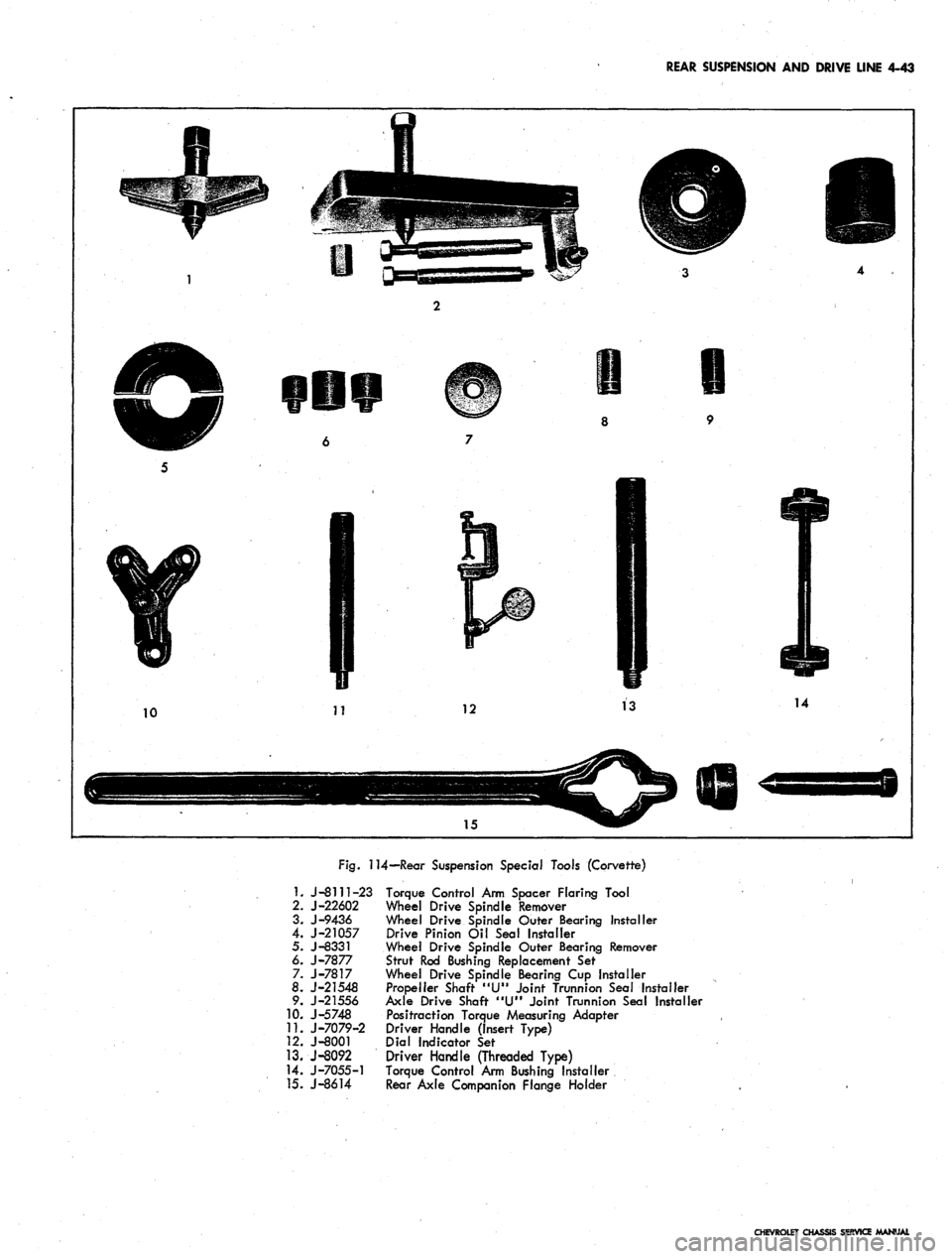
Fig.
114—Rear Suspension Special Tools (Corvette)
1.
J-8111-23 Torque Control Arm Spacer Flaring Tool
2.
J-22602 Wheel Drive Spindle Remover
3.
J-9436 Wheel Drive Spindle Outer Bearing Installer
4.
J-21057 Drive Pinion Oil Seal Installer
5. J-8331 Wheel Drive Spindle Outer Bearing Remover
6.
J-7877 Strut Rod Bushing Replacement Sef
7. J-7817 Wheel Drive Spindle Bearing Cup Installer
8.
J-21548 Propeller Shaft "U" Joint Trunnion Seal Installer
9. J-21556 Axle Drive Shaft "U" Joint Trunnion Sea! Installer
10.
J-5748 Positraction Torque Measuring Adapter
11.
J-7079-2 Driver Handle (Insert Type)
12.
J-8001 Dial Indicator Set
13.
J-8092 Driver Handle (Threaded Type)
14.
J-7055-1 Torque Control Arm Bushing Installer
15.
J-8614 Rear Axle Companion Flange Holder
CHEVROLET CHASSIS SERVICE MANUAL
Page 234 of 659
BRAKES
SECTION 5
CONTENTS OF THIS SECTION
Duo Servo Brakes
Disc Brakes
Page
5-1 Power Brakes
5-24 Special Tools
Page
5-31
5-32
DUO-SERVO BRAKES
INDEX
Page
General Description 5-1
Maintenance and Adjustments 5-3
Hydraulic Brake Fluid .. . 5-3
Bleeding Hydraulic System 5-3
Pressure Bleeding 5-3
Manual Bleeding 5_4
Push Rod to Main Cylinder Clearance 5-5
Hydraulic Brake Lines 5-5
Hydraulic Brake Hose 5-5
Hydraulic Brake Tubing 5-6
Brake Adjustment. .................... 5-7
Service Brake 5-7
Parking Brake 5-8
Component Replacement and Repairs 5-9
Parking Brake - Chevrolet, Chevelle and
Camaro 5^9
Pedal Assembly 5-9
Front Cable ,. . . 5-9
Center Cable 5-9
Rear Cables. . 5-9
Parking Brake - Chevy n 5-9
Lever Assembly 5-9
Idler Lever 5-11
Front Cable 5-11
Rear Cable . . ; 5-12
Parking Brake - Corvette 5-13
Lever Assembly . . . . 5-13
Front Cable 5-14
Rear Cable . . 5-14
Brake Pedal 5-15
Shoes and Linings 5-16
Organic 5-16
Metallic 5-17
Main Cylinder 5-18
Wheel Cylinders 5-21
Anchor Pin 5-22
Front Wheel 5-22
Rear Wheel 5-22
Brake Drums • 5-22
Brake Pipe Distribution and Switch Assembly . . . . . 5-23
Camaro Pressure Regulator Valve 5-23
GENERAL DESCRIPTION
All 1967 models are equipped with a new split brake
system as a safety feature. If a wheel cylinder or brake
line should fail at either the front end or rear end of
the vehicle, the operator can still bring the vehicle to
a controlled stop. The system is designed with separate
hydraulic systems for the front and rear brake using
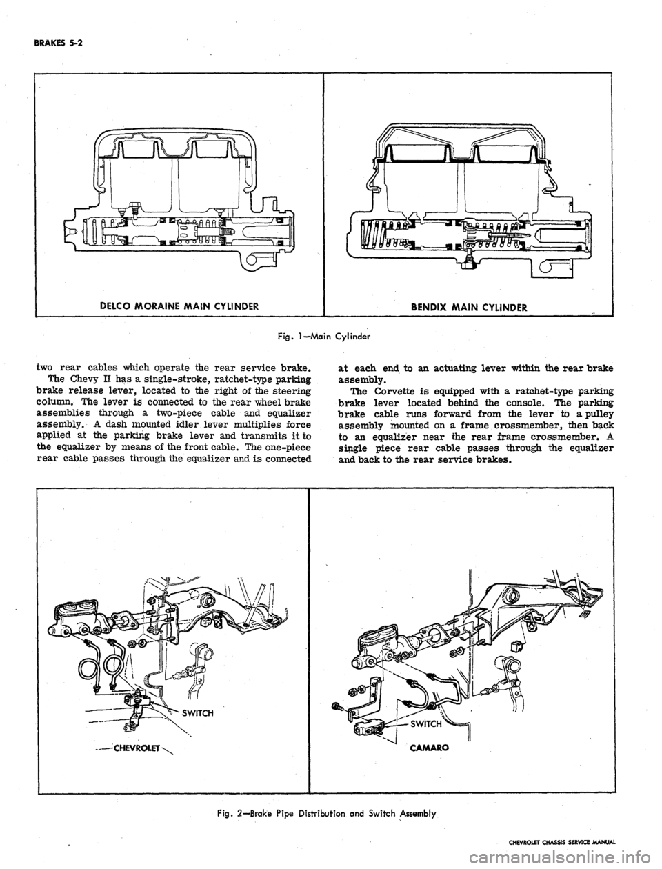
a dual master cylinder (fig. 1). The design of the master
cylinder is similar to that used on the 1966 Corvette
in that it has two entirely separate reservoirs and outlets
in a common body casting. The front reservoir and outlet
is connected to the front wheel brakes, and the rear
reservoir and outlet is connected to the rear wheel
brakes. Two pistons within the master cylinder receive
mechanical pressure from the brake pedal push rod and
transmit it through the brake lines as hydraulic pressure
to the wheel cylinders. The filler cap is accessible from
inside the engine compartment.
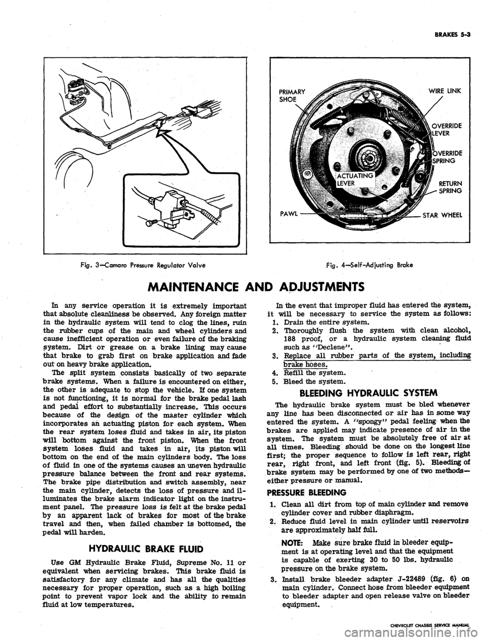
A new brake pipe distribution and switch assembly
is mounted below the main cylinder. The front and rear
hydraulic brake lines are routed from the main cylinder,
through the brake pipe distribution and switch assembly,
to the front and rear brakes as shown in Figure 2. The
switch is wired electrically to the brake alarm indicator
light on the instrument panel. In the event of fluid loss
in either the front or rear brake system the indicator
on the instrument panel will illuminate red. (The indi-
cator will also' be illuminated when the parking brake is
applied.)
On Camaro models equipped with air conditioning, the
rear brake hydraulic line is routed through a pressure
regulator valve mounted on the left frame side rail
(fig. 3). The valve controls the hydraulic pressure to
the rear brakes resulting in the correct pressure balance
between the front and rear hydraulic systems.
The self-adjusting brakes (fig. 4), used on both front
and rear of all models, are the Duo-Servo single anchor
type which utilize the momentum of the vehicle to assist
in the brake application. The self-energizing or
self-
actuating force is applied to both brake shoes at each
wheel in both forward and reverse motion. The brake
shoe linings are bonded to the shoes.
Wheel cylinders are the double piston type permitting
even distribution of pressure to each brake shoe. To
keep out dust and moisture, both ejads of each wheel
cylinder are sealed with a rubber booC The wheel
cylinders have no adjustments.
The Chevrolet, Chevelle, and Camaro parking brakes
have a foot operated ratchet type pedal mounted to the
left of the steering column. A cable assembly connects
the pedal to an intermediate cable by means of an equal-
izer, where the adjustment for the parking brake is
incorporated. The intermediate cable attaches to the
CHEVROLET CHASSIS SERVICE MANUAL
Page 235 of 659
BRAKES 5-2
DELCO MORAINE MAIN CYLINDER
BENDIX MAIN CYLINDER
Fig.
I—Main
Cylinder
two rear cables which operate the rear service brake.
The Chevy II has a single-stroke, ratchet-type parking
brake release lever, located to the right of the steering
column. The lever is connected to the rear wheel brake
assemblies through a two-piece cable and equalizer
assembly. A dash mounted idler lever multiplies force
applied at the parking brake lever and transmits it to
the equalizer by means of the front cable. The one-piece
rear cable passes through the equalizer and is connected
at each end to an actuating lever within the rear brake
assembly.
The Corvette is equipped with a ratchet-type parking
brake lever located behind the console. The parking
brake cable runs forward from the lever to a pulley
assembly mounted on a frame crossmember, then back
to an equalizer near the rear frame crossmember. A
single piece rear cable passes through the equalizer
and back to the rear service brakes.
— CHEVROLET
CAMARO
Fig.
2—Brake Pipe Distribution and Switch Assembly
CHEVROLET CHASSIS SERVICE MANUAL
Page 236 of 659
BRAKES
5-3
PRIMARY
SHOE
PAWL
WIRE LINK
OVERRIDE
LEVER
VERRIDE
SPRING
RETURN
SPRING
STAR
WHEEL
Fig.
3—Camaro
Pressure
Regulator
Valve
Fig.
4-Self-Adjusting
Brake
MAINTENANCE AND ADJUSTMENTS
In any service operation it is extremely important
that absolute cleanliness be observed. Any foreign matter
in the hydraulic system will tend to clog the lines, ruin
the rubber cups of the main and wheel cylinders and
cause inefficient operation or even failure of the braking
system. Dirt or grease on a brake lining may cause
that brake to grab first on brake application and fade
out on heavy brake application.
The split system consists basically of two separate
brake systems. When a failure is encountered on either,
the other is adequate to stop the vehicle. If one system
is not functioning, it is normal for the brake pedal lash
and pedal effort to substantially increase. This occurs
because of the design of the master cylinder which
incorporates ah actuating piston for each system. When
the rear system loses fluid and takes in air, its piston
will bottom against the front piston. When the front
system loses fluid and takes in air, its piston will
bottom on the end of the main cylinders body. The loss
of fluid in one of the systems causes an uneven hydraulic
pressure balance between the front and rear systems.
The brake pipe distribution and switch assembly, near
the main cylinder, detects the loss of pressure and il-
luminates the brake alarm indicator light on the instru-
ment panel. The pressure loss is felt at the brake pedal
by an apparent lack of brakes for most of the brake
travel and then, when failed chamber is bottomed, the
pedal will harden.
HYDRAULIC BRAKE FLUID
Use GM Hydraulic Brake Fluid, Supreme No. 11 or
equivalent when servicing brakes. This brake fluid is
satisfactory for any climate and has all the qualities
necessary for proper operation, such as a high boiling
point to prevent vapor lock and the ability to remain
fluid at low temperatures.
In the event that improper fluid has entered the system,
it will be necessary to service the system as follows:
1.
Drain the entire system.
2.
Thoroughly flush the system with clean alcohol,
188
proof,
or a hydraulic system cleaning fluid
such as "Declene".
3.
Replace all rubber parts of the system, including
brake hoses.
4.
Refill the system.
5. Bleed the system.
BLEEDING HYDRAULIC SYSTEM
The hydraulic brake system must be bled whenever
any line has been disconnected or air has in some way
entered the system. A ''spongy" pedal feeling when the
brakes are applied may indicate presence of air in the
system. The system must be absolutely free of air at
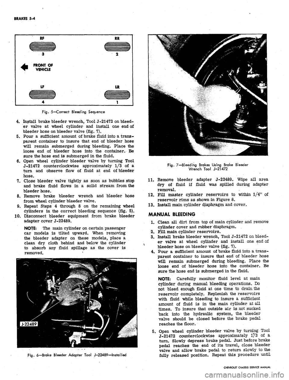
all times. Bleeding should be done on the longest line
first; the proper sequence to follow is left rear, right
rear, right front, and left front (fig. 5). Bleeding of
brake system may be performed by one of two methods—
either pressure or manual.
PRESSURE
BLEEDING
1.
Clean all dirt from top of main cylinder and remove
cylinder cover and rubber diaphragm.
2.
Reduce fluid level in main cylinder until reservoirs
are approximately half full.
NOTE:
Make sure brake fluid in bleeder equip-
ment is at operating level and that the. equipment
is capable of exerting 30 to 50 lbs. hydraulic
pressure on the brake system.
3.
Install brake bleeder adapter J-22489 (fig. 6) on
main cylinder. Connect hose from bleeder equipment
to bleeder adapter and open release valve on bleeder
equipment.
CHEVROLET CHASSIS SERVICE MANUAL
Page 237 of 659
BRAKES 5-4
RF
3
^ FRONT OF
~ VEHICLE
LF
4
RR
CZZZIZ3
2
LR
1
Fig.
5—Correct Bleeding Sequence
4.
Install brake bleeder wrench, Tool J-21472 on bleed-
er valve at wheel cylinder and install one end of
bleeder hose on bleeder valve (fig. 7).
5.
Pour a sufficient amount of brake fluid into a trans-
parent container to insure that end of bleeder hose
will remain submerged during bleeding. Place the
loose end of bleeder hose into the container. Be
sure the hose end is submerged in the fluid.
6. Open wheel cylinder bleeder valve by turning Tool
J-21472 counterclockwise approximately 1/3 of a
turn and observe flow of fluid at end of bleeder
hose.
7.
Close bleeder valve tightly as soon as bubbles stop
and brake fluid flows in a solid stream from the
bleeder hose.
8. Remove brake bleeder wrench and bleeder hose
from wheel cylinder bleeder valve.
9. Repeat Steps 4 through 8 on the remaining wheel
Cylinders in the correct bleeding sequence (fig. 5).
10.
Disconnect bleeder equipment from brake bleeder
adapter cover J-22489.
NOJE: The main cylinder on certain passenger
car models is tilted upward. When removing
the bleeder adapter on these models, place a
clean dry cloth behind and below the cylinder
to absorb any fluid spillage as the cover is
removed. v
Fig.
7—Bleeding Brakes Using Brake Bleeder
Wrench Tool J-21472
11.
adapter J-22489. Wipe all area
fluid was spilled during adapter
Fig.
6—Brake Bleeder Adapter Tool J-22489—Installed
Remove bleeder
dry of fluid if
removal.
12.
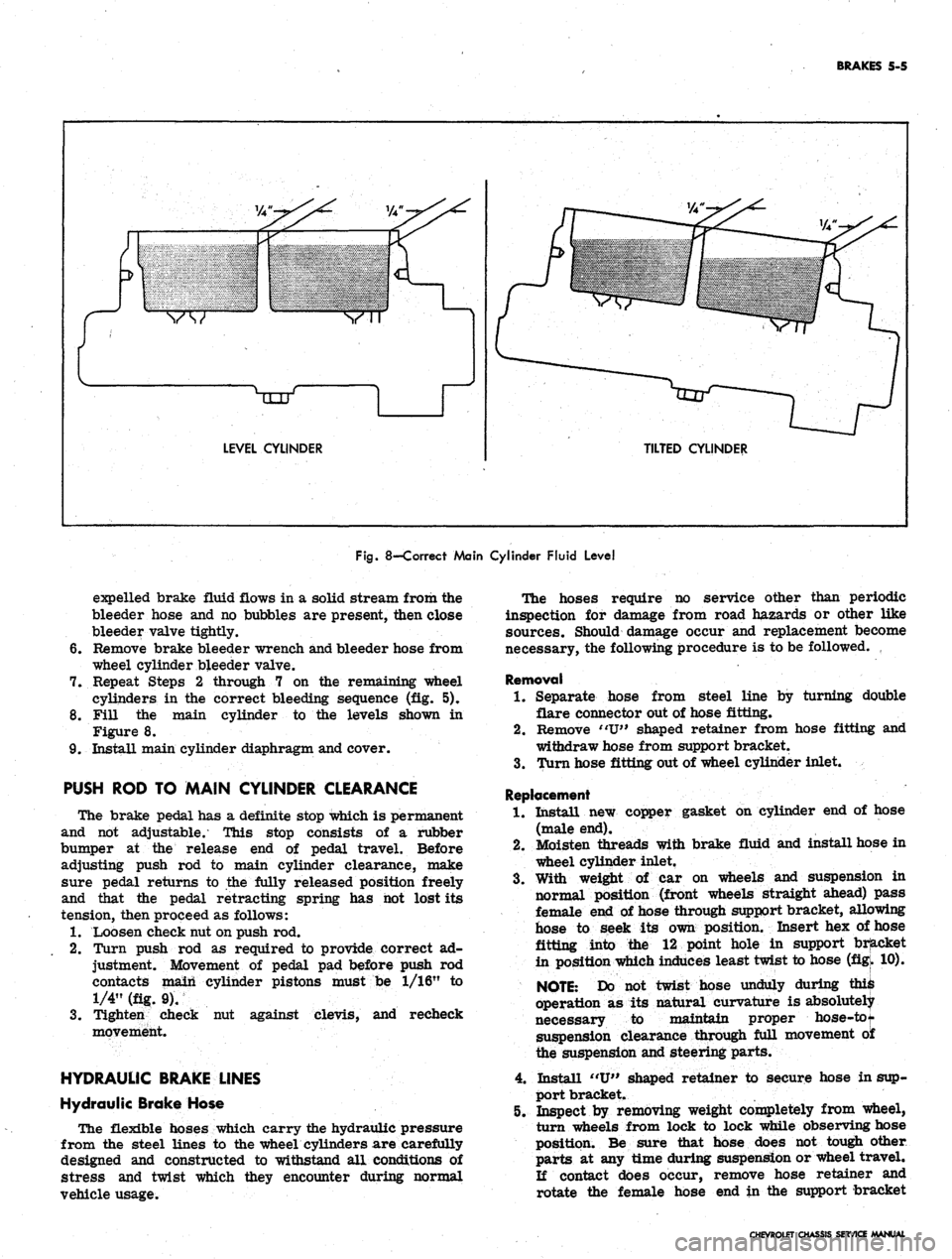
Fill master cylinder reservoirs to within 1/4" of
reservoir rims as shown in Figure 8.
13.
Install main cylinder diaphragm and cover.
MANUAL BLEEDING
1.
Clean all dirt from top of main cylinder and remove
cylinder cover and rubber diaphragm.
2.
Fill main cylinder reservoirs.
3.
Install brake bleeder wrench, Tool J-21472 on bleed-
er valve at wheel cylinder and install one end of
bleeder hose on bleeder valve (fig. 7).
4.
Pour a sufficient amount of brake fluid into a trans-
parent container to insure that end of bleeder hose
will remain submerged during bleeding. Place the
loose end of bleeder hose into the container. Be
sure the hose end is submerged in the fluid.
NOTE: Carefully monitor fluid level at main
cylinder during manual bleeding operations. Do
not bleed enough fluid at one time to drain the
reservoir completely. Replenish the reservoirs
with fluid while bleeding to insure a sufficient
amount of fluid is in the main cylinder at all
times.
To insure that outside air is not sucked
back into the hydraulic system, the bleeder
valve should be closed before the brake pedal
reaches the floor.
5.
Open wheel cylinder bleeder valve by turning Tool
J-21472 counterclockwise approximately 1/3 of a
turn. Slowly depress brake pedal. Just before brake
pedal reaches the end of its travel, close bleeder
valve and allow brake pedal to return slowly to the
fully released position. Repeat this procedure until
CHEVROLET CHASSIS SERVICE MANUAL
Page 238 of 659
BRAKES 5-5
LEVEL CYLINDER
TILTED CYLINDER
Fig.
8—Correct Main Cylinder Fluid Level
expelled brake fluid flows in a solid stream from the
bleeder hose and no bubbles are present, then close
bleeder valve tightly.
6. Remove brake bleeder wrench and bleeder hose from
wheel cylinder bleeder valve.
7. Repeat Steps 2 through 7 on the remaining wheel
cylinders in the correct bleeding sequence (fig. 5).
8. Fill the main cylinder to the levels shown in
Figure 8.
9. Install main cylinder diaphragm and cover.
PUSH ROD TO MAIN CYLINDER CLEARANCE
The brake pedal has a definite stop which is permanent
and not adjustable. This stop consists of a rubber
bumper at the release end of pedal travel. Before
adjusting push rod to main cylinder clearance, make
sure pedal returns to the fully released position freely
and that the pedal retracting spring has hot lost its
tension, then proceed as follows:
1.
Loosen check nut on push rod.
2.
Turn push rod as required to provide correct ad-
justment. Movement of pedal pad before push rod
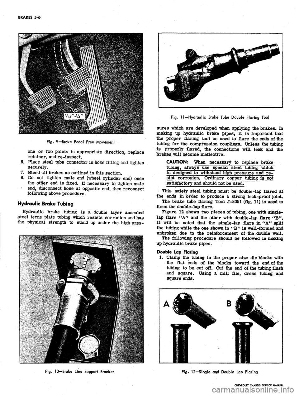
contacts main cylinder pistons must be 1/16" to
1/4" (fig. 9).
3.
Tighten check nut against clevis, and recheck
movement.
HYDRAULIC BRAKE LINES
Hydraulic Brake Hose
The flexible hoses which carry the hydraulic pressure
from the steel lines to the wheel cylinders are carefully
designed and constructed to withstand all conditions of
stress and twist which they encounter during normal
vehicle usage.
The hoses require no service other than periodic
inspection for damage from road hazards or other like
sources. Should damage occur and replacement become
necessary, the following procedure is to be followed.
Removal
1.
Separate hose from steel line by turning double
flare connector out of hose fitting.
2.
Remove "U" shaped retainer from hose fitting and
withdraw hose from support bracket.
3.
Turn hose fitting out of wheel cylinder inlet.
Replacement
1.
Install new copper gasket on cylinder end of hose
(male end).
2.
Moisten threads with brake fluid and install hose in
wheel cylinder inlet.
3.
With weight of car on wheels and suspension in
normal position (front wheels straight ahead) pass
female end of hose through support bracket, allowing
hose to seek its own position. Insert hex of hose
fitting into the 12 point hole in support bracket
in position which induces least twist to hose (figk 10).
NOTE:
Do not twist hose unduly during ^
operation as its natural curvature is absolutely
necessary to maintain proper hose-tot
suspension clearance through full movement o£
the suspension and steering parts.
4.
Install "U" shaped retainer to secure hose in sup-
port bracket.
5. Inspect by removing weight completely from wheel,
turn wheels from lock to lock while observing hose
position. Be sure that hose does not tough other
parts at any time during suspension or wheel travel.
If contact does occur, remove hose retainer and
rotate the female hose end in the support bracket
CHEVROLET CHASSIS SERVICE MANUAL
Page 239 of 659
BRAKES 5-6
Fig.
9—Brake Pedal Free Movement
one or two points in appropriate direction, replace
retainer, and re-inspect.
6. Place steel tube connector in hose fitting and tighten
securely.
7. Bleed all brakes as outlined in this section.
8. Do not tighten male end (wheel cylinder end) once
the other end is fixed. If necessary to tighten male
1 end, disconnect hose at opposite end, then reconnect
following above procedure.
Hydraulic Brake Tubing
Hydraulic brake tubing is a double layer annealed
steel terne plate tubing which resists corrosion and has
the physical strength to stand up under the high pr.es-
Fig.
11—Hydraulic Brake Tube Double Flaring Tool
sures which are developed when applying the brakes. In
making up hydraulic brake pipes, it is important that
the proper flaring tool be used to flare the ends of the
tubing for the compression couplings. Unless the tubing
is properly flared, the connections will leak and the
brakes will become ineffective.
CAUTION: When necessary to replace brake
tubing, always use special steel tubing which
is designed to withstand high pressure and re-
sist corrosion. Ordinary copper tubing is not
satisfactory and should not be used.
This safety steel tubing must be double-lap flared at
the ends in order to produce a strong leak-proof joint.
The brake tube flaring. Tool J-8051 (fig. 11) is used to
form the double-lap flare.
Figure 12 shows two pieces of tubing, one with single-
lap flare "A" and the other with double-lap flare "B".
It will be noted that the single-lap flare in "A" split
the tubing while the one shown in "B" is well-formed and
unbroken due to the reinforcement of the double wall.
The following procedure should be followed in making
up hydraulic brake pipes.
Double Lap Flaring
1.
Clamp the tubing in the proper size die blocks with
the flat ends of the blocks toward the end of the
tubing to be cut off. Cut the end of the tubing flush
and square. Using a mill file, dress tubing and
square ends.
Fig.
10-Brake Line Support Bracket
Fig.
12—Single and Double Lap Flaring
CHEVROLET CHASSIS SERVICE MANUAL
Page 240 of 659
BRAKES 5-7
LATCH PLATE
DIE BLOCK
TUBE
UPSET FLARE PUNCH
RAM GUIDE
STOP PLATE
Fig.
13—Flaring Operation--Position ing Tubing
2.
Remove the tubing from the die block and deburr
the inside and outside edges.
3.
Install compression couplings on tubing and dip end
of tubing to be flared in hydraulic fluid. This lubri-
cation results in better formation of the flare.
4.
Place on-half of the die blocks in the tool body with
the counterbored ends toward the ram guide. Now
lay the tubing in the block with approximately 1/2"
protruding beyond the end.
Fit the other half of the block into the tool body,
close the latch plate and tighten the nuts "finger
tight".
5. Select the correct size upset flare punch. One end
of this punch is counterbored or hollowed out to
gauge the amount of tubing necessary to form a
double lap flare. Slip the punch into the tool body
with the gauge end toward the die blocks. Install the
ram; then tap lightly until the punch meets the die
, blocks and they are forced securely against the
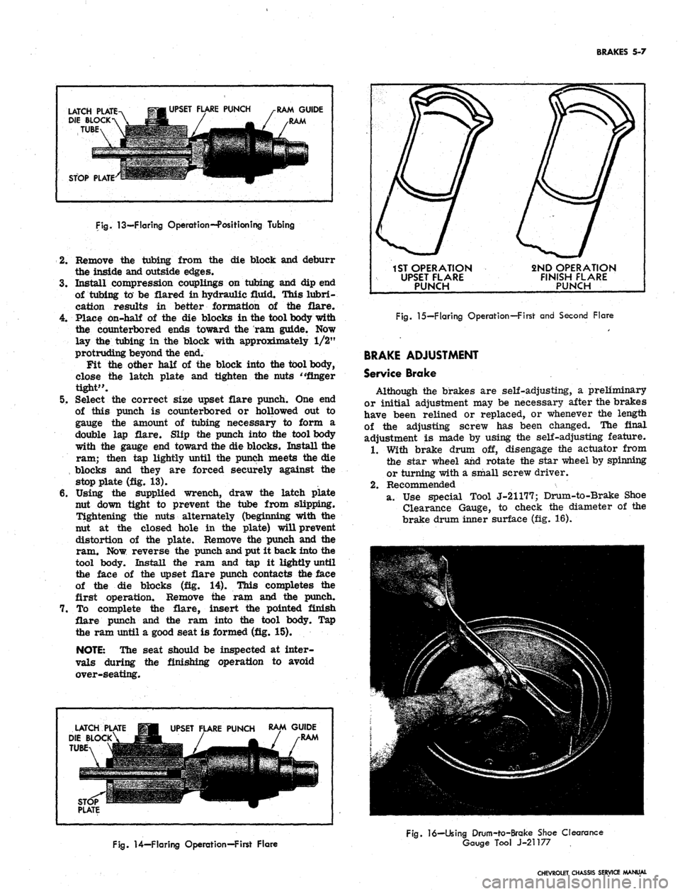
stop plate (fig. 13).
6. Using the supplied wrench, draw the latch plate
nut down tight to prevent the tube from slipping.
Tightening the nuts alternately (beginning with the
nut at the closed hole in the plate) will prevent
distortion of the plate. Remove the punch and the
ram. Now reverse the punch and put it back into the
tool body. Install the ram and tap it lightly until
the face of the upset flare punch contacts the face
of the die blocks (fig. 14). This completes the
first operation. Remove the ram and the punch.
7. To complete the flare, insert the pointed finish
flare punch and the ram into the tool body. Tap
the ram until a good seat is formed (fig. 15).
NOTE:
The seat should be inspected at inter-
vals during the finishing operation to avoid
over-seating.
LATCH
DIE BLOCK
TUBE
UPSET FLARE PUNCH
RAM GUIDE
RAM
1ST OPERATION
UPSET FLARE
PUNCH
2ND OPERATION
FINISH FLARE
PUNCH
Fig.
15—Flaring Operation—First and Second Flare
BRAKE ADJUSTMENT
Service Brake
Although the brakes are self-adjusting, a preliminary
or initial adjustment may be necessary after the brakes
have been relined or replaced, or whenever the length
of the adjusting screw has been changed. The final
adjustment is made by using the self-adjusting feature.
1.
With brake drum off, disengage the actuator from
the star wheel and rotate the star wheel by spinning
or turning with a small screw driver.
2.
Recommended
a. Use special Tool J-21177; Drum-to-Brake Shoe
Clearance Gauge, to check the diameter of the
brake drum inner surface (fig. 16).
Fig.
14—Flaring Operation—First Flare
Fig.
16—Using Drum-to-Brake Shoe Clearance
Gauge Tool J-21177
CHEVROLET CHASSIS SERVICE MANUAL