CHEVROLET CAMARO 1967 1.G Chassis Workshop Manual
Manufacturer: CHEVROLET, Model Year: 1967, Model line: CAMARO, Model: CHEVROLET CAMARO 1967 1.GPages: 659, PDF Size: 114.24 MB
Page 251 of 659
BRAKES
5-18
Fig.
30—Checking
Operation
of the
Actuating
Lever
2.
Make six to eight complete stops from maximum
legal highway speed at approximately one mile inter-
vals to fully seat the linings.
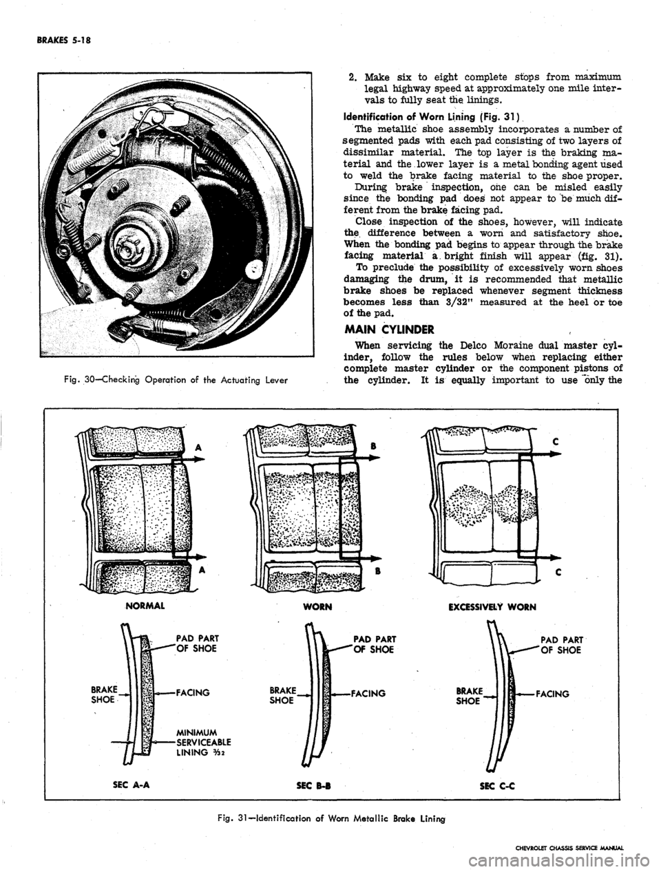
Identification of Worn Lining (Fig. 31)
The metallic shoe assembly incorporates a number of
segmented pads with each pad consisting of two layers of
dissimilar material. The top layer is the braking ma-
terial and the lower layer is a metal bonding agent used
to weld the brake facing material to the shoe proper.
During brake inspection, one can be misled easily
since the bonding pad does not appear to be much dif-
ferent from the brake facing pad.
Close inspection of the shoes, however, will indicate
the difference between a worn and satisfactory shoe.
When the bonding pad begins to appear through the brake
facing material a bright finish will appear (fig. 31).
To preclude the possibility of excessively worn shoes
damaging the drum, it is recommended that metallic
brake shoes be replaced whenever segment thickness
becomes less than 3/32" measured at the heel or toe
of the pad.
MAIN CYLINDER
When servicing the Delco Moraine dual master cyl-
inder, follow the rules below when replacing either
complete master cylinder or the component pistons of
the cylinder. It is equally important to use 'only the
NORMAL
WORN
EXCESSIVELY
WORN
BRAKE
SHOE
PAD PART
'OF SHOE
•FACING
MINIMUM
•SERVICEABLE
LINING
%2
BRAKE
SHOE
PAD PART
OF SHOE
FACING
BRAKE
SHOE
PAD PART
OF SHOE
FACING
SEC
A-A
SEC
B-B
SEC
C-C
Fig. 31—Identification of Worn Metallic Brake Lining
CHEVROLET CHASSIS SERVICE MANUAL
Page 252 of 659
BRAKES 5-19
correct service parts when servicing a Bendix main
cylinder.
1.
The two-letter identification stamp on the end of
the master cylinder indicates the displacement capa-
bilities of that particular cylinder. Master cylinders
should only be replaced with another cylinder bearing
the same two-letter identification.
2.
The length of the component pistons in the master
cylinders are critical factors in displacement capa-
bilities of a particular master cylinder. These
pistons are coded, using rings or grooves in the
shank of the piston. It is mandatory that when
pistons are replaced, the replacing piston must con-
tain the same identification marks and the same
contour at the push rod end as the piston which
is removed.
Delco Moraine dual master cylinders, used with
drum-type brakes, contain a rubber check valve and
check valve spring in each outlet boss. When the
car is equipped with disc brakes on the front and
drum brakes on the rear, the dual master cylinder
will have a check valve and spring in the outlet
boss for the rear brakes. No check valve is required
for four wheel disc brakes, and, therefore, the outlet
1.
Spring
2.
Check Valve
3. Valve Seat
4.
Bleeder Valve
5. Bail Wire
6. Cover
7. Diaphragm
8. Stop Screw
9. Body
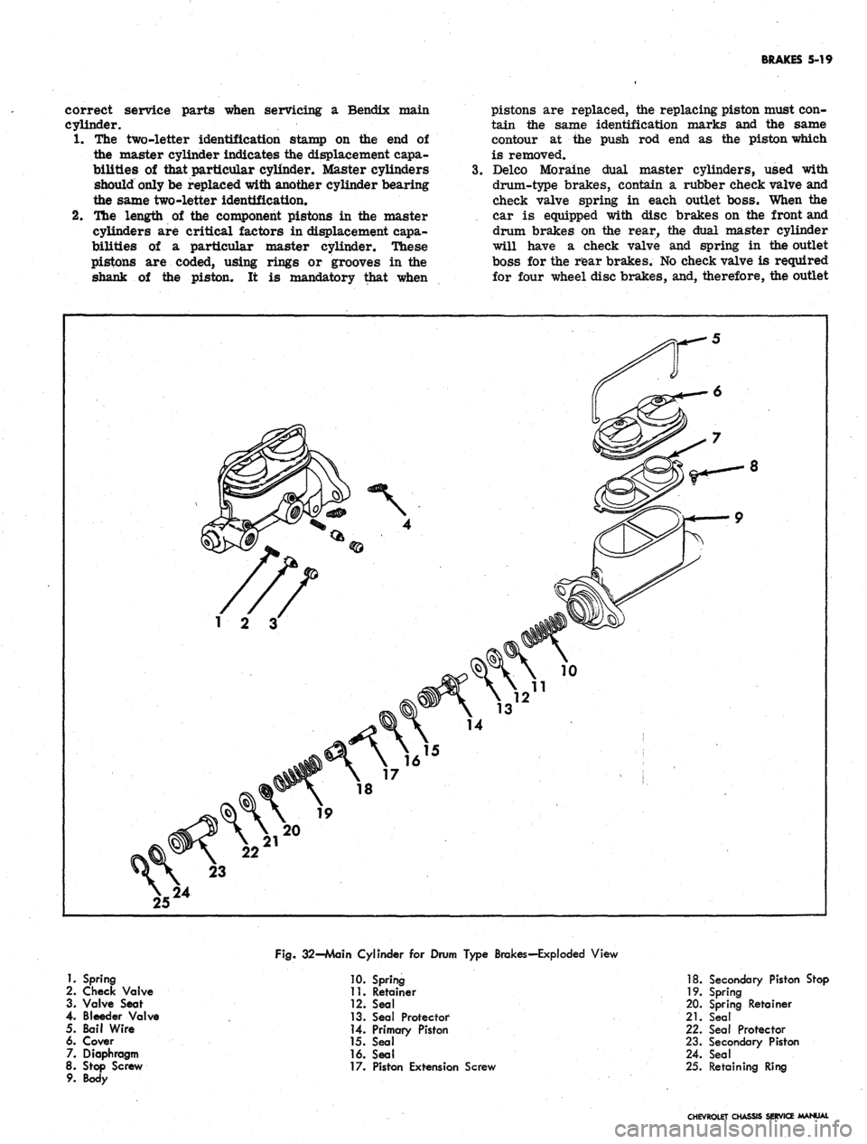
Fig.
32-Main Cylinder for Drum Type Brakes-Exploded View
10.
Spring
11.
Retainer
12.
Seal
13.
Seal Protector
14.
Primary Piston
15.
Seal
16.
Seal
17.
Piston Extension Screw
18.
Secondary Piston Stop
19.
Spring
20.
Spring Retainer
21.
Seal
22.
Seal Protector
23.
Secondary Piston
24.
Seal
25.
Retaining Ring
CHEVROLET CHASSIS SERVICE MANUAL
Page 253 of 659
BRAKES 5-20
boss to the front brakes will not contain a check
valve and spring. .
Removal
1.
Wipe main cylinder and lines clean with a clean
cloth. Place dry cloths below main cylinder area to
absorb any fluid spillage.
2.
Disconnect hydraulic lines at main cylinder. Cover
line ends with clean lint-free material to prevent
foreign matter from entering the system.
3.
Disconnect the push rod from the brake pedal.
4.
Unbolt and remove the main cylinder from the
firewall.
5.
Remove the main cylinder mounting gasket and boot.
6. Remove the main cylinder cover and dump out the
fluid. Pump the remaining fluid from the cylinder
by depressing the push rod.
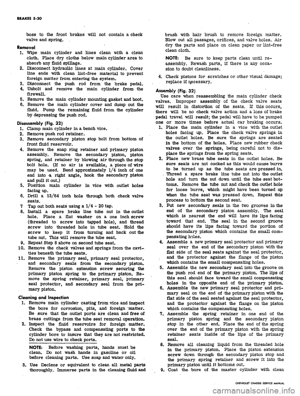
Disassembly (Fig. 32)
1.
Clamp main cylinder in a bench vice.
2.
Remove push rod retainer.
3.
Remove secondary piston stop bolt from bottom of
front fluid reservoir.
4.
Remove the snap ring retainer and primary piston
assembly. Remove the secondary piston, piston
spring, and retainer by blowing air through the stop
bolt hole. (If no air is available, a piece of wire
may be used. Bend approximately 1/4 inch of one
end into -a right angle, hook the secondary piston
and pull it out.)
5.
Position main cylinder in vice with outlet holes
facing up.
6. Drill a 13/64 inch hole through both check valve
seats.
7 Tap out both seats using a 1/4 - 20 tap.
8. Install a spare brake line tube nut in the outlet
hole.
Place a flat washer on a one inch screw
(threaded to screw into tapped hole), and thread
screw into threaded hole in tube seat. Hold the
screw to keep it from turning and back out the
tube nut. This will remove the tube seat.
9. Repeat Step 8 above on second tube seat.
10.
Remove the check valves and springs from the cavi-
ties beneath the tube seats.
11.
Remove the primary seal, primary seal protector,
and secondary seals from the secondary piston.
Remove the piston extension screw securing the
primary piston spring to the primary piston. Re-
move the spring retainer, primary seal, primary
seal protector, and secondary seal from the pri-
mary piston.
Cleaning and Inspection
1.
Remove main cylinder casting from vice and inspect
the bore for corrosion, pits, and foreign matter.
Be sure that the outlet ports are clean and free of
brass cuttings from the tube seat removal operation.
2.
Inspect the fluid reservoirs for foreign matter.
Check the bypass and compensating ports to the
cylinder bore to insure that they are not restricted.
Do not use wire to check ports.
NOTE: Before washing parts, hands must be
clean. Do not wash hands in gasoline or oil
before cleaning parts. Use soap and water only.
3.
Use Declene or equivalent to clean all metal parts
thoroughly. Immerse parts in the cleaning fluid and
brush with hair brush to remove foreign matter.
Blow out all passages, orifices, and valve holes. Air
dry the parts and place on clean paper or lint-free
clean cloth.
NOTE: Be sure to keep parts clean until re-
assembly. Rewash parts, if there is any occa-
sion to doubt cleanliness.
4.
Check pistons for scratches or other visual damage;
replace if necessary.
Assembly (Fig. 32)
Use care when reassembling the main cylinder check
valves. Improper assembly of the check valve seats
will result in distortion of the seats. If this occurs,
there will be no check valve action and a loss of brake
pedal travel will result; the pedal will have to be pumped
one or more times before actual car braking occurs.
1.
Place the main cylinder in a vice with the outlet
holes facing up. Place the check valve springs, in
the outlet holes. Be sure the springs are seated
in the bottom of the holes. Place new rubber check
valves over the springs, being careful not to dis-
place the springs from the spring seats.
2.
Place new brass tube seats in the outlet holes. Be
sure seats are not cocked as this would cause burrs
to be turned up as the tube seats are pressed in.
. Thread a spare brake line tube nut into the outlet
hole and turn the nut down until the tube seat bot-
toms.
Remove the tube nut and check the outlet hole
for loose burrs, which might have been turned up
when the tube seat was pressed down. Repeat this
process to bottom the second seat.
3.
Put new secondary seals in the two grooves in the
end of the secondary piston assembly. The seal
which is nearest the end will have its lips facing
toward that end. The seal in the second groove
should have its lips facing toward the portion of
the secondary piston which contains the small com-
pensating holes.
4.
Assemble a new primary seal protector and primary
seal over the end of the secondary piston with the
flat side of the seal seats against the seal protector,
and the protector against the flange of the piston
which contains the small compensating holes.
5.
Assemble the new secondary seal into the groove on
the push rod end of the primary piston. The lips of
this seal should face toward the small compensating
holes in the opposite end of the primary piston.
6. Assemble the new primary seal protector and pri-
mary seal on the end of-the primary piston with the
flat side of the. seal seated against the seal protector,
and the protector against the flange on the piston
which contains the compensating holes.
7.
Assemble the spring retainer in one end of the
primary piston spring and the secondary piston
stop in the other end. Place the end of the spring
over the end of the primary piston with the spring
retainer seats inside of the lips of the primary
seal.
8. Remove all cleaning liquid from the threaded hole
in the primary piston. Place the piston extension
screw down through the secondary piston stop and
the primary spring retainer and screw it into the
primary piston until it bottoms out.
9. Coat the bore of the master cylinder with clean
CHEVROLET CHASSIS SERVICE MANUAL
Page 254 of 659
BRAKES 5-21
brake fluid. Coat the primary and secondary seals
on the secondary piston with clean brake fluid. Insert
the secondary piston spring retainer into the sec-
ondary piston spring. Place the retainer and spring
down over the end of the secondary piston until the
retainer locates inside of the lips of the primary
cup.
10.
Hold the master cylinder with the open end of the
bore down. Push the secondary piston into the bore
until the spring seats against the closed end of the
bore.
11.
Position the master cylinder in a vise with the
open end of the bore up. Coat the primary and
secondary seal on the primary piston with clean
brake fluid. Push the primary piston assembly,
spring end first, into the bore of the master cylinder*
Hold the piston down and snap the lock ring into
position in the small groove in the I.D. of the bore.
12.
Push the primary piston down to move the secondary
piston forward far enough to clear the stop screw
hole in the bottom of the front fluid reservoir. Install
the stop screw.
13.
Install reservoir diaphragm in the reservoir cover
and install the cover on the main cylinder. Push
bail wire into position to secure the reservoir cover.
Installation
1.
Assemble the push rod through the push rod retainer,
if it has been disassembled.
2.
Push the retainer over the end of the main cylinder.
Assemble new boot over push rod and press it down
over the push rod retainer. Slide new mounting
gasket into position.
3.
Secure .the main cylinder to the firewall with mount-
ing bolts.
4.
Connect the push rod clevis to the brake pedal with
pin and retainer.
5. Connect the brake lines to the main cylinder.
6. Fill the main cylinder reservoirs to the levels
shown in Figure 8. Bleed the brake system as out-
lined in this section.
7. K necessary, adjust the brake pedal free play as
outlined in this section.
WHEEL CYLINDER (Fig. 33)
The wheel cylinder boots should be removed from a
cylinder body only when they are visibly damaged or
leaking fluid. Wheel cylinders having torn, cut, or heat-
cracked boots should be completely overhauled.
Removal
1.
Raise vehicle and place on jack stands.
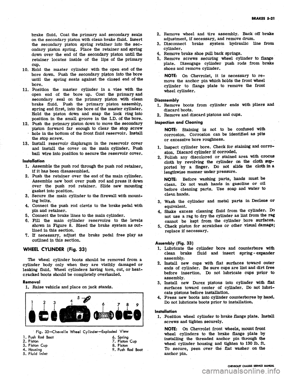
Fig.
33-Chevelle Wheel Cylinder—Exploded View
1.
Push Rod Boot 6. Spring
2.
Piston 7. Piston Cup
3. Piston Cup 8. Piston
4.
Housing 9. Push Rod Boot
5. Fluid Inlet
2.
Remove wheel and tire assembly. Back off brake
adjustment, if necessary, and remove drum.
3.
Disconnect brake system hydraulic line from
cylinder.
4.
Remove brake shoe pull back springs.
5. Remove screws securing wheel cylinder to flange
plate. Disengage cylinder push rods from brake
shoes and remove cylinder.
NOTE:
On Chevrolet, it is necessary to re-
move the anchor pin which holds the front wheel
cylinder to flange plate to remove the front
wheel cylinder.
Disassembly
1.
Remove boots from cylinder ends with pliers and
discard boots.
2.
Remove and discard pistons and cups.
Inspection and Cleaning
NOTE:
Staining is not to be confused with
corrosion. Corrosion can be identified as pits
or excessive bore roughness.
1.
Inspect cylinder bore. Check for staining and corro-
sion.
Discard cylinder if corroded.
2.
Polish any discolored or stained area with crocus
cloth by revolving the cylinder on the cloth sup-
ported by a finger. Do not slide tfce cloth in a
lengthwise manner under pressure.
NOTE:
Before washing parts, hands must be
clean. Do not wash hands in gasoline or oil
before cleaning parts. Use soap and water to
clean hands.
3.
Wash the cylinder and metal parts in Declene or
equivalent.
4.
Shake excess cleaning fluid from the cylinder-. Do
not use a rag to dry the cylinder as lint from the rag
cannot be kept from the cylinder bore surfaces.
5. Check piston for scratches or other visual damage;
replace if necessary.
Assembly (Fig. 33)
1.
Lubricate the cylinder bore and counterbore with
clean brake fluid and insert spring - expander
assembly.
2.
Install new cups with flat surfaces toward outer
ends of cylinder. Be sure cups are lint and dirt free
before insertion. Do not lubricate cups prior to
assembly.
3.
Install new Durex pistons into cylinder with flat
surfaces toward center of cylinder. Do not lubri-
cate pistons before installation.
4.
Press new boots into cylinder counterbores by hand.
Do not lubricate boots prior to installation.
Installation
1.
Position wheel cylinder to brake flange plate. Install
screws and tighten securely.
NOTE:
On Chevrolet front wheels, mount front
wheel cylinders to the brake flange plate by
installing the threaded anchor pin through the
wheel cylinder housing and tighten to 130 lb. ft.
To secure, peen over the flat washer on the
anchor pin.
CHEVROLET CHASSIS SERVICE MANUAL
Page 255 of 659
BRAKES 5-22
2.
Replace ail push rods and pull back springs.
3.
Connect hose or line to wheel cylinder.
NOTE:
If replacing front wheel cylinder, con-
nect hose and inspect installation as outlined in
"Hydraulic Brake Hose Replacement".
4.
Install drum and wheel.
5. Bleed brakes as outlined in this section.
ANCHOR PIN
Front Wheel
1.
Raise front of vehicle and place on jack stands.
2.
Remove wheel and drum as outlined in this section.
3.
Remove brake shoe pull back springs, link and guide
plate.
4.
Disengage anchor pin lock and remove anchor pin by
turning counterclockwise.
5. Place new lock plate on anchor pin and pass pin
through the hole in flange plate and screw into tapped
hole in spindle support.
6. Torque pin to 130 lb. ft. and lock by peening over
washer tabs.
7. Install brake shoe guide plate, link and pull back
springs.
8. Adjust brakes, install drum and wheel as outlined
in this section. Test brake operation.
Rear Wheel
Two type anchor pins are used in production for the
rear wheels. The riveted type is not serviced and if
failure or damage should occur to either the anchor
pin or flange plate, both parts will have to be replaced
and the threaded type anchor pin used.
Threaded Type
1.
Raise rear of vehicle and place on jack stands,
2.
Remove wheel and drum as outlined in this section.
3.
Remove brake shoe pull back springs, link and guide
plate.
4.
Remove anchor pin retaining nut and washer and
remove pin from flange plate.
5. Position anchor pin to flange plate, install lock
washer and nut, and torque pin to 80 lb. ft.
6. Install brake shoe guide plate, link and pull back
springs.
7. Adjust brakes and install drum and wheel as outlined
in this section.
8. Test brake operation.
BRAKE DRUMS
Front brake drums are the demountable type; that is,
they can be removed without removing the hub. Rear
brake drums are demountable and may be removed
wihtout removing the axle shaft.
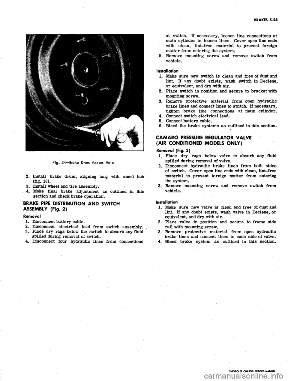
A lanced "knock out" area (fig. 34) is provided in
the web of the brake drum for servicing purposes in
the event retracting of the brake shoes is required in
order to remove the drum.
A small screw driver or hooked wire may be inserted
to disengage the automatic adjuster actuating lever so
the star wheel may be turned.
Removal
1.
Raise vehicle and place on jack stand.
2.
Remove wheel and tire assembly, back off brake
adjustment and remove drum.
Inspection and Reconditioning
Whenever brake drums are removed they should be
thoroughly cleaned and inspected for cracks, scores,
deep grooves, and out-of-round. Any of these conditions
must be corrected since they can impair the efficiency
of brake operation and also can cause premature failure
of other parts.
Smooth up any slight scores by polishing with fine
emery cloth. Heavy or extensive scoring will cause
excessive brake lining wear and it will probably be
necessary to rebore in order to true up the braking
surface.
An out-of-round drum makes accurate brake shoe
adjustment impossible and is likely to cause excessive
wear of other parts of brake mechanism due to its
eccentric action.
A drum that is more than .008" out-of-round on the
diameter is unfit for service and should be rebored.
Out-of^round, as well as taper and wear can be ac-
curately measured with an inside micrometer fitted
with proper extension rods.
If drum is to be rebored for use with standard size
brake facings which are worn very little, only enough
metal should be removed to obtain a true smooth braking
surface.
If drum has to be rebored more than .020" over the
standard diameter, it should be rebored to .060" diameter
oversize and the brake facing should be replaced with
.030"
oversize facings.
A brake drum must not be rebored more than .060"
over the maximum standard diameter, since removal
of more metal will effect, dissipation of heat and may
cause distortion of drum. Chevrolet brake facing is
not furnished larger than .030" oversize and this will
not work efficiently in drums bored more than .060"
oversize.
Brake drums may be refinished either by turning or
grinding. Best brake performance is obtained by turning
drums with a very fine feed. To insure maximum lining
life,
the refinished braking surface must be smooth and
free from chatter or tool marks, and run-out must not
exceed .005" total indicator reading.
Cleaning
New brake drums in parts stock are given a light.
coating of rust proofing oil to prevent the formation of
rust on the critical braking surfaces during the time
that the drums are in storage.
This rust proofing oil must be carefully removed
before the drum is placed in service to prevent any
of this oil from getting on the brake shoe facings, which
might cause an extreme brake grab condition.
It is recommended that a suitable volatile, non-toxic,
greaseless type solvent be used to clean the oil from the
braking surface of the new brake drums before they are
•placed in service to insure the cleanest possible surface.
Gasoline or kerosene should not be used as there is
danger that a portion of the diluated oil substance may
be left on the braking surface that may later cause
difficulty.
Installation
1.
Make brake adjustment as outlined in this section.
CHEVROLET CHASSIS SERVICE MANUAL
Page 256 of 659
BRAKES 5-23
Fig.
34—Brake Drum Access Hole
2.
Install brake drum, aligning tang with wheel hub
(fig. 18).
3.
Install wheel and tire assembly.
. 4. Make final brake adjustment as outlined in this
section and check brake operation.
BRAKE PIPE DISTRIBUTION AND SWITCH
ASSEMBLY (Fig. 2)
Removal
1.
Disconnect battery cable.
2.
Disconnect electrical lead from switch assembly.
3.
Place dry rags below the switch to absorb any fluid
spilled during removal of switch.
4.
Disconnect four hydraulic lines from connections
at switch. If necessary, loosen line connections at
main cylinder to loosen lines. Cover open line ends
with clean, lint-free material to prevent foreign
matter from entering the system.
5.
Remove mounting screw and remove switch from
vehicle.
Installation
1.
Make sure new switch is clean and free of dust and
lint. If any doubt exists, wash switch in Declene,
or equivalent, and dry with air.
2.
Place switch in position and secure to bracket with
mounting screw.
3.
Remove protective material from open hydraulic
brake lines and connect lines to switch. If necessary,
tighten brake line connections at main cylinder.
4.
Connect switch electrical lead.
5.
Connect battery cable.
6. Bleed the brake systems as outlined in this section.
CAMARO PRESSURE REGULATOR VALVE
(AIR CONDITIONED MODELS ONLY)
Removal (Fig. 3)
1.
Place dry rags below valve to absorb any fluid
spilled during removal of valve.
2.
Disconnect hydraulic brake lines from both sides
of switch. Cover open line ends with clean, lint-free
material to prevent foreign matter from entering
the system.
3.
Remove mounting screw and remove switch from
vehicle.
Installation
1.
Make sure new valve is clean and free of dust and
lint. If any doubt exists, wash valve in Declene, or
equivalent, and dry with air.
2.
Place valve in position and secure to frame side
rail with mounting screw.
3.
Remove protective material from open hydraulic
brake lines and connect lines to each side of valve.
4.
Bleed brake system as outlined in this section.
CHEVROLET CHASSIS SERVICE
Page 257 of 659
BRAKES
5-24
DISC BRAKES
INDEX
Page
General Description
. 5-24
Maintenance
and
Adjustments
5-24
Bleeding Hydraulic System
5-24
Parking Brake Adjustment
-
Corvette
5-24
Component Replacement
and
Repairs
5-25
Page
Brake Shoes
. . . . . 5-25
Brake Caliper
5-26
Brake Disc
5-29
Main Cylinder.
5-30
Parking Brake Shoes
-
Corvette
5-30
GENERAL DESCRIPTION
Four wheel disc brakes
are
standard equipment
on
the
1967
Corvette,
as in 1966. The
Corvette
may
also
be equipped with heavy duty disc brakes which include
new front calipers, shoes, linings,
and
rear pressure
regulator valve. This heavy duty option
is
used
in
conjunction with
a
vacuum power unit. Front wheel disc
brakes
are
installed
as
optional equipment
on
Chevrolet,
Chevelle, Camaro,
and
Chevy
II
models.
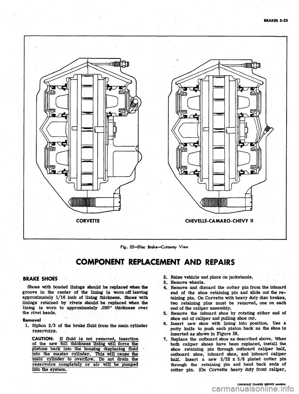
The disc brake,
(fig. 35),
consists
of a
fixed caliper,
rotating disc, splash shield,
and
mounting bracket.
The
caliper assembly contains four pistons and two shoe
and
lining assemblies with
the
lining riveted
to the
steel
shoes.
A
seal
and
dust boot
are
installed
on
each piston,
with
a
piston spring
in the
caliper cylinder bore beneath
each piston.
A
retaining pin extends through each caliper
half
and
both shoes
to
hold
the
shoes and linings
in
posi-
tion
in the
caliper.
On
Corvette heavy duty disc brakes,
two retaining cotter pins
are
used
at
each end
of the
caliper
to
secure
the
shoes
and
linings. Machined
sur-
faces within
the
caliper prevent
the
shoe
and
lining
assembly from rotating with
the
brake disc when pres-
sure
is
applied.
The disc, which
has a
series
of air
vent louvers
to
provide cooling,
is
mounted
on the
front wheel-hub.
The caliper straddles
the
disc and mounts
on a
mounting
bracket attached
to the
steering knuckle with
two
bolts.
The Corvette heavy duty option includes
a
pressure
regulator valve mounted
in the
rear brake line just
below
the
main cylinder. Chevrolet, Chevelle, Camaro,
and Chevy
n
models with disc brakes have
a
pressure
regulator valve mounted
in the
front brake line just
below
the
main cylinder. The valve controls
the
hydraulic
pressure
to the
front
or
rear brakes,
as
applicable,
resulting,
in the
correct pressure balance between
the
front
and
rear hydraulic systems. This valve guards
against premature .lock-up
of
front
or
rear wheels when
brakes
are
applied.
Maintenance, adjustment,
and
service operations which
are
not
included
in
this section
are the
same
as for
the Duo-Servo type brakes.
MAINTENANCE
AND
ADJUSTMENTS
BLEEDING HYDRAULIC SYSTEM
The operation
of
bleeding
the
disc brake hydraulic
system
is the
same
as for
Duo-Servo system outlined
in
the
front
of
this section. Note
the
exceptions below
and refer
to
bleeding procedures under Duo-Servo
brakes.
1.
When pressure bleeding equipment
is
used,
the
correct pressure setting
for
bleeding disc brakes
is 10-2.0
lbs. on
Corvette,
and 40 lbs. on all
other
models.
2.
The
front calipers contain
one
bleeder valve.
The
rear calipers
on
Corvette contain two bleeder valves
(one inboard
and one
outboard) which necessitates
the removal
of the
rear wheels
for
bleeding.
3.
Tapping
the
caliper with
a
rawhide mallet
as the
fluid
is
flowing
out may
assist
in
obtaining
a
good
bleeding
job.
4.
On
Chevrolet, Chevelle, Camaro
and
Chevy
II, the
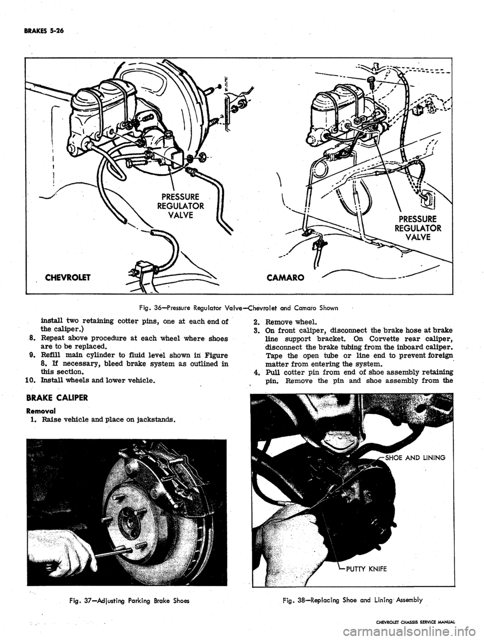
spring loaded
end of the
pressure regulator valve
(fig.
36)
must
be
held (valve
in
open position) while
bleeding. This
is
done
by
depressing
and
holding
in
the
plunger
in the
end
of
the valve either
by
hand,
by taping,
or by
clamping.
PARKING BRAKE-CORVETTE
Adjustment
1.
Raise rear
end of
vehicle
and
place
on
jack stands.
2.
Remove rear wheels.
3/
Loosen brake cables
at the
equalizer until
the
park-
ing brake levers move freely
to the "off"
position
with slack
in the
cables.
4.
Turn
the
disc until
the
adjusting screw can
be
seen
through
the
hole
in the
disc.
5. Insert
an
adjusting tool
or
screw driver through
the
hole
in the
disc
and
tighten
the
adjusting screw
by
moving your hand away from
the
floor
on
both
the
left and right sides
(fig. 37).
6. Tighten until
the
disc will
not
move, then back
off
ten
(10)
notches.
7. Apply
the
parking brake four
(4)
notches from inside
the
car.
8. Tighten
the
brake cables
at the
equalizer
to
produce
a light drag with
the
wheels mounted.
9. Fully release
the
parking brake handle
and
rotate
the rear wheels.
No
drag should be evident with
the
handle released.
CHEVROLET CHASSIS SERVICE MANUAL
Page 258 of 659
BRAKES 5-25
CORVETTE
CHEVELLE-CAMARO-CHEVY II
Fig.
35-Disc Brake-Cutaway View
COMPONENT REPLACEMENT AND REPAIRS
BRAKE SHOES
Shoes 'with bonded linings should be replaced when the
groove in the center of the lining is worn off leaving
approximately 1/16 inch of lining thickness. Shoes with
linings retained by rivets should be replaced when the
lining is worn to approximately .020" thickness over
the rivet heads.
Removal
1.
Siphon 2/3 of the brake fluid from the main cylinder
reservoirs.
CAUTION: If fluid is not removed, insertion
of the new full thickness lining will force the
pistons back into the housing displacing fluid •••
into the master cylinder. This will cause fee
main cylinder to overflow,, Do not drain the
reservoirs completely or air will be pumped
into the system. ~
2.
Raise vehicle and place on jackstands.
3..
Remove wheels.
4.
Remove and discard the cotter pin from the inboard
end of the shoe retaining pin and slide out the re-
taining pin. On Corvette with heavy duty disc brakes,
two retaining pins must be removed, one on each
end of the caliper assembly.
5. Remove the inboard shoe by rotating either end of
shoe out of caliper and pulling shoe out.
6. Insert new shoe with lining into position. Use a
putty knife to push each piston back as the shoe is
inserted as shown in Figure 38.
7. Replace the outboard shoe as described above. When
both caliper shoes have been replaced, install the
shoe retaining pin through outboard caliper
half,
outboard shoe, inboard shoe, and inboard caliper
half.
Insert a new 3/32 x 5/8 plated cotter pin
through the retaining pin and bend back ends of
cotter pin. (On Corvette heavy duty front caliper,
CHEVROLET CHASSIS SERVICE
Page 259 of 659
BRAKES 5-26
PRESSURE
REGULATOR
VALVE
CHEVROLET
PRESSURE
REGULATOR
VALVE
CAMARO
Fig.
36—Pressure Regulator Valve—Chevrolet and Camaro Shown
install two retaining cotter pins, one at each end of
the caliper.)
8. Repeat above procedure at each wheel where shoes
are to be replaced.
9. Refill main cylinder to fluid level shown in Figure
8. If necessary, bleed brake system as outlined in
this section.
10.
Install wheels and lower vehicle.
BRAKE
CALIPER
Removal
1.
Raise vehicle and place on jackstands.
2.
Remove wheel.
3.
On front caliper, disconnect the brake hose at brake
line support bracket. On Corvette rear caliper,
disconnect the brake tubing from the inboard caliper.
Tape the open tube or line end to prevent foreign
matter from entering the system.
4.
Pull cotter pin from end of shoe assembly retaining
pin.
Remove the pin and shoe assembly from the
Fig.
37—Adjusting Parking Brake Shoes
Fig.
38—Replacing Shoe and Lining Assembly
CHEVROLET CHASSIS SERVICE MANUAL
Page 260 of 659

BRAKES 5-27
CHEVELLE
, CHEVY II AND CAMARO SHOWN
1.
Caliper Belts
2.
Bleeder Valve
3. Caliper Half
4.
Piston Spring
Fig.
39-Caliper Assembly-Exploded View
5. Seal
6. Piston
7. Piston Boot
8. Brake Shoes
9. "O" Ri
10.
Caliper
11.
Retaining Pin
12.
Cotter Pin
caliper. Two retaining pins must be removed on
heavy duty Corvette front calipers. Identify the
inboard and outboard shoe if they are to be reused.
5. Remove the end of brake hose at bracket by re-
moving U-shaped retainer from the hose fitting and
withdrawing the hose from bracket.
6. Remove the caliper assembly from the mounting
bracket by removing two hex head bolts.
Disassembly (Fig. 39)
1.
Clean exterior of caliper with Declene, or equivalent.
On Chevrolet and Corvette front caliper, remove
brake hose.
2.
Separate the caliper halves by removing the two
large hex head bolts. Remove the two small "O"
rings from the cavities around the fluid transfer
holes in the two ends of the caliper halves.
3.
To free the piston boots so that the pistons may be
removed, push the piston down into the caliper
as far as it will go. Insert a screwdriver blade
under the inner edge of the steel ring in the boot,
and using the piston as a fulcrum, pry the boot from
its seat in the caliper
half.
CAUTION: Use care not to puncture seal when
removing pistons from caliper. ' ~
4.
Remove the pistons and piston springs from the
caliper
half.
Remove the boot and seal from their
grooves in the piston.
Cleaning and Inspection
1.
Clean all metal parts using Declene, or equivalent.
Remove all traces of dirt and grease. Do not use
mineral base solvents to clean brake parts.
2.
Using an air hose, blow out all fluid passages in the
caliper halves, making sure that there is no dirt
or foreign material blocking any of these passages.
3.
Discard all rubber parts. Boots, seals, and "O"
rings should be replaced with new service kit parts.
4.
Carefully inspect the piston bores in the caliper
halves. They must be free of scores and pits. A
scored or otherwise damaged bore will cause leaks
and unsatisfactory brake operation. Replace the
caliper half if either bore is damaged to the extent
that polishing with very fine crocus cloth will not
restore it.
CHEVROLET CHASSIS SERVICE MANUAL