CHEVROLET CAMARO 1967 1.G Chassis Workshop Manual
Manufacturer: CHEVROLET, Model Year: 1967, Model line: CAMARO, Model: CHEVROLET CAMARO 1967 1.GPages: 659, PDF Size: 114.24 MB
Page 401 of 659
CLUTCH AND TRANSMISSIONS 7-42
c. Converter
—•
leak in weld.
d. Pump tfO" ring seal — damaged. (Also check
pump groove and case bore.)
e. Porous casting (pump or case).
5. OIL COMES OUT VENT PIPE
a. Transmission over-filled.
b.
Water in oil.
c. Pump to case gasket mispositioned.
d. Foreign material between pump and case, or be-
tween pump cover and body.
e. Case — porous, pump face improperly machined.
f. Pump — shy of stock on mounting faces, porous
casting.
CASE POROSITY-REPAIR
Transmission leaks caused by aluminum case porosity
have been successfully repaired with the transmission in
the vehicle by using the following procedure.
1.
Road test and bring the transmission to operating
temperature.
2.
Raise the car and, with the engine running, locate the
source of the oil leak. Check for leaks in all operat-
ing positions.
NOTE:
The use of a mirror will be helpful in
finding leaks.
3.
Shut off engine and thoroughly clean area with a sol-
vent and air dry.
4.
Using the instruction of the manufacturer, mix a suf-
ficient amount of epoxy cement, part #1360016, to
make the repair.
5. While the transmission is still hot, apply the epoxy
to the area, making certain that the area is fully
covered.
6. Allow epoxy cement to dry for three hours and re-
test for leaks, as outlined in Steps 1 and 2.
OIL PRESSURE CHECK
With Car Stationary
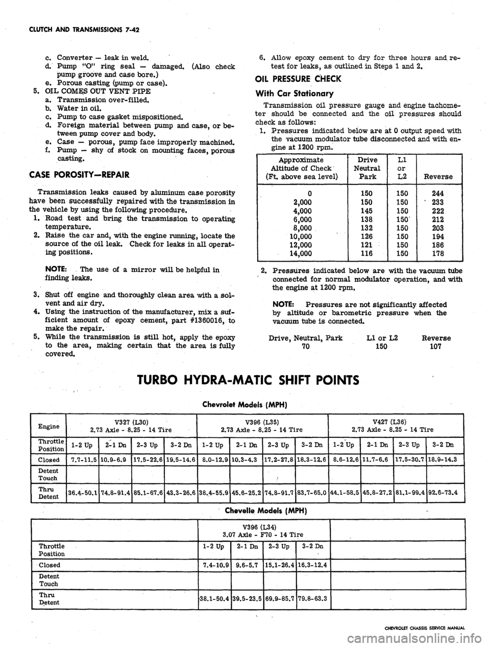
Transmission oil pressure gauge and engine tachome-
ter should be connected and the oil pressures should
check as follows:
1.
Pressures indicated below are at 0 output speed with
the vacuum modulator tube disconnected and with en-
gine at 1200 rpm.
Approximate
Altitude of Check
(Ft. above sea level)
0
2,000
4,000
6,000
8,000
10,000
12,000
14,000
Drive
Neutral
Park
150
150
145
138
132
126
121
116
LI
or
L2
150
150
150
150'
150
150
150
150
Reverse
244
233
222
212
203
194
186
178
2.
Pressures indicated below are with the vacuum tube
connected for normal modulator operation, and with
the engine at 1200 rpm.
NOTE:
Pressures are not significantly affected
by altitude or barometric pressure when the
vacuum tube is connected.
Drive, Neutral, Park Ll or L2 Reverse
70 150 107
TURBO HYDRA-MATIC SHIFT POINTS
Engine
Throttle
Position
Closed
Detent
Touch
Thru
Detent
V327 (L30)
2.73 Axle - 8.25 - 14 Tire
•1-2 Up
7.7-11.5
36.4-50.1
2-1 Dn
10.9-6.9
74.8-91.4
2-3 Up
17.5-22.6
85.1-67.6
3-2 Dn
19.5-14.6
43.3-26.6
Chevrolet Models
(MPH)
V396 (L35)
2.73 Axle - 8.25 - 14 Tire
1-2 Up
8.0-12.9
38.4-55.9
2-1 Dn
10.3-4.3
45.6-25.2
2-3 Up
17.2-27.8
/
74.8-91.7
3-2 Dn
18.3-12.6
83.7-65.0
V427 (L36)
2.73 Axle - 8.25 - 14 Tire
1-2 Up
8.6-12,6
44.1-58.5
2-1 Dn
1-1.7-6.6
45.8-27.2
2-3 Up
17.5-30.7
81.1-99.4
3-2 Dn
18.9-14.3
92.6-73.4
Chevelle Models (MPH)
Throttle
Position
Closed
Detent
Touch
Thru
Detent
V396(L34)
3.07 Axle - F70 - 14 Tire
1-2 Up
7.4-10.9
38.1-50.4
2-1 Dn
9.6-5.7
39.5-23.5
2-3 Up
15.1-26.4
69.9-85.7
3-2 Dn
16.3-12.4
79.8-63.3
CHEVROLET CHASSIS SERVICE MANUAL
Page 402 of 659
CLUTCH AND TRANSMISSIONS 7-43
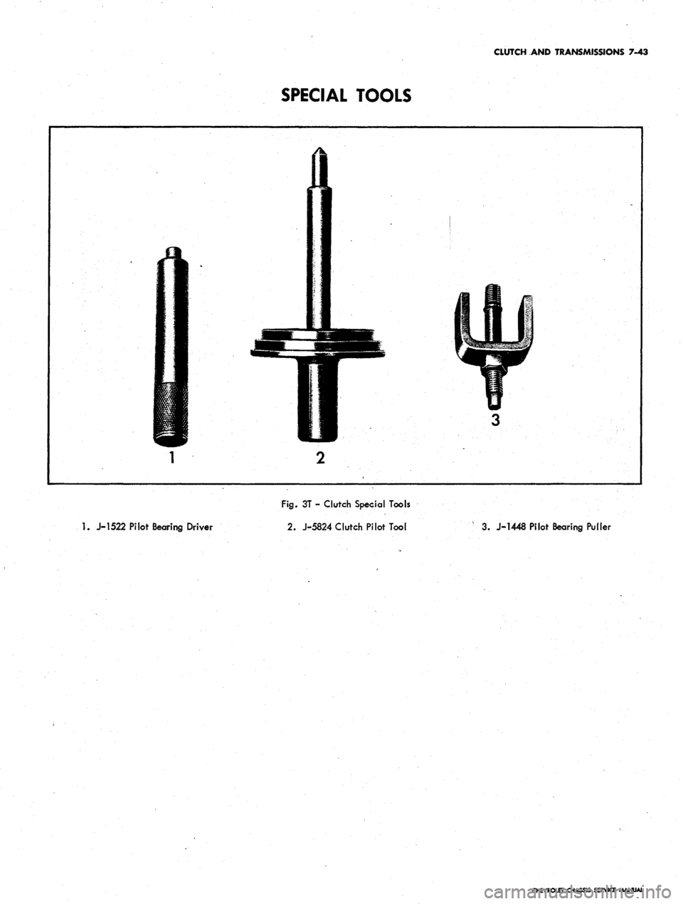
SPECIAL TOOLS
1.
J-1522 Pilot Bearing Driver
Fig.
3T - Clutch Special Tools
2.
J-5824 Clutch Pilot Tool
3. J-1448 Pilot Bearing Puller
CHEVROLET CHASSIS SERVICE MANUAL
Page 403 of 659
CLUTCH AND TRANSMISSIONS 7-44
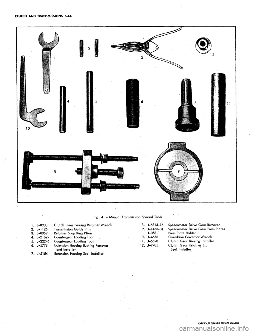
Fig.
4T - Manual Transmission Special Tools
1.
J-0933 Clutch Gear Bearing Retainer Wrench
2.
J-1126 Transmission Guide Pins
3. J-8059 Retainer Snap Ring Pliers
4.
J-21629 Countergear Loading Tool
5. J-22246 Countergear Loading Tool
6. J-5778 Extension Housing Bushing Remover
and Installer
7. J-5154 Extension Housing Seal Installer
8. J-5814-15
9. J-1453-01
J-358-1
10.
J-4653
11.
J-5590
12.
J-7785
Speedometer Drive Gear Remover
Speedometer Drive Gear Press Plates
Press Plate Holder
Overdrive Governor Wrench
Clutch Gear Bearing Installer
Clutch Gear Retainer Lip
Seal Installer
CHEVROLET CHASSIS SERVICE MANUAL
Page 404 of 659

CLUTCH AND TRANSMISSIONS 7-45
23
Fig.
5T - Aluminum Powerglide Special Tools
1. J-9506
2.
J-3289-01
3.
J-9549
4.
J-21867
5.
J-4264
6. J-3387
7.
J-9539
8. J-6839
9. J-9546
10.
J-7782
11.
J-5133
12.
J-4599
13.
J-9542
14.
J-9557
Holding Fixture Adapters
Holding Fixture (Use with J-3289-20 Base)
Converter Safety Strap
Transmission Pressure Gauge and Hose
Oil Filler Tube and Funnel
Pilot Stud Set
Front Pump Puller Bolts (Use with weights
from Slide Hammers J-6585)
Front Pump Seal Driver
Clutch Drum Bushing Remover and Installer
Clutch Spring Compressor Adapter Plate
Clutch Spring Compressor
Planet Pinion Assembly Tool Set
Reverse Piston Spring Compressor
Transmission Case Rear Bushing Remover and
Installer and Rear Pump Bushing Remover
15.
J-7079
16.
J-6582
17.
J-9543
18.
J-5778
19.
J-5154
20.
J-5403
21.
J-5814
22.
J-5853
23.
J-8039
24.
J-21848
J-8001
J-5492
J-6585
J-6585-3
J-9534
Handle
Rear Pump Bushing Installer
Vacuum
Modu
lator Wrench
Extension Bushing Remover and Installer
Extension Oil Seal Installer
Snap Ring Pliers
Speedometer Drive Gear Remover and
Installer
Torque Wrench
Snap Ring Pliers
Low Band Adjusting Tool
Dial Indicator (Not Illustrated)
Dial Indicator Support Strap (Not Illustrated)
Slide Hammers (Not Illustrated)
Slide Hammer Adapters (Not Illustrated)
Bushing Remover (Not Illustrated)
CHEVROLET CHASSIS SERVICE MANUAL
Page 405 of 659
CLUTCH AND TRANSMISSIONS 7-46
17 18 19 20 21 22
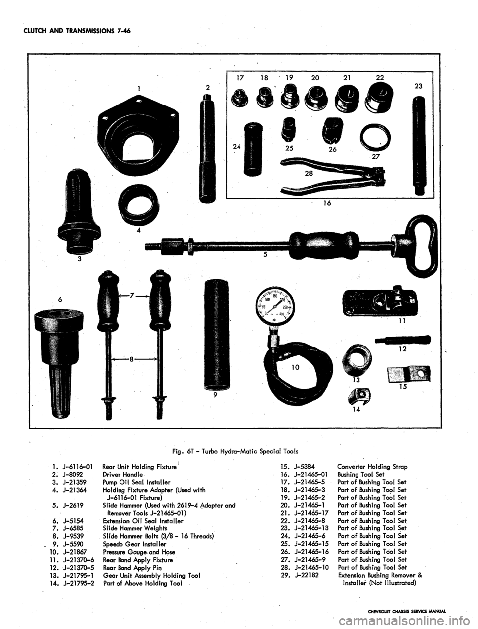
Fig.
6T - Turbo Hydra-Matic Special Tools
1.
J-6116-01
2.
J-8092
3. J-21359
4.
J-21364
5. J-2619
6. J-5154
7. J-6585
8. J-9539
9.
J-5590
10.
J-21867
11.
J-21370-6
12.
J-21370-5
13.
J-21795-1
14.
J-21795-2
Rear Unit Holding Fixture
Driver Handle
Pump Oil Seal Installer
Holding Fixture Adapter (Used with
J-6116-01 Fixture)
Slide Hammer (Used with 2619-4 Adapter and
Remover Tools J-21465-01)
Extension Oil Seal Installer
Slide Hammer Weights
Slide Hammer Bolts (3/8 - 16 Threads)
Speedo Gear Installer
Pressure Gauge and Hose
Rear Band Apply Fixture
Rear Band Apply Pin
Gear Unit Assembly Holding Tool
Part of Above Holding Tool
]5. J-5384
16.
J-21465-01
17.
J-21465-5
18.
J-21465-3
19.
J-21465-2
20.
J-21465-1
21.
J-21465-17
22.
J-21465-8
23.
J-21465-13
24.
J-2.1465-6
25.
J-21465-15
26.
J-21465-16
27.
J-21465-9
28.
J-21465-10
29.
J-22182
Converter Holding Strap
Bushing Tool Set
Part of Bushing Tool Set
Part of Bushing Tool Set
Part of Bushing Tool Set
Part of Bushing Tool Set
Part of Bushing Tool Set
Part of Bushing Tool Set
Part of Bushing Tool Set
Part of Bushing Tool Set
Part of Bushing Tool Set
Part of Bushing Tool Set
Part of Bushing Tool Set
Part of Bushing Tool Set
Extension Bushing Remover &
Installer (Not Illustrated)
CHEVROLET CHASSIS SERVICE MANUAL
Page 406 of 659
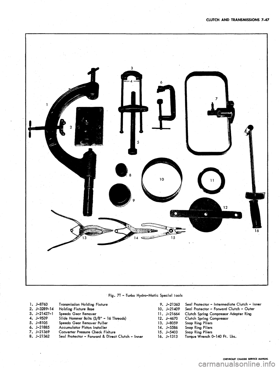
CLUTCH AND TRANSMISSIONS 7-47
Fig.
7T - Turbo Hydro-Matic Special lools
1;
J-8763
2.
J-3289-14
3. J-21427-1
4.
J-9539
5. J-8105
6. J-21885
7. J-21369
8. J-21362
Transmission Holding Fixture
Holding Fixture Base
Speedo Gear Remover
Slide Hammer Bolts (3/8" - 16 Threads)
Speedo Gear Remover Puller
Accumulator Piston Installer
Converter Pressure Check Fixture
Seal Protector - Forward & Direct Clutch - Inner
9. J-21363
10.
J-21409
11.
J-21664
12.
J-4670
13.
J-8059
14.
J-5586
15.
J-5403
16.
J-1313
Seal Protector - Intermediate Clutch - Inner
Seal Protector - Forward Clutch - Outer
Clutch Spring Compressor Adapter Ring
Clutch Spring Compressor
Snap Ring Pliers
Snap Ring Pliers
Snap Ring Pliers
Torque Wrench 0-140 Ft. Lbs.
CHEVROLET CHASSIS SERVICE MANUAL
Page 407 of 659
SECTION 8
FUEL TANK AND EXHAUST SYSTEMS
CONTENTS OF THIS SECTION
Page
Chevrolet .. . . 8-1
Fuel Tanks 8-1
Exhaust Systems 8-5
Chevelle 8-8
Fuel Tanks 8-8
Exhaust Systems 8-11
Chevy n ...... 8-13
Fuel Tanks 8-13
Page
Exhaust Systems 8-16
Corvette 8-18
Fuel Tanks 8-18
Exhaust Systems 8-24
Camaro 8-26
Fuel Tank 8-26
Exhaust System 8-30
Special Tools 8-33
CHEVROLET
FUEL TANKS
INDEX
Page
Page
General Description
Component Part Replacement
Fuel Tank
8-1 Fuel Lines 8-3
8-2 Fuel Tank Vent Lines 8-4
8-2 Metering Units (Gauge Sending Unit ) 8-4
GENERAL DESCRIPTION
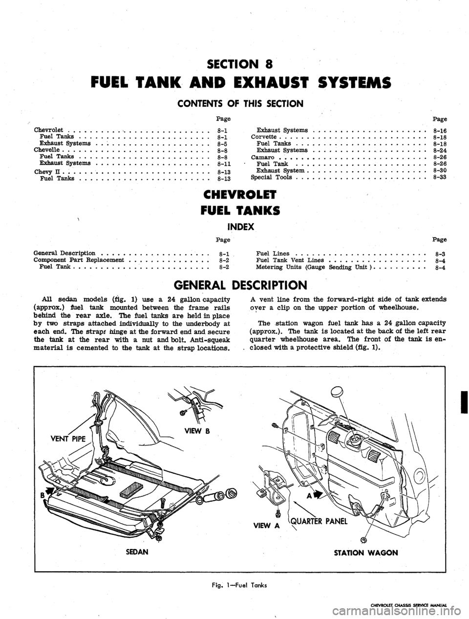
All Sedan models (fig. 1) use a 24 gallon capacity
(approx.) fuel tank mounted between the frame rails
behind the rear axle. The fuel tanks are held in place
by two straps attached individually to the underbody at
each end. The strap? hinge at the forward end and secure
the tank at the rear with a nut and bolt. Anti-squeak
material is cemented to the tank at the strap locations.
A vent line from the forward-right side of tank extends
over a clip on the upper portion of wheelhouse.
The station wagon fuel tank has a 24 gallon capacity
(approx.). The tank is located at the back of the left rear
quarter wheelhouse area. The front of the tank is en-
closed with a protective shield (fig. 1).
VIEW A ^QUARTER PANEL
SEDAN
STATION WAGON
I
Fig.
1-Fuel
Tanks
CHEVROLET CHASSIS SERVICE MANUAL
Page 408 of 659
FUEL TANK AND EXHAUST SYSTEMS 8-2
COMPONENT PART REPLACEMENT
FUEL TANK
Draining Tank
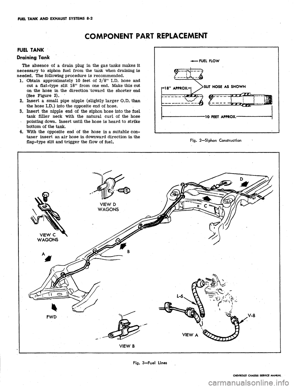
The absence of a drain plug in the gas tanks makes it
necessary to siphon fuel from the tank when draining is
needed. The following procedure is recommended.
1.
Obtain approximately 10 feet of 3/8" I.D. hose and
cut a flat-type slit 18" from one end. Make this cut
on the hose in the direction "toward the shorter end
(See Figure 2).
2.
Insert a small pipe nipple (slightly larger O.D. than
the hose I.D.) into the opposite end of hose.
3.
Insert the nipple end of the siphon hose into the fuel
tank filler neck with the natural curl of the hose
pointing down. Insert until the hose is heard to strike
bottom of the tank.
4.
With the opposite end of the hose in a suitable con-
taner insert an air hose in downward direction in the
flap-type slit and trigger the flow of fuel.
FUEL FLOW
-If*
APPROX.-1 >SUT «<>«
AS SHOWN
10 FEET APPROX.-
Fig. 2—Siphon Construction
FWD
V-8
VIEW B
Fig. 3-Fuel Lines
CHEVROLET CHASSIS SERVICE MANUAL
Page 409 of 659
FUEL TANK AND EXHAUST SYSTEMS 8-3
CAUTION: Always drain gasoline from com-
plete fuel system including carburetor, fuel
pump and all fuel lines and fuel tank if the vehi-
cle is to be stored for any appreciable length of
time. This precaution will prevent accumulation
of gum formation and resultant poor engine
performance.
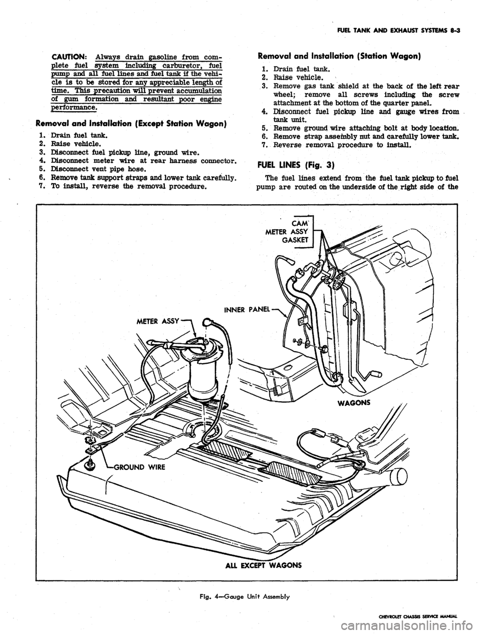
Removal and Installation (Except Station Wagon)
1.
Drain fuel tank.
2.
Raise vehicle.
3.
Disconnect fuel pickup line, ground wire.
4.
Disconnect meter wire at rear harness connector.
5. Disconnect vent pipe hose.
6. Remove tank support straps and lower tank carefully.
7. To install, reverse the removal procedure.
Removal and Installation (Station Wagon)
1.
Drain fuel tank.
2.
Raise vehicle.
3.
Remove gas tank shield at the back of the left rear
wheel; remove all screws including the screw
attachment at the bottom of the quarter panel.
4.
Disconnect fuel pickup line and gauge wires from
tank unit.
5. Remove ground wire attaching bolt at body location.
6. Remove strap assembly nut and carefully lower tank.
7. Reverse removal procedure to install.
FUEL LINES (Fig. 3)
The fuel lines extend from the fuel tank pickup to fuel
pump are routed on the underside of the right side of the
CAM
METER ASSY
GASKET
METER ASSY
ALL EXCEPT WAGONS
Fig.
4—Gauge Unit Assembly
CHEVROLET CHASSIS SERVICE MANUAL
Page 410 of 659
FUEL TANK AND EXHAUST SYSTEMS 8-4
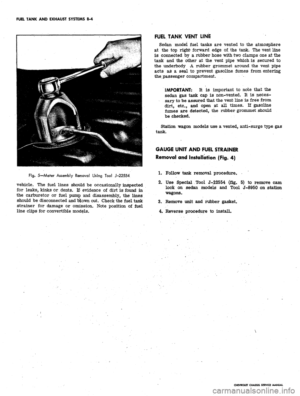
Fig.
5— Meter Assembly Removal Using Tool J-22554
vehicle. The fuel lines should be occasionally inspected
for leaks, kinks or dents. If evidence of dirt is found in
the carburetor or fuel pumto and disassembly, the lines
should be disconnected
and
blown out. Check the fuel tank
strainer for damage or omission. Note position of fuel
line clips for convertible models.
FUEL TANK VENT LINE
Sedan modei fuel tanks are vented to the atmosphere
at the top right- forward edge of. the tank. The vent line
is connected by a rubber hose with two clamps one at the
tank and the other at the vent pipe which is secured to
the underbody A rubber grommet around the vent pipe
acts as a seal to prevent gasoline fumes from entering
the.passenger compartment.
IMPORTANT: It is important to note that the
sedan gas tank cap is non-vented. It is neces-
sary to be assured that the vent line is free from
dirt, etc., and open at all times. If gasoline
fumes are detected, the rubber grommet should
be checked.
Station wagon models use a vented, anti-surge type gas
tank.
GAUGE UNIT AND FUEL STRAINER
Removal and Installation (Fig. 4)
1.
Follow tank removal procedure.
2.
Use Special Tool J-22554 (fig. 5) to remove cam
lock on sedan models and Tool J-8950 on station
wagons.
3.
Remove unit and rubber gasket.
4.
Reverse procedure to install.
CHEVROLET CHASSIS SERVICE MANUAL