coil CHEVROLET CAMARO 1967 1.G Chassis Service Manual
[x] Cancel search | Manufacturer: CHEVROLET, Model Year: 1967, Model line: CAMARO, Model: CHEVROLET CAMARO 1967 1.GPages: 659, PDF Size: 114.24 MB
Page 319 of 659
ENGINE FUEL 6M-11
dripping fuel, but a leak on the suction would not be ap-
parent except for its effect of reducing volume of fuel on
the pressure side.
1.
Tighten any loose line connections and look for bends
or kinks in lines.
2.
Disconnect fuel pipe at carburetor. Disconnect dis-
tributor to coil primary wire so that engine can be
cranked without firing. Place suitable container at
end of pipe and crank engine a few revolutions. If
little or no gasoline flows from open end of pipe then
fuel pipe is clogged or pump is inoperative. Before
removing pump disconnect fuel pipe at gas tank and
outlet pipe and blow through them with an air hose
to make sure they are clear. Reconnect pipes and
retest while cranking engine.
CAUTION: Whenever the engine is cranked re-
motely at the starter, with a special jumper
cable or other means, the primary distributor
lead must be disconnected from the negative
post on the coil and the ignition switch must be
in the "ON" position. Failure to do this will
result in a damaged grounding circuit in the
ignition switch.
3.
If fuel flows from pump in good volume from pipe
at carburetor, check fuel delivery pressure to be
certain that pump is operating withint specified limits
as follows:
a. Attach a fuel pump pressure test gauge to dis-
connect end of pump to carburetor pipe.
b.
Run engine at approximately 450-1,000 rpm (on
gasoline in carburetor bowl) and note reading on
pressure gauge.
c. If pump is operating properly the pressure will
be within specifications and will remain constant
at speeds between 450-1,000 rpm. If pressure
is too low, too high, or varies materially at dif-
ferent speeds, the pump should be replaced.
Removal
1.
Disconnect fuel inlet and outlet pipes at fuel pump.
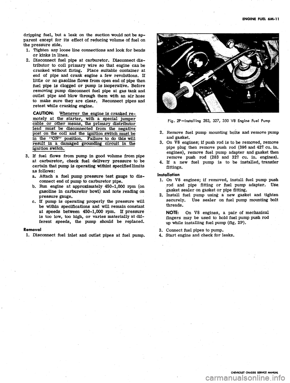
Fig.
2P-Installing 283, 327, 350 V8 Engine Fuel Pump
2.
Remove fuel pump mounting bolts and remove pump
and gasket.
3.
On V8 engines; if push rod is to be removed, remove
pipe plug then remove push rod (396 and 427 cu. in.
engines), remove fuel pump adapter and gasket then
remove push rod (283 and 327 cu. in. engines).
4.
If a new fuel pump is to be installed, transfer
fittings.
Installation
1.
On V8 engines; if removed, install fuel pump push
rod and pipe fitting or fuel pump adapter. Use.
gasket sealer on gasket or pipe fitting.
2.
Install fuel pump using a new gasket and tighten
securely. Use sealer on fuel pump mounting bolt
threads.
NOTE:
On V8 engines, a pair of mechanical
fingers may be used to hold fuel pump push rod
up while installing fuel pump (fig. 2P).
3.
Connect fuel pipes to pump.
4.
Start engine and check for leaks.
CHEVROLET CHASSIS SERVICE MANUAL
Page 332 of 659
ENGINE-ELECTRICAL 6Y-7
CHARGING SYSTEM
INDEX
Page
General Description . 6Y-7
Maintenance and Adjustments 6Y-9
Static Checks . 6Y-10
System Condition Check and Voltage
•Regular Adjustment. 6Y-10
General Output 6Y-11
Generator Diode and Field Test 6Y-12
Indicator Lamp-Initial Field Excitation
Circuit Tests . 6Y-12
Page
Field Circuit Resistance Wire Tests 6Y-13
Field Relay Test and Adjustment 6Y-14
Other Harness Checks 6Y-14
Service Operations 6Y-14
Generator 6Y-14
Removal and Installation 6Y-14
Pulley Replacement. 6Y-14
Brush Replacement (6" Delcotron). 6Y-15
Double Contact Regulator . . . . . . 6Y-16
GENERAL DESCRIPTION
The charging system includes the battery, generator,
regulator, telltale light, and necessary wiring to connect
these components. The Delcotron is offered as standard
equipment, although there are various capacities avail-
able on all models.
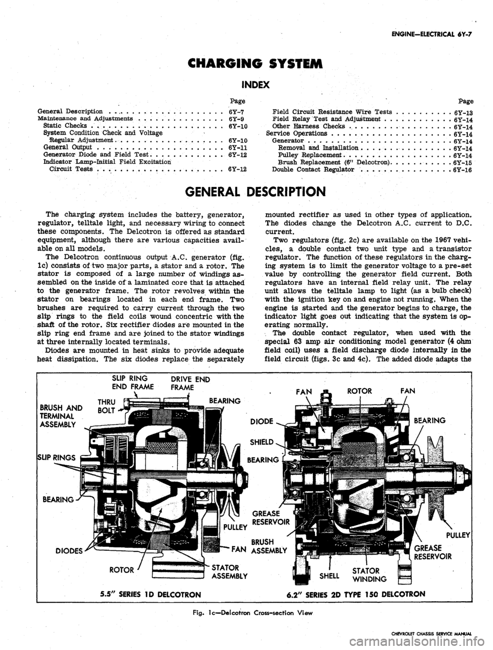
The Delcotron continuous output A.C. generator (fig.
lc) consists of two major parts, a stator and a rotor. The
stator is composed of a large number of windings as-
sembled on the inside of a laminated core that is attached
to the generator frame. The rotor revolves within the
stator on bearings located in each end frame. Two
brushes are required to carry current through the two
slip rings to the field coils wound concentric with the
shaft of the rotor. Six rectifier diodes are mounted in the
slip ring end frame and are joined to the stator windings
at three internally located terminals.
Diodes are mounted in heat sinks to provide adequate
heat dissipation. The six diodes replace the separately
mounted rectifier as used in other types of application.
The diodes change the Delcotron A.C. current to D.C.
current.
Two regulators (fig. 2c) are available on the 1967 vehi-
cles,
a double contact two unit type and a transistor
regulator. The function of these regulators in the charg-
ing system is to limit the generator voltage to a pre-set
value by controlling the generator field current. Both
regulators have an internal field relay unit. The relay
unit allows the telltale lamp to light (as a bulb check)
with the ignition key on and engine not running. When the
engine is started and the generator begins to charge, the
indicator light goes out indicating that the system is op-
erating normally.
The double contact regulator, when used with the
special 63 amp air conditioning model generator (4 ohm
field coil) uses a field discharge diode internally in the
field circuit (figs. 3c and 4c). The added diode adapts the
BRUSH AND
TERMINAL
ASSEMBLY
SLIP RINGS
SLIP RING
END FRAME
_\
THRU
BOLT
DRIVE END
FRAME
BEARING
BEARING
DIODES
ROTOR
5.5" SERIES ID DELCOTRON
STATOR
ASSEMBLY
GREASE
RESERVOIR
BRUSH
FAN ASSEMBLY
6.2" SERIES 2D TYPE 150 DELCOTRON
Fig.
lc—Delcotron Cross-section View
CHEVROLET CHASSIS SERVICE MANUAL
Page 333 of 659
ENGINE-ELECTRICAL 6Y-8
1
FIELD RELAY^I^p2
"LATCH"
^PFN?^
"P1
TERMINAL
JyJvJCTl^
NO. 2 TERMINAD^5^^^«
NO.
3 TERMINAL ^S5«£
NO.
4 TERMINAL ^^^
m
# / VOLTAGE
¥ REGULATOR
1
ACCESS PLUG TO
VOLTAGE ADJUSTMENT
No 4 TERMINAL
Double Contact
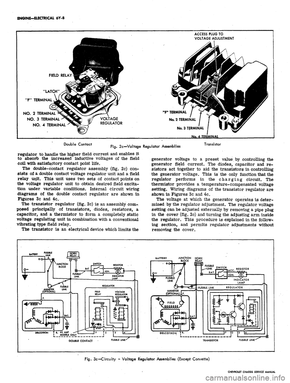
Fig.
2c—Voltage Regulator Assemblies
Transistor
regulator to handle the higher field current and enables it
to absorb the increased inductive voltages of the field
coil with satisfactory contact point life.
The double-contact regulator assembly (fig. 2c) con-
sists of a double contact voltage regulator unit and a field
relay unit. This unit uses two sets of contact points on
the voltage regulator unit to obtain desired field excita-
tion under variable conditions. Internal circuit wiring
diagrams of the double contact regulator are shown in
Figures 3c and 4c.
The transistor regulator (fig. 2c) is an assembly com-
posed principally of transistors, diodes, resistors, a
capacitor, and a thermistor to form a completely static
voltage regulating unit in combination with a conventional
vibrating type field relay.
The transistor is an electrical device which limits the
generator voltage to a preset value by controlling the
generator field current. The diodes, capacitor and re-
sistors act together to aid the transistors in controlling
the generator voltage. This is the only function that the
regulator performs in the charging circuit. The
thermistor provides a temperature-compensated voltage
setting. Wiring diagrams of the transistor regulator are
shown in Figures 3c and 4c.
The voltage at which the generator operates is deter-
mined by the regulator adjustment. The regulator voltage
setting can be adjusted externally by removing a pipe plug
in the cover (fig. 2c) and turning the adjusting arm inside
the regulator. This procedure is explained in the followr
ing section, and permits regulator adjustments without
removing the cover.
FUSIBLE
DOUBLE CONTACT
FUSIBLE LINK-^
JUNCTION HORN
BLOCK RELAY
RESISTOR
Q FIELD Q>
DELCOTRON TR-
TRANSISTOR
FUSIBLE LINK-
Fig.
3c-Circuity - Voltage Regulator Assemblies (Except Corvette)
CHEVROLET CHASSIS SERVICE MANUAL
Page 339 of 659
ENGINE-ELECTRICAL 6Y-14
VOLTMETER
WIRING HARNESS
CONNECTOR
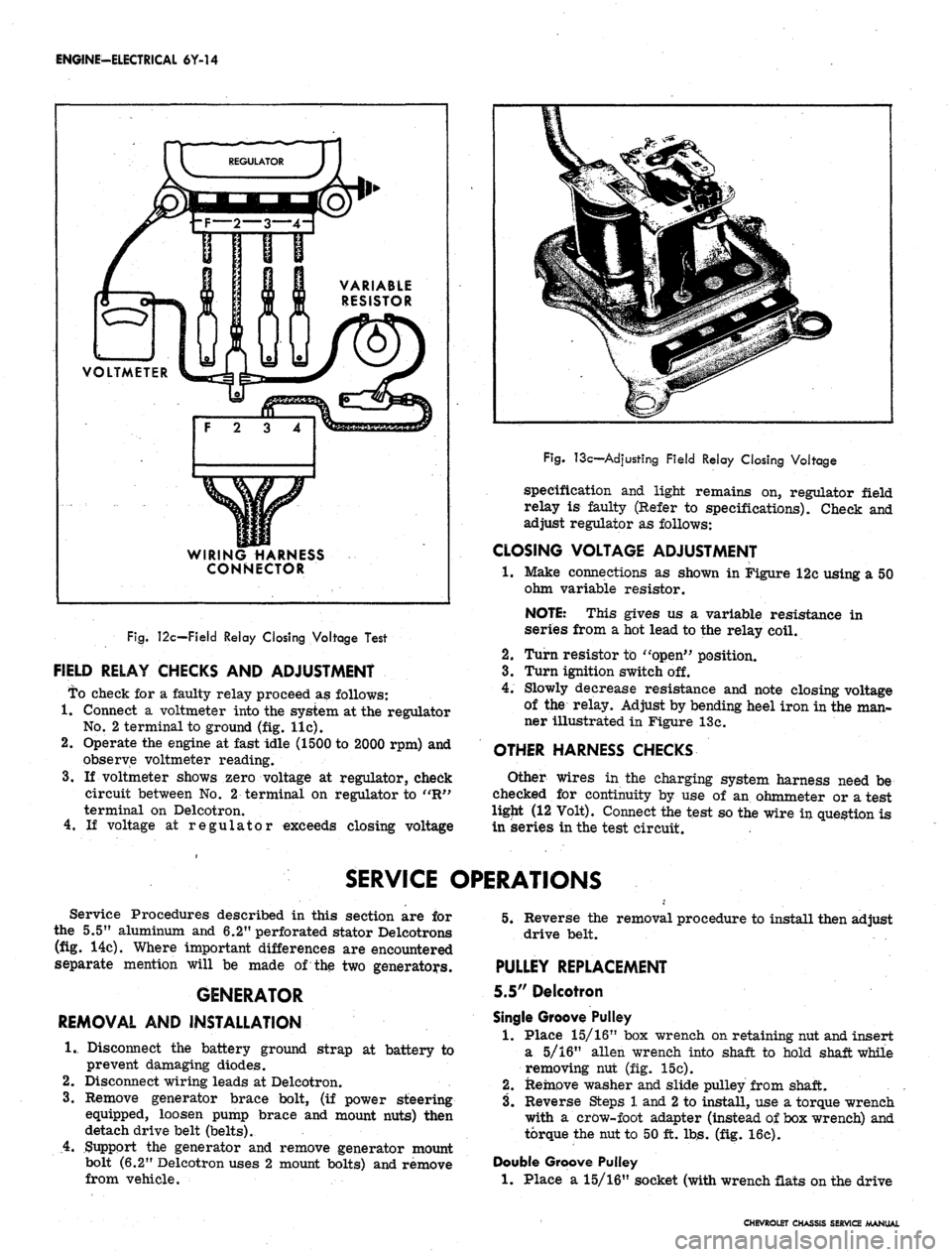
Fig.
12c—Field Relay Closing Voltage Test
FIELD RELAY CHECKS AND ADJUSTMENT
To check for a faulty relay proceed as follows:
1.
Connect a voltmeter into the system at the regulator
No.
2 terminal to ground (fig. lie).
2.
Operate the engine at fast idle (1500 to 2000 rpm) and
observe voltmeter reading.
3.
If voltmeter shows zero voltage at regulator, check
circuit between No. 2 terminal on regulator to "R"
terminal on Delcotron.
4.
If voltage at regulator exceeds closing voltage
Fig.
13c—Adjusting Field Relay Closing Voltage
specification and light remains on, regulator field
relay is faulty (Refer to specifications). Check and
adjust regulator as follows:
CLOSING VOLTAGE ADJUSTMENT
•1.
Make connections as shown in Figure 12c using a 50
ohm variable resistor.
NOTE: This gives us a variable resistance in
series from a hot lead to the relay coil.
2.
Turn resistor to "open" position.
3.
Turn ignition switch off.
4.
Slowly decrease resistance and note closing voltage
of the relay. Adjust by bending heel iron in the man-
ner illustrated in Figure 13c.
OTHER HARNESS CHECKS
Other wires in the charging system harness need be
checked for continuity by use of an ohmmeter or a test
ligjit (12 Volt). Connect the test so the wire in question is
in series in the test circuit.
SERVICE OPERATIONS
Service Procedures described in this section are for
the 5.5" aluminum and 6.2" perforated stator Delcotrons
(fig. 14c). Where important differences are encountered
separate mention will be made of the two generators.
GENERATOR
REMOVAL AND INSTALLATION
1.
Disconnect the battery ground strap at battery to
prevent damaging diodes.
2.
Disconnect wiring leads at Delcotron.
3.
Remove generator brace bolt, (if power steering
equipped, loosen pump brace and mount nuts) then
detach drive belt (belts).
4.
Support the generator and remove generator mount
bolt (6.2" Delcotron uses 2 mount bolts) and remove
from vehicle.
5.
Reverse the removal procedure to install then adjust
drive belt.
PULLEY REPLACEMENT
5.5" Delcotron
Single Groove Pulley
1.
Place 15/16" box wrench on retaining nut and insert
a 5/16" alien wrench into shaft to hold shaft while
removing nut (fig. 15c).
2.
Remove washer and slide pulley from shaft.
3.
Reverse Steps 1 and
2
to install, use a torque wrench
with a crow-foot adapter (instead of box wrench) and
torque the nut to 50 ft. lbs. (fig. 16c).
Double Groove Pulley
1.
Place a 15/16" socket (with wrench flats on the drive
CHEVROLET CHASSIS SERVICE MANUAL
Page 343 of 659
ENGINE-ELECTRICAL 6Y-18
IGNITION SYSTEMS
INDEX
Page
General Description . 6Y-18
Maintenance and Adjustments 6Y-19
Breaker Point System 6Y-19
Breakerless System . . 6Y-X9
Ignition Coil Check 6Y-19
Spark Plugs 6Y-19
Service Operations , 6Y-19
Distributor Contact Points . 6Y-19
Cleaning 6Y-19
Replacement 6Y-20
Setting Dwell Angle 6Y-21
Distributor Condenser 6Y-22
Performance Diagnosis. 6Y-22
Replacement . . 6Y-23
Distributor
Breaker Point Type 6Y-23
Removal. . 6Y-23
Disassembly • 6Y-23
Page
Cleaning and Inspection .....'.., 6Y-25
Assembly . 6Y-25
Installation 6Y-26
Breakerless i 6Y-27
Removal . 6Y-27
Disassembly and Assembly 6Y-27
Installation 6Y-27
Off-Engine Test. . 6Y-27
Coil Replacement 6Y-27
Pulse Amplifier. 6Y-28
Disassembly .6Y-4S8
Component Checks
!
6Y-28
Assembly 6Y-29
Ignition Switch Replacement 6Y-29
Spark Plugs 6Y-30
Cleaning and Regapping I ....... 6Y-30
Installation . 6Y-31
GENERAL DESCRIPTION
There are two ignition systems available on 1967
vehicles. The breaker point type which is continued as
the regular production system and the optional (Corvette
only) transistor controlled breakerless ignition system
(magnetic pulse type). The transistor ignition system
features a specially designed distributor, control unit
(ignition pulse amplifier), and a special coil. Two resist-
ance wires are also used in the circuit; one as a ballast
between the coil negative terminal and ground, while the
other resistance wire provides a voltage drop for the
engine run circuit and is by-passed at cranking. The
other units in the system (the ignition switch, spark
plugs,
and battery) are of standard design. The dis-
tributor and control unit (ignition pulse amplifier) are
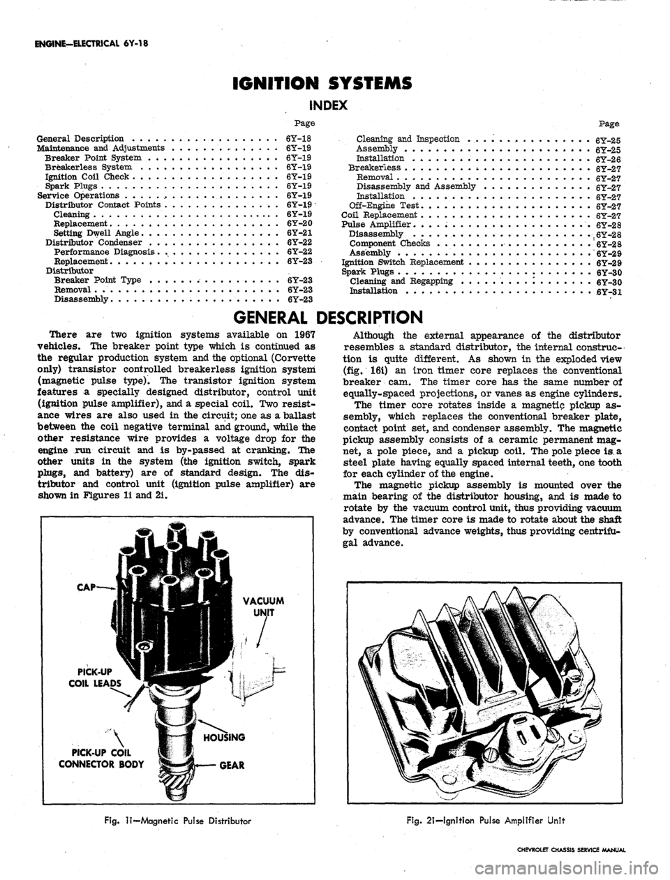
shown in Figures li and 2i.
CAP-
VACUUM
PICK-UP
COIL LEADS
PICK-UP COIL
CONNECTOR BODY
Although the external appearance of the distributor
resembles a standard distributor, the internal construc-
tion is quite different. As shown in the exploded view
(fig. 16i) an iron timer core replaces the conventional
breaker cam. The timer core has the same number of
equally-spaced projections, or vanes as engine cylinders.
The timer core rotates inside a magnetic pickup as-
sembly, which replaces the conventional breaker plate,
contact point set, and condenser assembly. The magnetic
pickup assembly consists of a ceramic permanent mag-
net, a pole piece, and a pickup coil. The pole piece
is.
a
steel plate having equally spaced internal teeth, one tooth
for each cylinder of the engine.
The magnetic pickup assembly is mounted over the
main bearing of the distributor housing, and is made to
rotate by the vacuum control unit, thus providing vacuum
advance. The timer core is made to rotate about the shaft
by conventional advance weights, thus providing centrifu-
gal advance.
Fig.
li—
Magnetic Pulse Distributor
Fig.
2i-lgnition Pulse Amplifier Unit
CHEVROLET CHASSIS SERVICE MANUAL
Page 344 of 659
MAINTENANCE AND ADJUSTMENTS
ENGINE-ELECTRICAL 6Y-19
PERIODIC MAINTENANCE
BREAKER POINT SYSTEM
The distributor breaker points and spark plugs are the
only ignition system components that require periodic
service. The remainder of the ignition system requires
only periodic inspection to check operation of the units,
tightness of the electrical connections, and condition of
the wiring. When checking the coil, test with a reputable
tester.
Breaker type distributors are equipped with cam lubri-
cator and should have the wick replaced at the same time
contact point set is replaced. It is not necessary to
lubricate the breaker cam when using a cam lubricator.
Do not attempt to lubricate the wick - Replace when
necessary. When installing a new wick, adjust its posi-
tion so the end of the wick just touches the lobe of the
breaker cam.
Distributor shaft lubrication is accomplished by a
reservoir of lube around the mainshaft in the distributor
body.
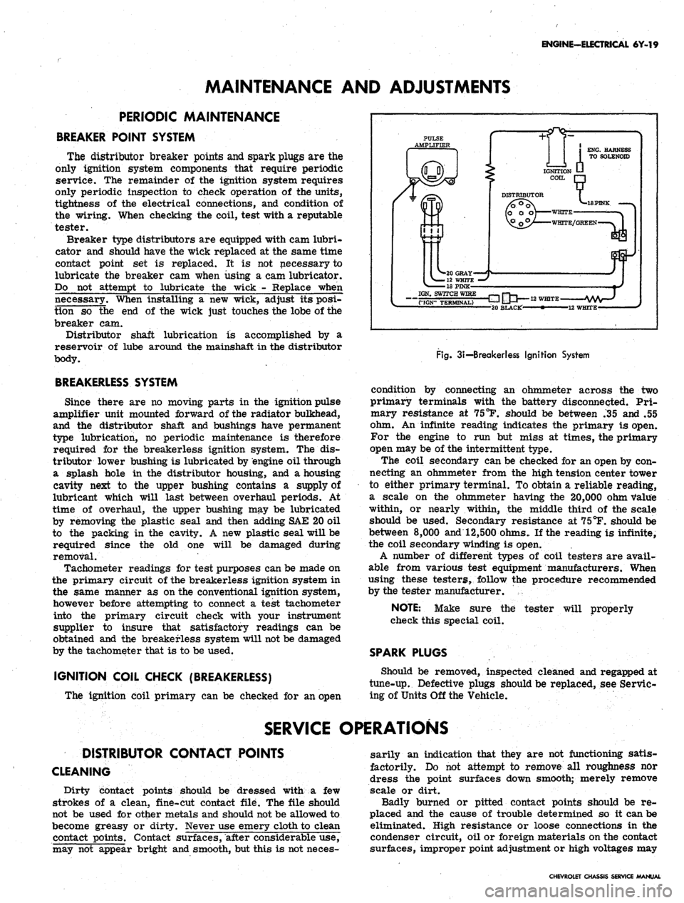
BREAKERLESS SYSTEM
Since there are no moving parts in the ignition pulse
amplifier unit mounted forward of the radiator bulkhead,
and the distributor shaft and bushings have permanent
type lubrication, no periodic maintenance is therefore
required for the breakerless ignition system. The dis-
tributor lower bushing is lubricated by engine oil through
a splash hole in the distributor housing, and a housing
cavity next to the upper bushing contains a supply of
lubricant which will last between overhaul periods. At
time of overhaul, the upper bushing may be lubricated
by removing the plastic seal and then adding SAE 20 oil
to the packing in the cavity. A new plastic seal will be
required since the old one will be damaged during
removal.
Tachometer readings for test purposes can be made on
the primary circuit of the breakerless ignition system in
the same manner as on the conventional ignition system,
however before attempting to connect a test tachometer
into the primary circuit check with your instrument
supplier to insure that satisfactory readings can be
obtained and the breakerless system will not be damaged
by the tachometer that is to be used,
IGNITION COIL CHECK (BREAKERLESS)
The ignition coil primary can be checked for an open
PULSE
AMPLIFIER
IGN. SWITCH WIRE
"("IGN" TERMINAL)
-E3 IJU
12
WHITE-
-20 BLACKf' • 12 WHITE-
Fig.
3i—
Breakerless Ignition System
condition by connecting an ohmmeter across the two
primary terminals with the battery disconnected. Pri-
mary resistance at 75
°F.
should be between .35 and .55
ohm. An infinite reading indicates the primary is open.
For the engine to run but miss at times, the primary
open may be of the intermittent type.
The coil secondary can be checked for an open by con-
necting an ohmmeter from the high tension center tower
to either primary terminal. To obtain a reliable reading,
a scale on the ohmmeter having the 20,000 ohm value
within, or nearly within, the middle third of the scale
should be used. Secondary resistance at 75°F. should be
between
8,000
and 12,500 ohms. If the reading is infinite,
the coil secondary winding is open.
A number of different types of coil testers are avail-
able from various test equipment manufacturers. When
using these testers, follow the procedure recommended
by the tester manufacturer.
tester will properly
NOTE:
Make sure the
check this special coil.
SPARK PLUGS
Should be removed, inspected cleaned and regapped at
tune-up. Defective plugs should be replaced, see Servic-
ing of Units Off the Vehicle.
SERVICE OPERATIONS
DISTRIBUTOR CONTACT POINTS
CLEANING
Dirty contact points should be dressed with a few
strokes of a clean, fine-cut contact file. The file should
not be used for other metals and should not be allowed to
become greasy or dirty. Never use emery cloth to clean
contact points. Contact surfaces, after considerable use,
may not appear bright and smooth, but this is not neces-
sarily an indication that they are not functioning satis-
factorily. Do not attempt to remove all roughness nor
dress the point surfaces down smooth; merely remove
scale or dirt.
Badly burned or pitted contact points should be re-
placed and the cause of trouble determined so it can be
eliminated. High resistance or loose connections in the
condenser circuit, oil or foreign materials on the contact
surfaces, improper point adjustment or high voltages may
CHEVROLET CHASSIS SERVICE MANUAL
Page 348 of 659
ENGINE-ELECTRICAL 6Y-23
condenser leak or to a defective connection. This
will cause burned points and ignition failure upon
initial starts and at high speeds.
4.
Capacity - Capacity is determined by the area of
the metallic elements and the insulating and im-
pregnating materials.
For a complete check of the condenser, use a tester
which will check for all of the above conditions. Follow
the instructions given by the manufacturer of the
test equipment. Condenser capacity should be
.18-:
23
microfarads.
REPLACEMENT
Four and Six Cylinder Engine Distributor (Fig. 4i)
1.
Release distributor cap hold-down screws, remove
cap and place it out of the work area.
2.
Remove rotor.
3.
Disconnect condenser lead wire from contact point
quick-disconnect terminal.
4.
Remove condenser attaching screw, lift.condenser
from breaker plate and wipe breaker plate clean.
5. Install new condenser using reverse of procedure
outlined above.
Eight Cylinder Engine Distributor
1.
Remove distributor cap.
2.
Loosen condenser lead attaching screw (fig. 6i) and
lift out condenser lead clip.
3.
Remove screw holding condenser bracket to breaker
plate and slide condenser from bracket.
4.
To replace condenser reverse the above procedure.
NOTE:
Make sure that new condenser lead is
installed in proper position (fig. 6i).
DISTRIBUTOR
(BREAKER POINT TYPE)
REMOVAL
1.
On radio equipped Corvettes, remove ignition shield
from over distributor and coil. One bolt is accessible
from top of shield, the other two are at rear of
shield, facing firewall.
2.
Release the distributor cap hold-down screws, re-
move the cap and place it clear of the work area.
NOTE:
If necessary, remove secondary leads
from the distributor cap after first marking the
cap tower for the lead to No. 1 cylinder. This
will aid in the reinstallation of leads in the cap.
3.
Disconnect the distributor primary lead from the coil
terminal.
4.
Scribe a realignment mark on the distributor bowl
and engine in line with the rotor segment.
5. Disconnect vacuum line to distributor and tachometer
drive cable (Corvette). Remove the distributor hold-
down bolt and elamp and remove the distributor from
the engine. Note position of vacuum advance mecha-
nism relative to the engine.
CAUTION: Avoid rotating the engine with the
distributor removed as the ignition timing will
be upset.
Rg.
121-L-6 Distributor-Exploded View
1.
Breaker Plate Attaching
Screws
2.
Condenser Attaching
Screws
3. Condenser
4.
Breaker Plate Assembly
4a.
Cam Lubricator
5. Vacuum Control Assembly
6. Vacuum Control
Attaching Screws
7. Housing
8. Cap
9. Rotor
DISASSEMBLY
10.
Contact Point
Attaching Screw
11.
Contact Point Assembly
12.
Weight Cover
Attaching Screws
13.
Weight Cover
14.
Weight Springs
15.
Advance Weights
16. Cam Assembly
17.
Main Shaft Assembly
18.
Roll Pin
19.
Drive Gear
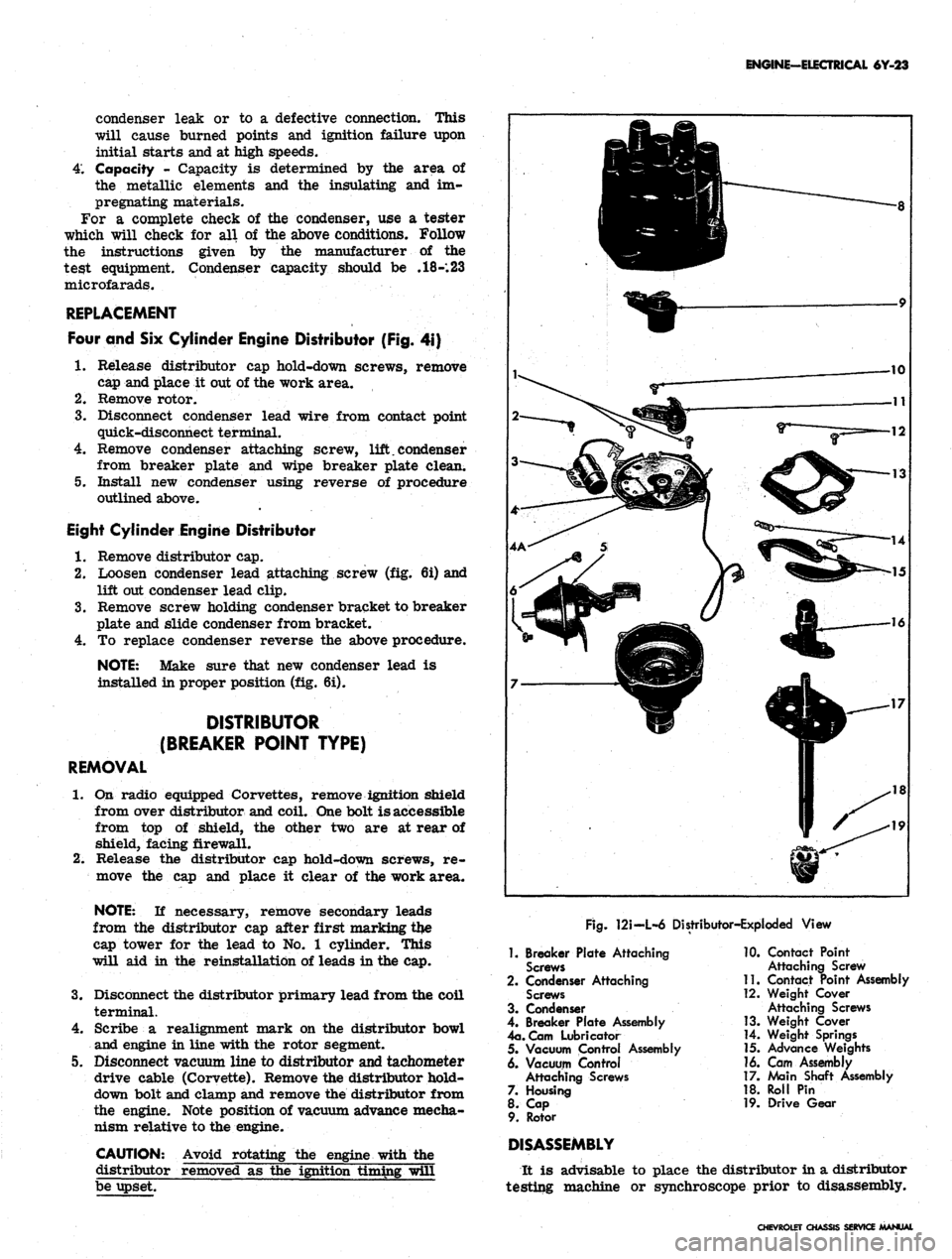
It is advisable to place the distributor in a distributor
testing machine or synchroscope prior to disassembly.
CHEVROLET CU
SERVICE MANUAL
Page 351 of 659
ENGINE-ELECTRICAL 6Y-26
INSTALLATION-ENGINE NOT DISTURBED
(ALL MODELS)
1.
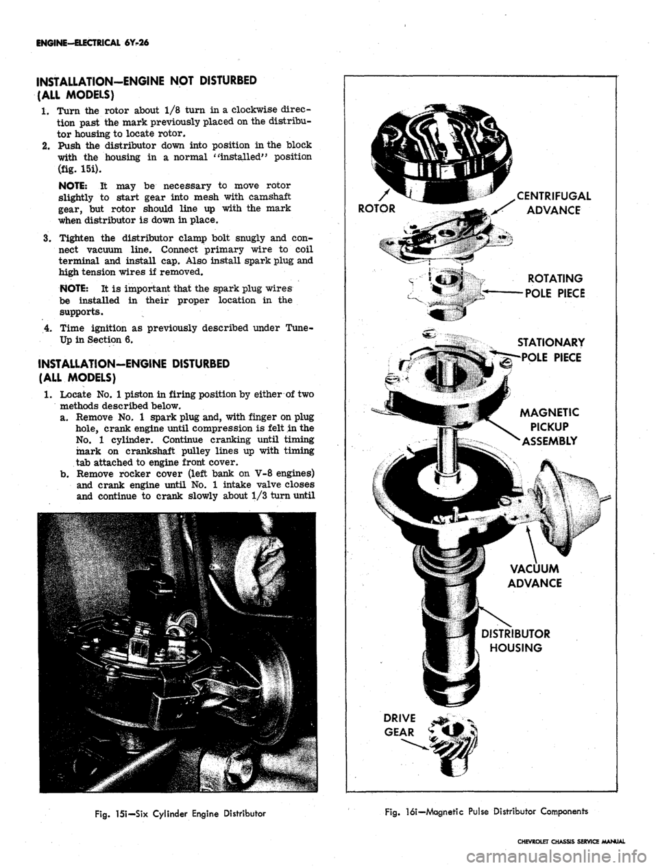
Turn the rotor about 1/8 turn in a clockwise direc-
tion past the mark previously placed on the distribu-
tor housing to locate rotor.
2.
Push the distributor down into position in the block
with the housing in a normal "installed" position
(fig. 15i).
NOTE: It may be necessary to move rotor
slightly to start gear into mesh with camshaft
gear, but rotor should line up with the mark
when distributor is down in place.
3.
Tighten the distributor clamp bolt snugly and con-
nect vacuum line. Connect primary wire to coil
terminal and install cap. Also install spark plug and
high tension wires if removed.
NOTE: It is important that the spark plug wires
be installed in their proper location in the
supports.
4.
Time ignition as previously described under Tune-
Up in Section 6.
INSTALLATION-ENGINE DISTURBED
(ALL MODELS)
1.
Locate No. 1 piston in firing position by either of two
methods described below,
a. Remove No. 1 spark plug and, with finger on plug
hole,
crank engine until compression is felt in the
No.
1 cylinder. Continue cranking until timing
mark on crankshaft pulley lines up with timing
tab attached to engine front cover.
b.
Remove rocker cover (left bank on V-8 engines)
and crank engine until No. 1 intake valve closes
and continue to crank slowly about 1/3 turn until
CENTRIFUGAL
jS ADVANCE
ROTATING
POLE PIECE
STATIONARY
POLE PIECE
MAGNETIC
PICKUP
ASSEMBLY
VACUUM
ADVANCE
DISTRIBUTOR
HOUSING
Fig.
151—Six Cylinder Engine Distributor
Fig.
16i—Magnetic Pulse Distributor Components
CHEVROLET CHASSIS SERVICE MANUAL
Page 352 of 659
ENGINE-ELECTRICAL 6Y-27
timing mark on pulley lines up with timing tab.
2.
Position distributor to opening in block in normal
installed attitude (fig. 15i), noting position of vacuum
control unit.
3.
Position rotor to point toward front of engine (with
distributor housing held in installed attitude), then
turn rotor counter-clockwise approximately 1/8 turn
more toward left cylinder bank and push distributor
down to engine camshaft. It may be necessary to ro-
tate rotor slightly until camshaft engagement is felt.
4.
While pressing firmly down on distributor housing,
kick starter over a few times to make sure oil pump
shaft is engaged. Install hold-down clamp and bolt
and snug up bolt.
5. Turn distributor body slightly until points just open
and tighten distributor clamp bolt.
6. Place distributor cap in position and check to see
that rotor lines up with terminal for No. 1 spark
plug.
7. Install cap, check all high tension wire connections
and connect spark plug wires if they have been re-
moved. It is important that the wires be installed in
their location in the supports.
NOTE:
The brackets are numbered to show the
correct installation. Wires must be installed as
indicated to prevent cross firing.
8. Connect vacuum line to distributor and distributor
primary wire to coil terminal.
9. Start engine and set timing as described under Turn-
Up in Section 6.
BREAKERLESS (MAGNETIC PULSE)
DISTRIBUTOR
REMOVAL (CORVETTE)
1.
If vehicle is equipped with radio, remove three bolts
securing ignition shield over distributor and coil.
One bolt is accessible from the top of shield, the
other two are at rear of shield, facing firewall.
2.
Disconnect tachometer drive cables from distributor
housing.
3.
Disconnect pickup coil leads at connector.
4.
Remove distributor cap.
5. Crank engine so rotor is in position to fire No. 1
cylinder and timing mark on harmonic balancer is
indexed with pointer.
6. Remove vacuum line from distributor.
7. Remove distributor clamping screw and hold-down
clamp.
8. Remove distributor and distributor-to-block gasket.
It will be noted that the rotor will rotate as the
distributor is pulled out of the block. Mark the re-
lationship of the rotor and the distributor housing
after removal so that the rotor can be set in the
same position when the distributor is being installed.
DISASSEMBLY (Fig. 16i)
NOTE:
If a distributor is being disassembled
for replacement of the stationary magnetic
pickup assembly only, it will be necessary to
perform only Steps 3, 4, 5, 7, 8, 9, and 12 of the
service procedure listed below.
1.
Remove screws securing rotor and remove rotor.
2.
Remove centrifugal weight springs and weights.
3.
Remove the tachometer drive gear from the distribu-
tor (Corvette only).
4.
Remove roll pin, then remove distributor drive gear
and washer.
CAUTION: To prevent
magnet, support drive gear
;e to the permanent
?n
driving out roll
pin.
5. Remove drive shaft assembly.
6. Remove centrifugal weight support and timer core
from drive shaft.
7. Remove connector from pickup coil leads.
8. Remove retaining ring which secures magnetic
core support plate to distributor shaft bushing in
housing.
9. As a unit, remove the entire magnetic pickup assem-
bly from the distributor housing.
10.
Remove brass washer and felt pad.
11.
Remove vacuum advance unit.
12.
To reassemble distributor, perform the above steps
in reverse order.
INSTALLATION (CORVETTE)
1.
Check to see that the engine is at firing position for
No.
1 cylinder (timing mark on harmonic balancer
indexed with pointer).
2.
Position a new distributor-to-block gasket on the
block.
3.
Before installing distributor, index rotor with hous-
ing as noted when distributor was removed. Install
distributor in block so that vacuum diaphragm faces
approximately 45° forward on the right side of the
engine and the rotor points toward contact in cap for
No.
1 cylinder.
4.
Replace distributor clamp leaving screw loose
enough to allow distributor to be turned for timing
adjustment.
5. Install spark plug wires in distributor cap. Place
wire for No. 1 cylinder in tower (marked on old cap
during disassembly) then install remaining wires
clockwise around the cap according to the firing
order (1-8-4-3-6-5-7-2).
6. Attach distributor to coil primary wires.
7. Replace distributor cap.
8. Adjust timing and then fully tighten distributor clamp
screw.
9. Attach vacuum line to distributor.
10.
Connect tachometer drive cables to distributor body.
11.
Replace ignition shields.
DISTRIBUTOR OFF-ENGINE TEST
The distributor's centrifugal and vacuum advance can
be checked in a distributor testing machine or synchro-
scope specially adapted or designed to accommodate this
type distributor. However, since this involves removing
the distributor from the engine, this test may be post-
poned until other system checks have been made. A dwell
reading cannot be obtained on this distributor and it is not
likely that the centrifugal or vacuum advance will be a
cause of trouble.
COIL REPLACEMENT
1.
Disconnect ignition switch and distributor leads from
CHEVROLET CHASSIS SERVICE MANUAL
Page 353 of 659

ENGINE-ELECTRICAL 6Y-28
terminals on eoil. On Corvettes equipped with radio,
remove bolts securing ignition shield over distribu-
tor and coil.
2.
Pull high tension wire from center terminal of coil.
3.
Remove the two coil support mounting bolts or loosen
friction clamp screw and remove coil.
4.
Place new coil in position and install attaching bolts
or tighten clamp screw.
5.
Place high tension lead securely in center terminal
of coil and connect ignition switch and distributor
primary leads to terminals on coil. Replace ignition
shield on Corvettes.
6. Start engine and test coil operation.
IGNITION PULSE AMPLIFIER
DISASSEMBLY
To check the amplifier for defective components, pro-
ceed as follows:
1.
Remove the bottom plate from the amplifier.
2.
To aid in reassembly, note the locations of the lead
connections to the panel board.
3.
Remove the three panel board attaching screws, and
lift the assembly from the housing.
4.
To aid in reassembly, note any identifying markings
on the two transistors and their respective locations
on the panel board and heat sink assembly.
5.
Note the insulators between the transistors.and the
heat sink, and the insulators separating the heat sink
from the panel board.
6. Remove the transistor attaching screws, and sepa-
rate the two transistors and heat sink from the panel
board.
7.
Carefully examine the panel board for evidence of
damage.
MOUNTING
SCREW
RESISTOR R5 jgSfe. / DIODE Dl
TRANSISTOR TR2
(UNDERNEATH)
1H L >©V
[So
To
I
/'%**jt\
\
TRANSISTC>R"""
1 X ^^w^ X \ (UNDERNEATH)
9^ESISTORR^^^H|^^^^^H
^B
RESISTOR
R4
^HPH^^H
WM'
RESISTOR
R3
I^B^^^^I^U
N .6 ®
mm
N%|/MOUNTING
• tr^i^w ^\ vjR SCREW
CAPACITOR
Cl\
pNkj^^A^
\
RESISTOR
Rl
MOUNTING ^55S^^ \ CAPACITOR C3
SCREW I RESISTOR R6 CAPACITOR C2
TRANSISTOR TR3
COMPONENT CHECKS (Figs. \7\ and 18i)
With the two transistors separated from the assembly,
an ohmmeter may be used to check the transistors and
components on the panel board for defects. An ohmmeter
having a 1-1/2 volt cell, which is the type usually found
in service stations, is recommended. The low range
scale on the ohmmeter should be used except where
specified otherwise.
A 25 watt soldering gun is recommended, and a 60% tin
40%
lead solder should be used when re-soldering. Avoid
excessive heat which may damage the panel board. Chip
away any epoxy involved, and apply new epoxy which is
commercially available.
In order to check the panel board assembly, it is
necessary to unsolder at the locations indicated in Fig-
ure 18i the two capacitors C2 and C3. In all of the fol-
lowing checks, connect the ohmmeter as shown and then
reverse the ohmmeter leads to obtain two readings. The
amplifier circuitry is shown in Figure 19i.
1.
Transistors TR1 and TR2: Check each transistor by
referring to Figure 20i. If both readings in Step 1
are zero, the transistor is shorted. If both readings
in Step 2 are zero, the transistor is shorted; and if
both readings are infinite, the transistor is open.
Interpret Step 3 the same as Step 2.
2.
Trigger Transistor TR3:
11
both readings in Step 1
are zero, the transistor is shorted. If both readings
in Step 2 are zero, the transistor is shorted; and if
both readings are infinite, the transistor is open.
Interpret Step 3 the same as Step 2.
3.
Diode Dl: 11 both readings are zero, the diode is
shorted; and if both readings are infinite, the diode
is open.
4.
Capacitor Cl: If both readings are zero, the capaci-
tor is shorted.
5.
Capacitors C2 and C3: Connect the ohmmeter across
CHECKING
RESISTOR Rl
UNSOLDER
I
CHECKING TRIGGER
TRANSISTOR TR3
CHECKING
CAPACITOR C
Fig.
171—Pulse Amplifier Panel Board
Fig.
18i—Pulse
Amplifier
Component
Checks
CHEVROLET CHASSIS SERVICE MANUAL