coil CHEVROLET CAMARO 1967 1.G Chassis Owner's Manual
[x] Cancel search | Manufacturer: CHEVROLET, Model Year: 1967, Model line: CAMARO, Model: CHEVROLET CAMARO 1967 1.GPages: 659, PDF Size: 114.24 MB
Page 197 of 659
REAR SUSPENSION AND DRIVE LINE 4-7
tioned vertically in the torque arm before ap-
plying pressure to the puller screw.
5.
Remove shim and bearing spacer from spindle
support.
6. Note size of shim used. If dial indicator reading
was more than
.008",
select a shim thinner by the
amount needed to bring end play within limits. If
dial indicator reading was less than
.001",
select a
shim thicker by the amount needed to bring end play
within limits.
NOTE: Shims are available in thicknesses from
.097"
to .148" in increments of
.003".
EXAMPLE: Bearing end play reading obtained
on dial indicator was
.011",
.003" over limit.
Bearing shim removed from spindle measures
.145".
New shim installed measures .139", .006"
smaller. End play is now decreased by .006" and
is
.005",
which is within the .001" to .008" limit.
7.
After determining shim thickness, install bearing
spacer and shim on spindle. Position spindle in
spindle support.
8. Press inner bearing race and roller assembly on
spindle as follows.
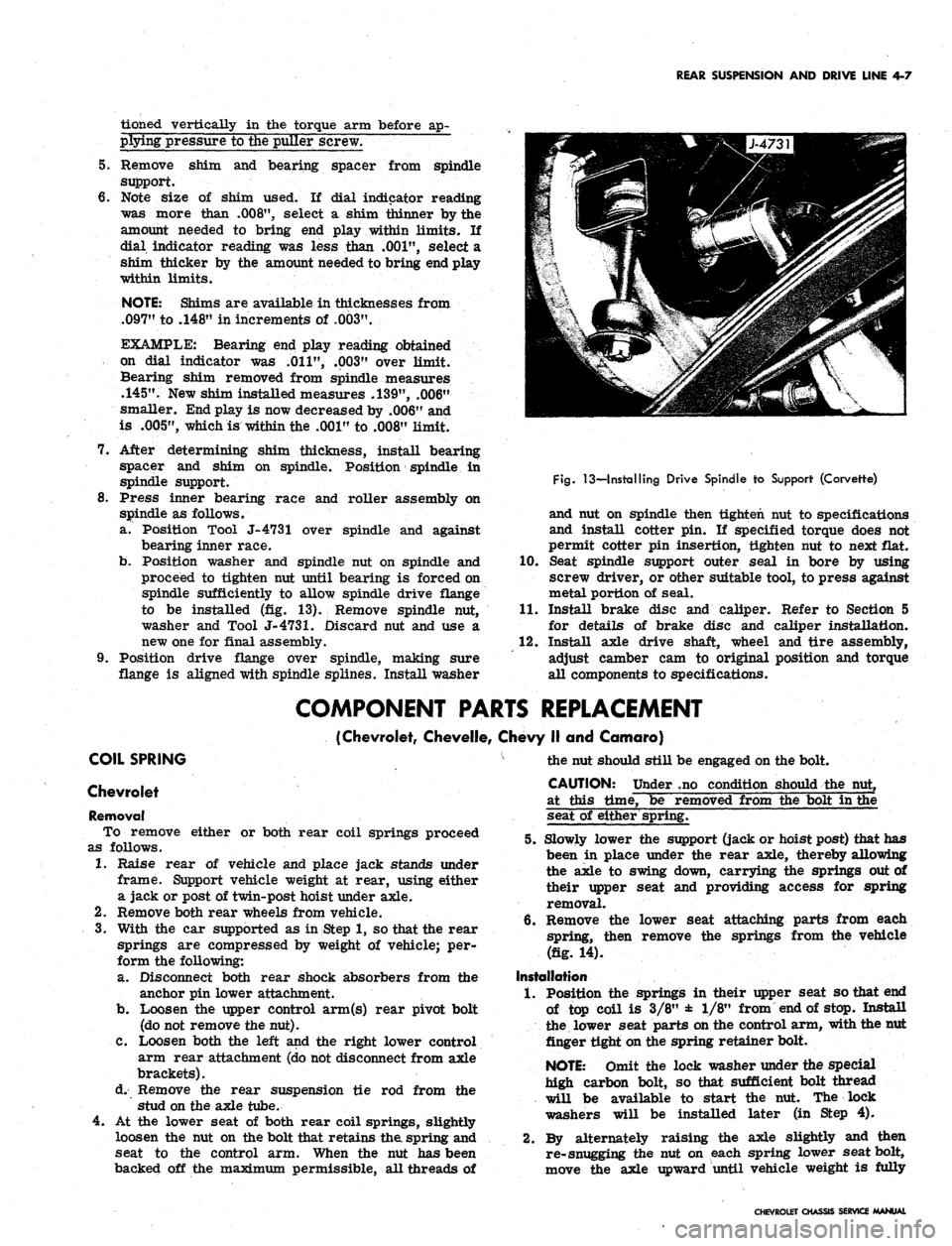
a. Position Tool J-4731 over spindle and against
bearing inner race.
b.
Position washer and spindle nut on spindle and
proceed to tighten nut until bearing is forced on
spindle sufficiently to allow spindle drive flange
to be installed (fig. 13). Remove spindle nut,
washer and Tool
J-4731.
Discard nut and use a
new one for final assembly.
9. Position drive flange over spindle, making sure
flange is aligned with spindle splines. Install washer
Fig.
13—Installing Drive Spindle to Support (Corvette)
and nut on spindle then tighten nut to specifications
and install cotter pin. If specified torque does not
permit cotter pin insertion, tighten nut to next flat.
10.
Seat spindle support outer seal in bore by using
screw driver, or other suitable tool, to press against
metal portion of seal.
11.
Install brake disc and caliper. Refer to Section 5
for details of brake disc and caliper installation.
12.
Install axle drive shaft, wheel and tire assembly,
adjust camber cam to original position and torque
all components to specifications.
COMPONENT PARTS REPLACEMENT
(Chevrolet, Chevelle, Chevy II and Camaro)
COIL SPRING
Chevrolet
Removal
To remove either or both rear coil springs proceed
as follows.
1.
Raise rear of vehicle and place jack stands under
frame. Support vehicle weight at rear, using either
a jack or post of twin-post hoist under axle.
2.
Remove both rear wheels from vehicle.
3.
With the car supported as in Step 1, so that the rear
springs are compressed by weight of vehicle; per-
form the following:
a. Disconnect both rear shock absorbers from the
anchor pin lower attachment.
b.
Loosen the upper control arm(s) rear pivot bolt
(do not remove the nut).
C. Loosen both the left and the right lower control
arm rear attachment (do not disconnect from axle
brackets).
d. Remove the rear suspension tie rod from the
stud on the axle tube.
4.
At the lower seat of both rear coil springs, slightly
loosen the nut on the bolt that retains the spring and
seat to the control arm. When the nut has been
backed off the maximum permissible, all threads of
the nut should still be engaged on the bolt.
CAUTION: Under ,no condition should the nut,
at this time, be removed from the bolt in the
seat of either spring.
5.
Slowly lower the support (jack or hoist post) that has
been in place under the rear axle, thereby allowing
the axle to swing down, carrying the springs out of
their upper seat and providing access for spring
removal.
6. Remove the lower seat attaching parts from each
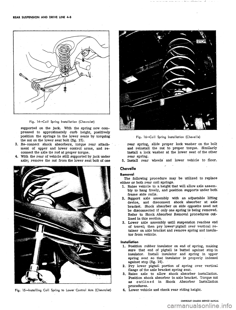
spring, then remove the springs from the vehicle
(fig. 14).
Installation
1.
Position the springs in their upper seat so that end
of top coil is 3/8" ± 1/8" from end of stop. Install
the lower seat parts on the control arm, with the nut
finger tight on the spring retainer bolt.
NOTE: Omit the lock washer under the special
high carbon bolt, so that sufficient bolt thread
will be available to start the nut. The lock
washers will be installed later (in Step 4).
2.
By alternately raising the axle slightly and then
re-snugging the nut on each spring lower seat bolt,
move the axle upward until vehicle weight is fully
CHEVROLET CHASSIS SERVICE MANUAL
Page 198 of 659
REAR SUSPENSION AND DRIVE LINE 4-8
Fig.
14—Coil Spring Installation (Chevrolet)
supported on the jack. With the spring now com-
pressed to approximately curb height, positively
position the springs in the lower seats by torquing
the nut on the lower seat bolt (fig. 15).
Re-connect shock absorbers, torque rear attach-
ment of upper and lower control arms, and re-
connect the axle tie rod at proper torque.
With the rear of vehicle still supported by jack under
axle;
remove the nut from the lower seat bolt of one
Fig.
15—Installing Coil Spring to Lower Control Arm (Chevrolet)
Fig.
16—Coil Spring Installation (Chevelle)
rear spring, slide proper lock washer on the bolt
and reinstall the nut to proper torque. Similarly
install a lock washer at the lower seat of the other
rear spring.
5.
Install rear wheels and lower vehicle to floor.
Chevelle
Removal
The following procedure may be utilized to replace
either or both rear coil springs.
1.
Raise vehicle to a height that will allow axle assem-
bly to hang freely, and position supports under both
frame side rails.
2.
Support axle assembly with an adjustable lifting
device, and disconnect shock absorber at axle
bracket. Shock absorber on side opposite need not
be disconnected if only one spring is being removed.
Refer to Shock Absorber Removal procedures out-
lined in this section.
3.
Lower axle assembly until suspension reaches end
of travel; then pry lower% pigtail over vertical re-
tainer on axle bracket and remove spring and insula-
tor from vehicle.
Installation
1.
Position rubber insulator on end of spring, making
sure that end of pigtail is butted against stop in
insulator. Install insulator and spring in upper
spring seat so that insulator is properly indexed
against stop (fig. 16).
2.
Pry lower pigtail portion of spring over vertical
flange of the axle bracket spring seat.
3.
Raise axle to allow shock absorber installation.
Position shock absorber in axle bracket. Torque nut
as outlined in Shock Absorber Installation
procedures.
4.
Lower vehicle and check rear riding height.
CHEVROLET CHASSIS SERVICE MANUAL
Page 205 of 659
REAR SUSPENSION AND DRIVE LINE 4-15
ship of parts, then install Spacer J-
7574-
3 over
the partially installed bushing and between the
sides of the control arm.
f. Continue to tighten J-
21058-
8
until bushing is
pulled flush against control arm. Do not exert
undue force against control arm after bushing is
installed. Overtightening of J-21058-
8
will cause
damage to walls of control arm.
g. Disassemble tools and inspect bushing for proper
installation.
Replace the rear bushing as follows:
a. Position Puller Screw J-21058-8 through Re-
mover Adapter J-21830-2 so that head of screw
is opposite button end of remover. Install this
assembly, threaded end of sc'rew first, through
bushing to be removed.
b.
Install Receiver J-21830-4 and Bridge J-21830-7
. over screw and against control arm. Position
thrust bearing against J-21830-7 and screw
J-21058-8 snugly against bearing. Install Spacer
J-
2183d-
3
between sides of control arm and over
bushing.
c. Check tool installation for proper alignment and
tighten J-21058-8 to withdraw bushing from con-
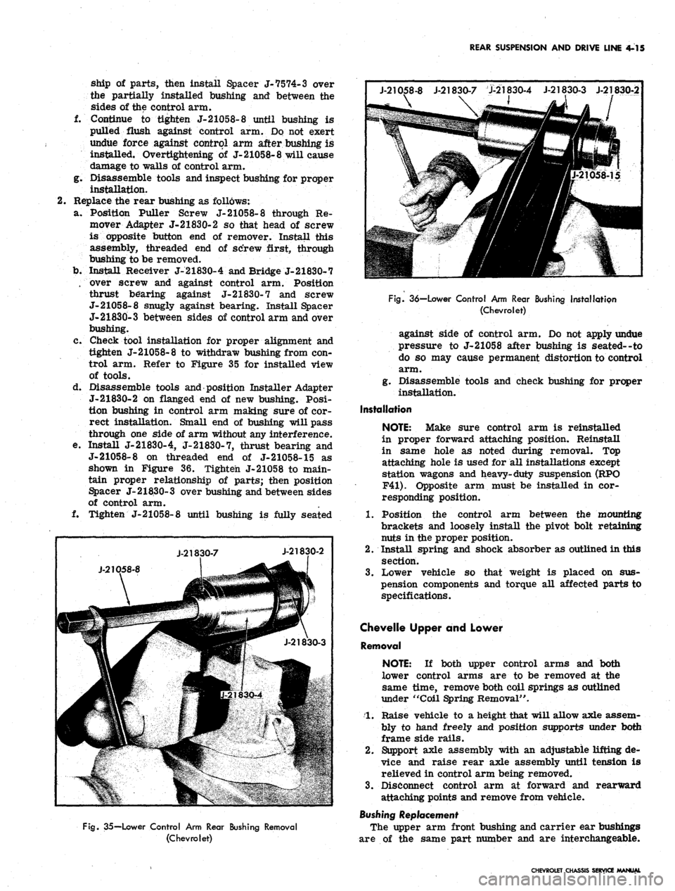
trol arm. Refer to Figure 35 for installed view
of tools.
d. Disassemble tools and position Installer Adapter
J-21830-2 on flanged end of new bushing. Posi-
tion bushing in control arm making sure of cor-
rect installation. Small end of bushing will pass
through one side of arm without any interference.
e. Install J-21830-4, J-21830-7, thrust bearing and
J-21058-8 on threaded end of J-21058-15 as
shown in Figure 36. Tighten J-21058 to main-
tain proper relationship of parts; then position
Spacer J- 21830- 3 over bushing and between sides
of control arm.
f. Tighten J-21058-8 until bushing is fully seated
J-21058-8 J-21830-7 J-21830-4 J-21830-3 J-21830-2
\
J-2K
X
D58-8
J-218
30-7
IP
•he?
21830-4
J-21830-2
JfSir
J-21830-3
Fig.
35—Lower Control Arm Rear Bushing Removal
(Chevrolet)
Fig.
36—Lower Control Arm Rear Bushing Installation
(Chevrolet)
against side of control arm. Do not apply undue
pressure to J-21058 after bushing is seated--to
do so may cause permanent distortion to control
arm.
g. Disassemble tools and check bushing for proper
installation.
Installation
NOTE:
Make sure control arm is reinstalled
in proper forward attaching position. Reinstall
in same hole as noted during removal. Top
attaching hole is used for all installations except
station wagons and heavy-duty suspension (RPO
F41).
Opposite arm must be installed in cor-
responding position.
1.
Position the control arm between the mounting
brackets and loosely install the pivot bolt retaining
nuts in the proper position.
2.
Install spring and shock absorber as outlined in this
section.
3.
Lower vehicle so that weight is placed on sus-
pension components and torque all affected parts to
specifications.
Chevelle Upper and Lower
Removal
NOTE:
If both upper control arms and both
lower control arms are to be removed at the
same time, remove both coil springs as outlined
under "Coil Spring Removal".
1.
Raise vehicle to a height that will allow axle assem-
bly to hand freely and position supports under both
frame side rails.
2.
Support axle assembly with an adjustable lifting de-
vice and raise rear axle assembly until tension is
relieved in control arm being removed.
3.
Disconnect control arm at forward and rearward
attaching points and remove from vehicle.
Bushing Replacement
The upper arm front bushing and carrier ear bushings
are of the same part number and are interchangeable.
CHEVROLET CHASSIS SERVICE MANUAL
Page 220 of 659
REAR SUSPENSION AND DRIVE LINE 4-30
Fig.
76—Differential Gear Failure
Hypoid Gears
Hypoid gear tooth scoring (fig. 74) is caused generally
by improper break-in, incorrect lube, insufficient gear
backlash or improper 'ring/pinion gear alignment. The
scoring will progressively lead to complete erosion of
the gear tooth, or gear tooth pitting and eventual fracture
with possible attendant damage to bearings, if the initial
scoring condition is not diagnosed in time and corrected.
Hypoid gear scoring is easily recognized by its char-
acteristic loud whine in either drive, coast or under both
conditions. Another cause of hypoid tooth fracture (fig.
75) is extended overloading of the gear set which will
produce fatigue fracture, or shock loading which will
result in sudden failure.
Differential Gears
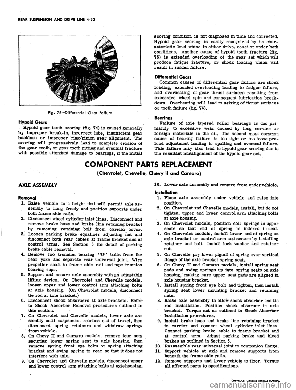
Common causes of differential gear failure are shock
loading, extended overloading leading to fatigue failure,
and overheating of gear thrust surfaces resulting from
excessive wheel spin and consequent lubrication break-
down. Overheating will lead to seizing of thrust surfaces
or tooth failure (fig. 76).
Bearings
• Failure of axle tapered roller bearings is due pri-
marily to excessive wear caused by long service or
foreign materials in the oil. The second most common
cause of bearing failure is too tight or too loose pre-
load adjustment leading to spalling and eventual failure.
This failure may also lead to hypoid gear scoring due to
the resultant misalignment of the hypoid gear set.
COMPONENT PARTS REPLACEMENT
(Chevrolet, Cheveile, Chevy II and Camaro)
AXLE ASSEMBLY
Removal
1.
Raise vehicle to a height that will permit axle as-
sembly to hang freely and position supports under
both frame side rails.
2.
Disconnect wheel cylinder inlet lines. Disconnect and
remove brake hose and brake line retaining bracket
by removing retaining bolt from carrier cover.
3.
Loosen parking brake equalizer adjusting nut and
disconnect both rear cables at frame bracket and at
control arms. See Section 5 for detail of parking
brake cable removal.
4.
Remove two trunnion bearing "U" bolts from the
rear yoke and separate rear universal joint. Wire
propeller shaft to frame side rail and tape trunnion
bearing cups.
5. Support arid secure axle assembly with an adjustable
lifting device. On Chevrolet and Cheveile models,
loosen upper and lower control arm attaching bolts
at axle housing. (On Chevrolet models, disconnect
tie rod at axle bracket.)
6. Disconnect shock absorbers at axle brackets. Refer
to Shock Absorber Removal procedures outlined in
this section.
7. On Chevrolet and Cheveile models, lower axle as-
sembly until suspension reaches end of travel, then
disconnect spring retainers and withdraw springs
from vehicle.
8. On Chevy II and Camaro models, remove four nuts
securing lower spring seat to axle housing, then
remove spring front eye bolts or spring attaching
bracket and swing spring to rear so that it does not
interfere with axle.
9. On Chevrolet and Cheveile models, disconnect upper
and lower control arm attaching bolts at axle housing*
10.
Lower axle assembly and remove from under vehicle.
Installation
1.
Place axle assembly under vehicle and raise into
position.
2.
On Chevrolet and Cheveile models, install, but do not
tighten, upper and lower control arm attaching bolts
at axle housing.
3.
On Chevrolet models, position coil springs in upper
seats so that end of spring is indexed in seat.
4.
On Chevrolet models, install lower end of spring on
axle bracket or control arm and secure by installing
retainer and bolt. Install lock washer and retainer
nut.
5. On Cheveile pry lower pigtail of spring over vertical
flange of the axle bracket spring seat.
6. On Chevy II and Camaro models, install spring seat
pads and swing springs up into spring seats on axle
housing, making sure upper seat pads are aligned in
axle housing bracket.
7. Install spring front eye bolt and tighten, then install
spring seat lower mounting bracket and retaining
nuts.
8. Raise axle assembly to allow shock absorber and tie
rod installation. Position shock absorber in axle
bracket. Torque nut as outlined in Shock Absorber
Installation procedures.
9. Install brake hose and brake line retaining bracket
to carrier and connect wheel cylinder inlet lines.
Connect parking brake cable to frame bracket and
at control arm. Adjust parking brake and bleed
brakes as outlined in Section 5.
10.
Reassemble rear universal joint to companion flange.
11.
Support vehicle at axle and remove supports from
beneath the frame side rails.
12.
Remove supports and lower vehicle to floor. Torque
all affected parts to specifications.
CHEVROLET CHASSIS SERVICE MANUAL
Page 267 of 659
ENGINE 6-2
remotely at the starter, with a special jumper
cable or other means, the primary distributor
lead must be disconnected from the negative
post on the coil and the ignition switch must be
in the "ON" position. Failure to do this will
result in a damaged grounding circuit in the
ignition switch.
3.
Crank engine through at least four compression
strokes to obtain highest possible reading.
4.
Check and record compression of each cylinder.
5.
If one or more cylinders read low tor uneven, inject
about a tablespoon of engine oil on top of pistons
in low reading cylinders (through spark plug
port).
Crank engine several times and recheck
compression.
• If compression comes up but does not necessarily
reach normal, rings are worn.
• If compression does not improve, valves are
burnt, sticking or not seating properly.
• If two adjacent cylinders indicate low compres-
sion and injecting oil does not increase compres-
sion, the cause may be a head gasket leak between
the cylinders. Engine coolant and/or oil in cylin-
ders could result from this defect.
NOTE: If a weak cylinder cannot be located
with the compression check, see "Cylinder Bal-
ance Test" under "Additional Checks and Adjust-
ments" in this section.
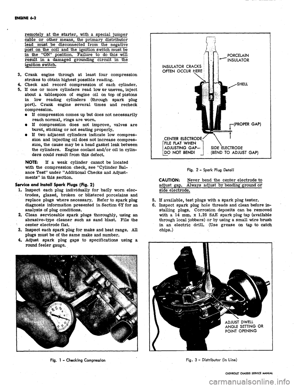
Service and Install Spark Plugs (Fig. 2)
1.
Inspect each plug individually for badly worn elec-
trodes,
glazed, broken or blistered porcelains and
replace plugs where necessary. Refer to spark plug
diagnosis information presented in Section 6Y for an
analysis of plug conditions.
2.
Clean serviceable spark plugs thoroughly, using an
abrasive-type cleaner such as sand blast. File the
center electrode flat.
3.
Inspect each spark plug for make and heat range. All
plugs must be of the same make and number.
4.
Adjust spark plug gaps to specifications using a
round feeler gauge.
PORCELAIN
INSULATOR
INSULATOR CRACKS
OFTEN OCCUR HERE
CENTER ELECTRODE
[FILE FLAT WHEN
ADJUSTING GAP-
[DO NOT BEND!
(PROPER GAP)
(BEND TO ADJUST GAP)
CAUTION:
adjust gap.
Fig.
2 - Spark Plug Detail
Never bend the center electrode to
Always adjust by bending ground or
side electrode.
If available, test plugs with a spark plug tester.
Inspect spark plug hole threads and clean before in-
stalling plugs. Corrosion deposits can be removed
with a 14 mm. x 1.25 SAE spark plug tap (available
through local jobbers) or by using a small wire brush
in an electric drill. (Use grease on tap to catch
chips.)
ADJUST DWELL
ANGLE SETTING OR
POINT OPENING
Fig.
1 - Checking Compression
Fig.
3 - Distributor (In Line)
CHEVROLET CHASSIS SERVICE MANUAL
Page 270 of 659
ENGINE
6-5
Service Battery and Battery Cables
1.
Measure the specific gravity of the electrolyte in
each cell (fig. 6). If it is below 1.230 (corrected to
80°F.) recharge with a slow rate charger, or if de-
sired, further check battery.
2.
Connect a voltmeter across the battery terminals and
measure the terminal voltage of the battery during
cranking (disconnect the coil primary lead at the
negative terminal during this check to prevent engine
from firing). If the terminal voltage is less than 9.0
volts at room temperature, approximately 80°
±
20°
F.,
the battery should be further checked. See
Section 6Y for further tests.
3.
Inspect for signs of corrosion on battery, cables and
surrounding area, loose or broken carriers, cracked
or bulged cases,- dirt and acid, electrolyte leakage
and low electrolyte level. !Fill cells to proper level
with distilled water or water passed through a
"demineralizer".
The top of the battery should be clean and the bat-
tery hold-down bolts properly tightened. Particular
care should be taken to see that the top of the battery
is kept clean of acid film and dirt. When cleaning
batteries, wash first with a dilute ammonia or soda
solution to neutralize any acid present and then flush
off with clean water. Keep vent plugs tight so that
the neutralizing solution does not enter the cell. The
hold-down bolts should be kept tight enough to prevent
the battery from shaking around in its holder, but
they should not be tightened to the point where the
battery case will be placed under a severe strain.
To insure good contact, the battery cables should
be tight on the battery posts. Oil battery terminal
felt washer. If the battery posts or cable terminals
are corroded, the cables should be cleaned separately
with a soda solution and wire brush. After cleaning
and before installing clamps, apply a thin coating of
petrolatum to the posts and cable clamps to help
retard corrosion.
If the battery has remained undercharged, check
for loose or defective fan belt, defective Delcotron,
high resistance in the charging circuit, oxidized
regulator contact points, or a low voltage setting.
If the battery has been using too much water, the
voltage output
is-
too high.
Service Deicotron and Regulator
The Delcotron and regulator tests during tune up con-
sist of the above battery tests; the condition of the battery
indicating further tests and adjustments as outlined in
Section 6Y.
Service Belts (Fig. 7)
Inspect belt condition.
Check and adjust if necessary for correct tension of
belt, as follows:
• Using a strand tension gauge, check the belt tension.
• Adjust belt until the specified tension is reached.
(See Tune Up Chart.)
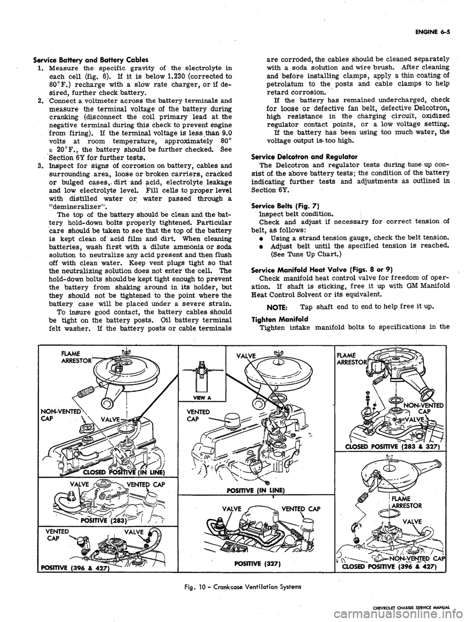
Service Manifold Heat Valve (Figs. 8 or 9)
Check manifold heat control valve for freedom of oper-
ation. If shaft is sticking, free it up with GM Manifold
Heat Control Solvent or its equivalent.
NOTE: Tap shaft end to end to help free it up.
Tighten Manifold
Tighten intake manifold bolts to specifications in the
FLAME
ARRESTOR
FLAME
ARRESTOR
NON-VENTED\
CAP
V\ VALVE
CLOSED
POSITIVE (283 & 327)
POSITIVE
(IN LINE)
POSITIVE
(327)
POSITIVE
(396 & 427)
Fig.
10 -
Crank case
Ventilation Systems
CHEVROLET CHASSIS SERVICE MANUAL
Page 273 of 659
ENGINE
6-8
Check
and
Adjust Ignition Timing
(Fig. 13)
1.
Disconnect
the
distributor spark advance hose
and
plug
the
vacuum source opening.
2.
Start engine
and run at
idle speed
(see
tune
up
chart).
3.
Aim
timing light
at
timing
tab.
NOTE:
- The
markings
on the
tabs
are in 2°
increments
(the
greatest number
of
markings
on
the
"A"
side
of the "O"). the "O"
markings
is
TDC
of
#1 cylinder
and all
BTDC settings fall
on
the
"A"
(advance) side
of "O".
4.
Adjust
the
timing
by
loosening
the
distributor clamp
and
,
rotating
the
distributor body
as
required, then
tighten
the
clamp.
5.
Stop engine
and
remove timing light
and
reconnect
the spark advance hose.
Adjust Idle Speed
and
Mixture
(Fig. 14)
(Except when
equipped with
Air
Injection Reactor System)
1.
As a
preliminary adjustment, turn idle mixture
screws lightly
to
seat
and
back
out 2
turns.
CAUTION:
Do not
turn idle mixture screw
tightly against seat
or
damage
may
result.
2.
With engine running
at
operating temperature (choke
wide open) adjust idle speed screw
to
bring idle
speed
to
specified
rpm
(automatic transmission
in
drive, manual transmission
in
neutral).
3.
Adjust idle mixture screw
to
obtain highest steady
idle speed
(1/4
turn
out
from lean roll).
4.
Repeat Steps
2 and 3 as
needed
for
final adjustment.
5.
Shut down
the
engine, remove gauges
and
install
air
cleaner.
Adjust Idle Speed
and
Mixture
(Fig. 14)
(With
Air
Injection Reactor System)
The recommended adjustment procedure
for Air
Injec-
tion Reactor System equipped engines
is as
follows:
1.
As a
preliminary adjustment, turn idle mixture
screws lightly
to
seat
and
than back
out 3
turns.
CAUTION:
Do not
turn idle mixture screw
tightly against seat
or
damage
may
result.
2.
With engine running
at
operating temperature, choke
wide open,
and
parking brake applied, adjust idle
specified idle speed (automatic
"drive"-manual transmission
in
to
in
screw
transmission
"neutral").
;3.
Adjust idle mixture screw (turn
in) to
"lean roll"
position; then turn screw
out 1/4
turn
(1/4
turn rich
from "lean roll").
The
definition
of
"lean roll" point
is
a 20 to 30 rpm
drop
in
engine speed, obtained
by
leaning
the
idle mixture.
4.
Repeat Steps
2 and 3 as
needed
for
final adjustments.
ADDITIONAL CHECKS
AND
ADJUSTMENTS
Testing Crankcase Ventilation Valve
(Fig. 15) 0
1.
Connect tachometer
and
vacuum gauge
as for
idle
speed
and
mixture adjustment.
2.
Set
parking brake, start engine
and
adjust idle speed
and mixture.
3.
Disconnect ventilation hose
at
valve, block opening
of
valve
and
read engine
rpm
change.
4.
A
change
of
less than
50 rpm
indicates
a
plugged
ventilation valve
-
replace
the
valve.
Cylinder Balance Test
(Fig. 16)
It
is
often difficult
to
locate
a
weak cylinder.
A com-
pression test,
for
example, will
not
locate
a
leaky intake
manifold,
a
valve
not
opening properly
due to a
worn
camshaft,
or a
defective spark plug.
With
the
cylinder balance test,
the
power output
of one
cylinder
may be
checked against another, using
a set of
grounding leads. When
the
power output
of
each cylinder
is
not
equal,
the
engine will lose power
and run
roughly.
Perform
a
cylinder balance test
as
follows:
1.
Connect
the
tachometer
and
vacuum gauge.
2.
Start engine
and run at 1500 rpm.
3.
Ground large clip
of
grounding leads
and
connect
in-
dividual leads
to all
spark plugs except
the
pair being
tested.
Divide
the
firing order
in
half
and
arrange
one
half
over
the
other.
The
cylinders
to be
tested together
ap-
pear
one
over
the
other.
L4 Firing Order
V8 Firing Order
1-8-4-3-6-5-7-2
1-6, 8-5, 4-7, 3-2
1-3-4-2
= 1-3
4-2
L6 Firing Order
1-5-3-6-2-4
=
=
1-4. 3-2
1-5-3
6-2-4
1-6, 5-2, 3-4
1-8-4-3
6-5-7-2
4.
Operate engine
on
each pair
of
cylinders
in
turn
and
note engine
rpm and
manifold vacuum
for
each pair.
A variation
of
more than
1
inch
of
vacuum
or 40 rpm
between pairs
of
cylinders being tested indicates that
the cylinders
are off
balance.
Battery
The battery should
be
checked with special testing
equipment
and to the
equipment manufacturers specifica-
tions.
See
Section 6Y
for
complete information
on
battery
tests.
Ignition
The following additional ignition checks
may be
made
with
any of
several pieces
of
equipment available
for un-
covering
the
source
of
engine difficulties.
The
specific
operating instructions
of the
equipment manufacturer
should
be
followed:
Cranking voltage
Ignition switch
Distributor resistance
Secondary resistance
Ignition output
and
secondary leakage
Cranking Voltage
(Fig. 17)
1.
Disconnect coil primary lead
at the
coil negative
terminal
to
prevent engine from firing during
cranking.
2.
Connect voltmeter between primary terminal
of coi|
(resistance wire side)
and
ground.
3.
Operate starting motor.
CHEVROLET CHASSIS SERVICE MANUAL
Page 275 of 659
ENGINE 6-10
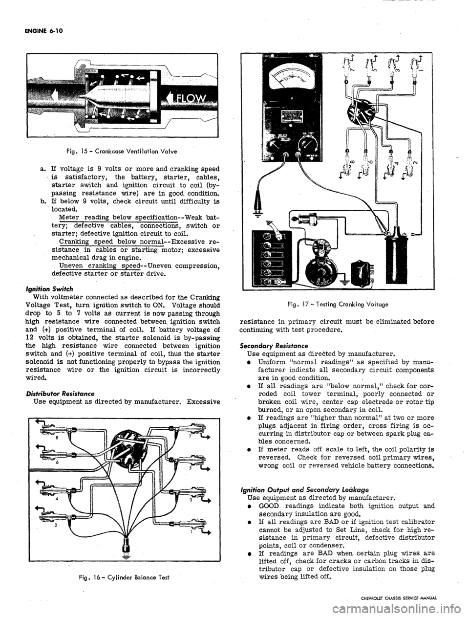
Fig.
15 - Crank case Ventilation Valve
a. If voltage is 9 volts or more and cranking speed
is satisfactory, the battery, starter, cables,
starter switch and ignition circuit to coil (by-
passing resistance wire) are in good condition.
b.
If below 9 volts, check circuit until difficulty is
located.
Meter reading below specification—Weak bat-
tery; defective cables, connections, switch or
starter; defective ignition circuit to coil.
Cranking speed below normal--Excessive re-
sistance in cables or starting motor; excessive
mechanical drag in engine.
Uneven cranking speed—Uneven compression,
defective starter or starter drive.
Ignition Switch
With voltmeter connected as described for the Cranking
Voltage Test, turn ignition switch to ON. Voltage should
drop to 5 to 7 volts as current is now passing through
high resistance wire connected between ignition switch
and (+) positive terminal of coil. If battery voltage of
12 volts is obtained, the starter solenoid is by-passing
the high resistance wire connected between ignition
switch and (+) positive terminal of coil, thus the starter
solenoid is not functioning properly to bypass the ignition
resistance wire or the ignition circuit is incorrectly
wired.
Distributor Resistance
Use equipment as directed by manufacturer.
Excessive
(t n ti ft
Fig.
16 - Cylinder Balance Test
Fig.
17 - Testing Cranking Voltage
resistance in primary circuit must be eliminated before
continuing with test procedure.
Secondary Resistance
Use equipment as dire6ted by manufacturer.
• Uniform "normal readings" as specified by manu-
facturer indicate all secondary circuit components
are in good condition.
• If all readings are "below normal," check for cor-
roded coil tower terminal, poorly connected or
broken coil wire, center cap electrode or rotor tip
burned, or an open secondary in coil.
• If readings are "higher than normal" at two or more
plugs adjacent in firing order, cross firing is oc-
curring in distributor cap or between spark plug ca-
bles concerned.
• If meter reads off scale to left, the coil polarity is
reversed. Check for reversed coil primary wires,
wrong coil or reversed vehicle battery connections.
Ignition Output and Secondary Leakage
Use equipment as directed by manufacturer.
• GOOD readings indicate both ignition output and
secondary insulation are good.
• If all readings are BAD or if ignition test calibrator
cannot be adjusted to Set Line, check for high re-
sistance in primary circuit, defective distributor
points, coil or condenser.
e If readings are BAD when certain plug wires are
lifted off, check for cracks or carbon tracks in dis-
tributor cap or defective insulation on those plug
wires being lifted off.
CHEVROLET CHASSIS SERVICE MANUAL
Page 277 of 659
ENGINE
6-12
ENGINE
MECHANICAL
IN LINE
INDEX
Page
General Description . „ 6-12
Component Replacement and Adjustment 6-12
.Engine Assembly 6-12
Removal 6-12
Installation 6-13
Manifold Assembly 6-14
Removal . 6-14
Installation 6-14
Rocker Arm Cover . 6-14
Removal 6-14
mstallation . . . 6-14
Valve Mechanism
......
1 6-14
Removal 6-14
Installation and Adjustment . 6-14
Valve Lifters
..............
6-15
Locating Noisy Lifters
„.;....
6-15
Removal
.'.*...•
6-15
Installation . 6-15
Valve Stem Oil Seal and/or Valve Spring . 6-16
Replacement . 6-16
Cylinder Head Assembly . 6-16
Removal 6-16
Installation . 6-16
Oil Pan . » 6-17
Removal . . . ; . . 6-17
Installation
.........
. 6-17
Oil Pump . 6-18
Page
Removal . 6-18
Installation . 6-18
Oil Seal (Rear Main) . 6-19
Replacement 6-19
Crankshaft Pulley and Hub 6-19
Removal 6-19
Installation 6-19
Torsional Damper 6-19
Removal 6-19
Installation 6-19
Crankcase Front Cover . 6-20
Removal . 6-20
Installation 6-20
•
Oil Seal (Front Cover) 6-20
Replacement 6-20
Camshaft 6-21
Measuring Lobe Lift . ... .
.-.••.-.
6-21
Removal 6-21
Installation 6-22
Timing Gears
..••••.............••• 6—22
Replacement
6-22
Flywheel
6-22
Removal
* 6-22
Installation
6-22
Engine
Mounts
6-23
Replacement
(Front)
6-23
Replacement
(Rear)
. 6-23
GENERAL DESCRIPTION
The
In
Line engines
(fig. 1L)
covered
in
this section
are
the 1H3 cu. in. L4, the 194,
230
and
250
cu. in. L6,
regardless
of
which passenger vehicle they
are
used
in.
This section covers
the
removal
and
installation
of en-
gine assemblies;
the
removal, installation
and
adjustment
of some sub-assemblies
and
replacement
of
some
com-
ponents.
For
service
to all
components
and
sub-assem-
blies (after removal)
and
removal
of
some sub-assem-
blies,
refer
to
Section
6 of the
Chassis Overhaul Manual.
Because
of the
interchangeability
and
similarity
of
many engine sub-assemblies
and
engine parts, regardless
of which passenger vehicle they
are
used
in,
typical illus-
trations
and
procedures
are
used except where specific
illustrations
or
procedures
are
necessary
to
clarify
the
operation. Although illustrations showing bench opera-
tions
are
used, most single operations, when
not
part
of a
general overhaul, should
be
performed
(if
practical) with
the engine
in the
vehicle.
COMPONENT REPLACEMENT
AND
ADJUSTMENT
ENGINE ASSEMBLY
Removal
1.
Drain cooling system
and
engine
oil.
2.
Remove
air
cleaner
and
disconnect battery cables
at 7.
battery.
3.
Remove hood
as
outlined
in
Section 11.
4.
Remove radiator
and
radiator shroud
as
outlined
in
Section 13.
5.
Remove
fan
blade
and
pulley
as
outlined
in
Section
6K.
6. Disconnect wires
at:
• Starter Solenoid
8.
• Delcotron
9.
Temperature Switch
Oil Pressure Switch
Coil
Disconnect:
Accelerator linkage
at
manifold bellerank.
Exhaust pipe
at
manifold flange.
.
Fuel line (from tank)
at
fuel pump.
Vacuum line
to
power brake unit
at
manifold
(if
so equipped).
• Power steering pump lines
at
pump
end (if so
equipped).
Raise vehicle
and
place
on
jack stands.
Remove propeller shaft.
CHEVROLET CHASSIS SERVICE MANUAL
Page 279 of 659
ENGINE 6-14
b.
Bolt transmission to engine, then raise engine and
transmission assembly and install flywheel to
converter attaching bolts.
c. Install converter
housing*
underpan and starter.
3.
Tilt and lower engine and transmission assembly into
the chassis as a unit, guiding engine to align front
mounts with frame supports.
4.
Install front mount through bolts and torque to
specifications.
5.
Raise engine enough to install rear crossmember,
then install crossmember, install rear mount, lower
engine and torque bolts to specifications.
6. Remove lifting device and lifting adapter then install
rocker arm cover as outlined.
7.
On synchromesh equipped vehicles, install clutch
cross shaft engine bracket, then adjust and connect
clutch as outlined in Section 7.
8. Connect:
• Speedometer cable.
• Shift linkage at transmission.
9; Install propeller shaft.
10.
Remove jack stands and lower vehicle.
11.
Connect:
Power steering pump lines (if disconnected).
Vacuum line to power brake unit (if disconnected).
Fuel line at fuel pump.
Exhaust pipe at manifold flange.
Accelerator linkage at manifold bellcrank.
12.
Connect wires at:
Coil
Oil pressure switch
Temperature switch
Delcotron
Starter solenoid
13.
Install pulley, fan blade and fan belt as outlined in
Section 6K.
14.
Install radiator and shroud as outlined in Section 13.
15.
Install and adjust hood as outlined in Section 11.
16.
Connect battery cables.
17.
Fill with coolant, engine oil and transmission oil,
then start engine and check for leaks.
18.
Perform necessary adjustments and install air
cleaner.
MANIFOLD ASSEMBLY
Removal
1.
Remove air cleaner.
2.
Disconnect both throttle rods at bellcrank and re-
move throttle return spring.
3.
Disconnect fuel and vacuum lines at carburetor.
Disconnect choke cable on \A engines.
4.
Disconnect crankcase ventilation hose at rocker arm
cover.
5.
Disconnect exhaust pipe at manifold flange and dis-
card packing.
6. Remove manifold attaching bolts and clamps then
remove manifold assembly and discard gaskets.
7.
Check for cracks in manifold castings.
8. If necessary to replace either intake or exhaust
manifolds, separate them by removing one bolt and
two nuts at center of assembly. Reassemble mani-
folds using a new gasket. Tighten finger tight and
torque to specifications after assembly to cylinder
head. Transfer all necessary parts.
Installation
1.
Clean gasket surfaces on cylinder head and
manifolds*
2.
Position new gasket over manifold end studs on head
and carefully install the manifold in position making
sure the gaskets are in place.
3.
Install bolts and clamps while holding manifold in
place with hand.
4.
Torque bolts to specifications.
NOTE: On L6 engines center bolt and end bolt
torque differ.
5.
Connect exhaust pipe to manifold using a new
packing.
6. Connect crankcase ventilation hose at rocker arm
cover.
7.
Connect fuel and vacuum lines at carburetor.
8. On L4 engines connect choke cable and adjust as out-
lines in Section 6M.
9. Connect throttle rods at bellcrank and install throttle
return spring.
10.
Install air cleaner, start engine, check for leaks and
adjust carburetor idle speed and mixture.
ROCKER ARM COVER
Removal
1.
Disconnect crankcase ventilation hose(s) at rocker
arm cover.
2.
Remove air cleaner.
3.
Disconnect temperature wire from rocker arm cover
clips.
4.
Remove rocker arm cover. '
CAUTION: Do Not pry rocker arm cover loose
Gaskets adhering to cylinder head and rocker
arm cover may be sheared by bumping end of
rocker arm cover rearward with palm of hand or
a rubber mallet.
Installation
1.
Clean gasket surfaces on cylinder head and rocker
arm cover with degreaser then, using anew gasket,
install rocker arm cover and torque bolts to
specifications.
2.
Connect temperature wire at rocker arm cover clips.
3.
Install air cleaner.
4.
Connect crankcase ventilation hoses.
VALVE MECHANISM
Removal
1.
Remove rocker arm cover as outlined.
2.
Remove rocker arm nuts, rocker arm
balls,
rocker
arms and push rods.
NOTE:
Place rocker arms, rocker arm balls
and push rods in a rack so they may be rein-
stalled in the same location.
Installation and Adjustment
NOTE:
Whenever new rocker arms and/or
rocker arm balls are being installed, coat bear-
ing surfaces of rocker arms and rocker arm
balls with Molykote or its equivalent.
1.
Install push rods,
socket.
Be sure push rods seat in lifter
CHEVROLET CHASSIS SERVICE MANUAL