lock CHEVROLET CAMARO 1967 1.G Chassis Service Manual
[x] Cancel search | Manufacturer: CHEVROLET, Model Year: 1967, Model line: CAMARO, Model: CHEVROLET CAMARO 1967 1.GPages: 659, PDF Size: 114.24 MB
Page 123 of 659

CORVETTE
BODY
1B-16
1.
Ventilator Assembly
2.
Ventilator Assembly Mounting
Screw
3.
Window Drive
Pin
Retaining Screw
4.
Regulator Mounting Screw
Fig.
34-Model 19467 Ventilator Assembly
5. Regulator
6. Ventilator Assembly Mounting
Nut - Upper
7. Ventilator Assembly Mounting
Stud - Upper
8. Ventilator Assembly Mounting
Stud - Lower
9. Ventilator Assembly Mounting
Nut -
•
Lower
DOOR LOCK AND REMOTE CONTROLS
For parts identification refer to Figure 46.
Removal
1.
Roll door window fully up.
2.
Remove door trim panel as outlined in this section.
3.
Remove two screws holding door lock remote con-
trol assembly and disengage control from lock re-
mote control rod.
4.
Remove cover from larger access hole in door inner
panel.
5. Remove two screws retaining remote locking control
assembly and disengage control from remote control
locking rod.
6. Remove 4 screws retaining lock assembly, disengage
control rods and remove lock from door pocket.
Installation
To install lock and controls follow removal assembly
in reverse order. All components should be lubricated
before installation.
OUTER HANDLE
For parts identification refer to Figure 47.
Removal
1.
Remove door trim panel as outlined in this section.
Remove larger access hole cover.
2.
Roll door window fully up.
3.
Working through access hole, remove 2 door handle
retaining screws.
4.
Remove handle from door outer surface. Retrieve
reinforcement from inside door pocket. Discard old
Installation
1.
Install new gaskets and position door handle on door
outer panel.
2.
Position reinforcement on door inner panel and in-
stall handle retaining screws.
3.
Carefully check operation of door lock.
4.
Install door trim panel as outlined in this section.
CHEVROLET CHASSIS SERVICE MANUAL
Page 124 of 659
CORVETTE BODY 1B-17
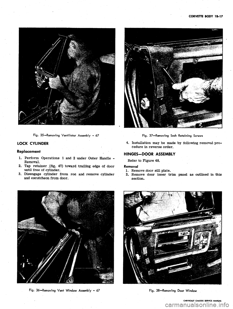
Fig.
35—Removing Ventilator Assembly - 67
LOCK CYLINDER
Replacement
1.
Perform Operations 1 and 2 under Outer Handle -
Removal.
2.
Tap retainer t(flLg. 47) toward trailing edge of door
until free of cylinder.
3.
Disengage cylinder from rod and remove cylinder
and escutcheon from door.
Fig.
37—Removing Sash Retaining Screws
4.
Installation may be made by following removal pro-
cedure in reverse order.
HINGES-DOOR ASSEMBLY
Refer to Figure 48.
Removal
1.
Remove door sill plate.
2.
Remove door inner trim panel as outlined in this
section.
Fig.
36—Removing Vent Window Assembly - 67
Fig.
38-Removing Door Window
CHEVROLET CHASSIS SERVICE /MANUAL
Page 125 of 659
CORVETTE BODY 18-18
TRIM
PANEL
VIEW A
view B
UPPER GUIDE
\
REGULATOR / /
ASSEMBLY / A-
RAIL ,
MS
o Y \ C^^^
Jlf
3) \ JJ
LOWER GUIDE RAIL
y
< REAR
/ CHANNEL
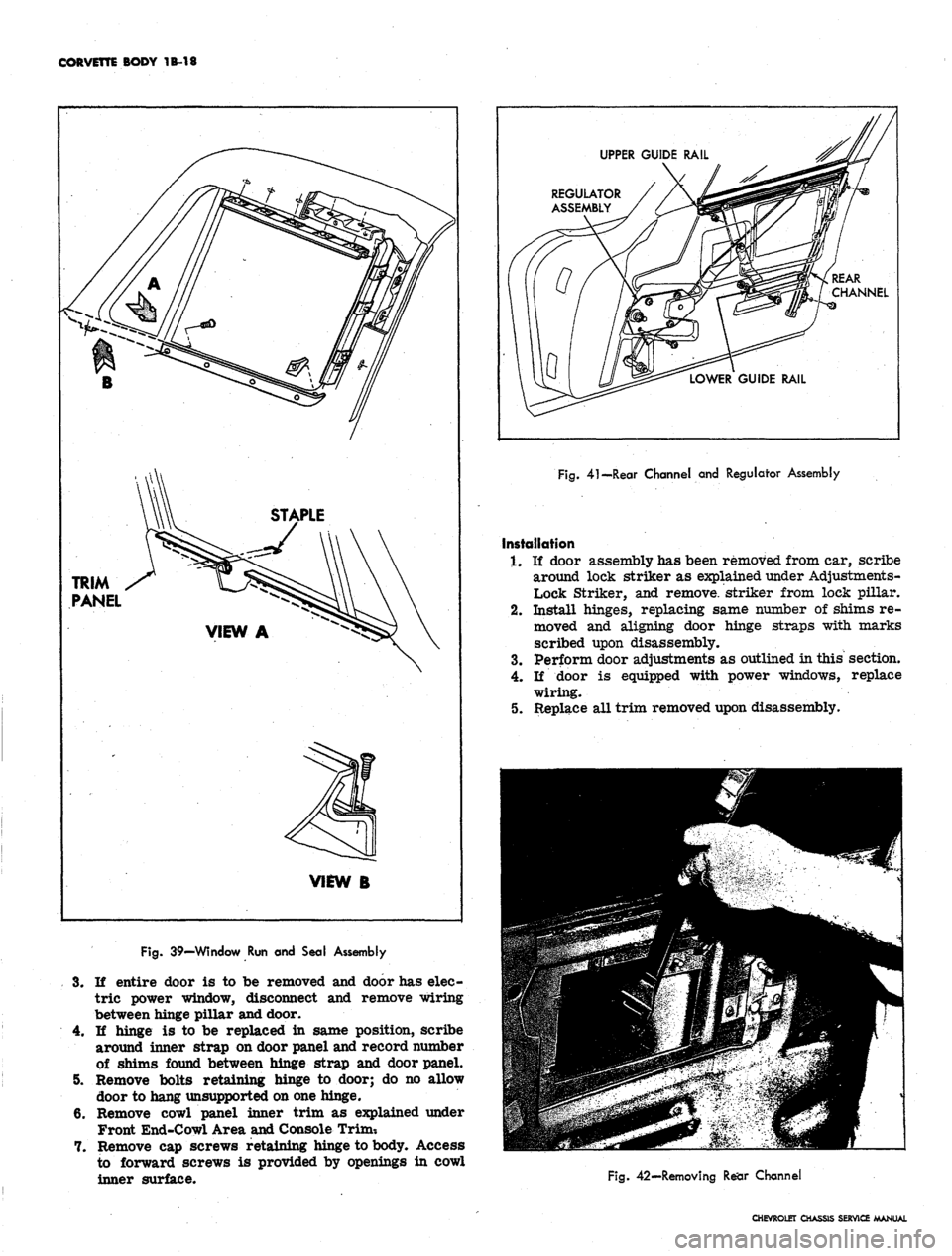
Fig.
41—Rear Channel and Regulator Assembly
Installation
1.
If door assembly has been removed from car, scribe
around lock striker as explained under Adjustments-
Lock Striker, and remove, striker from lock pillar.
2.
Install hinges, replacing same number of shims re-
moved and aligning door hinge straps with marks
scribed upon disassembly.
3.
Perform door adjustments as outlined in this section.
4.
If door is equipped with power windows, replace
wiring.
5.
Replace all trim removed upon disassembly.
Fig.
39—Window Run and Seal Assembly
3.
If entire door is to be removed and door has elec-
tric power window, disconnect and remove wiring
between hinge pillar and door.
4.
If hinge is to be replaced in same position, scribe
around inner strap on door panel and record number
of shims found between hinge strap and door panel.
5. Remove bolts retaining hinge to door; do no allow
door to hang unsupported on one hinge.
6. Remove cowl panel inner trim as explained under
Front End-Cowl Area and Console Trim-.
7. Remove cap screws retaining hinge to body. Access
to forward screws is provided by openings in cowl
inner surface.
Fig.
42—Removing Rear Channel
CHEVROLET CHASSIS SERVICE MANUAL
Page 126 of 659

CORVETTE BODY 1B-T9
Fig.
43—Removing Regulator Assembly
REAR QUARTER
DOOR SILL PLATE AND MOLDING
Figure 49 shows assembly details of both the door sill
plate and molding. The sill plate which retains the car-*
pet, the cowl trim windlace and lock pillar front edge
trim are retained to the body by six screws.
The molding assembly, which replaces a rocker panel,
is quickly and easily replaced by removing 10 retaining
screws. The sill molding retainer is also fastened to the
body with screws.
REAR END
FOLDING TOP COMPARTMENT LID
Adjustments
Hinges
The folding top compartment lid should be adjusted so
that in the closed position the surface of the lid is flush
with surrounding body surfaces and space between lid
edge and body is 1/16" to 3/16" at sides and 3/16" to
1/4" at rear. Whenever lid position is changed on hinges,
lock engagement must be inspected and adjusted if neces-
sary. Adjust hinge position as follows:
1.
Scribe a line on lid surface following contour of hinge
strap.
This will ease observation of lid movement
during adjustment (fig. 51).
2.
To raise or lower top surface of lid, add or remove
hinge shims.
3.
To adjust spacing between lid edges and body, loosen
hinge-to-lid screws and shift lid as required.
Lock
Lock engagement may be adjusted as follows:
1.
Striker plates may be shimmed to adjust the depth
of lock engagement in striker plate. When this ad-
justment is made, release of lock should be tested
and adjusted as required.
2.
Release of lock may be adjusted by loosening lock
assembly retaining bolts and moving lock in ap-
propriate direction to the limit of slotted holes in
, lock base. Further adjustment may be gained by
moving cable retainer in appropriate direction.
Hinges
(Refer to Figure 52)
Removal
1.
Scribe around hinge as shown in Figure 51.
2.
Hinge may be removed as an assembly by opening
top compartment lid fully and removing 3 retaining
screws. Note number of shims found between hinge
frame and compartment floor.
3.
To remove spring from hinge assembly, close top
compartment lid as far as possible and insert Tool
J-9559 between expanded coils in spring. Opening
top compartment lid fully will allow removal of
spring as shown in Figure 53.
4.
As soon as spring is removed, insert long bolt sup-
plied with J-9559 through holes in end of tool, pass-
ing it through spring, and install nut on bolt.
Spring may be removed from J-9559 or J-9559 may be
installed in a new spring, by the following method:
1.
Place a closed 6 or 8 inch "C" clamp in a vise or
fasten it to a heavy bench top (bench should be fas-
tened to floor).
2.
Hook one end of spring in clamp and the other end
in hook of chain hoist, "cherrypicker" or equivalent,
as shown in Figure 54.
3.
Stretch the spring enough to allow insertion of
J-9559. Install through bolt if spring is not to be in-
stalled on hinge at once.
installation
1.
Install same number of shims as removed or, if
repairing collision damage, etc., position hinge in
compartment, install upper mounting screws, fill
gap between floor and hinge frame with shims and
install lower mounting screw.
2.
If spring has been removed from hinge, install
spring in J-9559 and place spring on hinge with com-
partment lid raised; closing lid releases J-9559 for
removal. Upper end of spring should rest in one of
three notches yielding best lid operation. About 3
pounds pressure should be necessary to close lid.
Lock
Removal
1.
Remove cable mounting clamps. Remove retainer
from control cable assembly and disengage cable
from control.
2.
Scribe a mark on lid following outer contour of lock
assembly.
3.
Remove 3 lock assembly retaining screws and re-
move lock from compartment lid.
Installation
1.
Place lock assembly on compartment lid within
scribed line and install retaining screws.
2.
Install end of cable in control assembly and fasten
retainer securely.
3.
Test operation of lock thoroughly, adjusting if neces-
sary as outlined in this section.
Control
Removal
1.
Remove inner mounting clamps from both cables
and disengage cables from control by removing
retainers.
CHEVROLET CHASSIS SERVICE MANUAL
Page 127 of 659
CORVETTE BODY
1B-20
DOOR
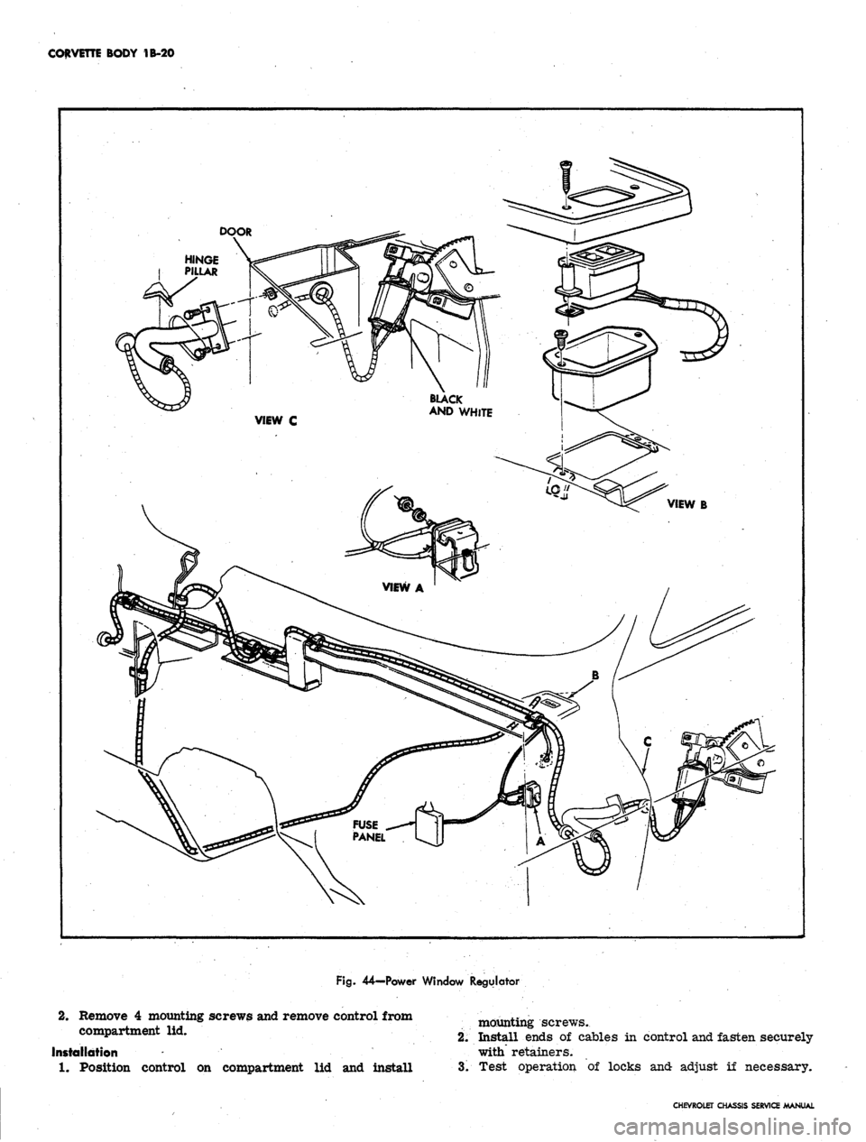
Fig.
44—Power Window Regulator
2.
Remove
4
mounting screws and remove control from
compartment
lid.
Installation
*
1.
Position control
on
compartment
lid and
install
mounting screws.
2.
Install ends of cables in control and fasten securely
with retainers.
3.
Test operation of locks and adjust if necessary.
CHEVROLET CHASSIS SERVICE MANUAL
Page 128 of 659

CORVETTE BODY 1B-21
Fig.
45—
Locking Regulator Arm in Place
REAR WINDOW-ADHESIVE CAULKED-
19437 MODEL
For parts identification refer to Figure 55.
1.
Remove the 2 rear window garnish moldings by re-
moving the 14 attaching screws.
2.
Pry molding caps from reveal moldings.
3.
Carefully remove lower, side, and top reveal mold-
ings after marking their position on body with tape.
4.
Secure one end of steel music wire to piece of wood
for handle. Insert other end through caulking mater-
ial at lower corner of rear window; then secure end
of wire to another piece of wood (fig. 56).
5. With the aid of helper, carefully cut through caulking
material (using a sawing motion) with the steel wire;
up side of window, across top, down opposite side,
and across bottom of window.
6. Remove old glass from window opening.
7. Using a sharp scraper or wood chisel, remove ad-
hesive caulking material from body pinchweld flange.
NOTE:
It is not necessary to clean off all the
old caulking material completely from body
opening; however, there should not be any loose
pieces of caulking material left in the opening.
8. Check all reveal molding retaining clips for damage
(24 required). Replace those that are bent or dis-
torted with clips provided in kit.
9. Using weatherstrip adhesive, cement rubber spacers
at bottom, sides, and top of window opening. The
step-type spacers are used at bottom and sides, the
flat type are used at the top, sides, and bottom of
window opening as shown on Figure 55.
10.
Using suction cup holders, position replacement
glass in body opening. Carefully check relationship
of glass to body pinchweld completely around open-
ing. The overlap of glass to body pinchweld and re-
taining flanges should be equal with a minimum over-
lap of 3/16M. Where necessary, position shims under
the lower spacers to obtain required overlap of glass
to body upper and lower flanges.
11.
After proper glass to pinchweld relationship has
been attained, mark position with grease pencil on
glass and body as shown in Figure 57.
12.
Remove glass from body opening and place on pro-
tected surface.
13.
Clean inside edge surface of glass so that glass is
free of any foreign material (oil, grease, etc.).
Using 3/4" masking tape, place tape approximately
1/2 inch from edge of inside surface of glass com-
pletely around glass. Then apply a film of silane
primer to inside edge surface completely around
glass,
also apply silane primer to sealing surface
of pinchweld as shown in Figure 58.
Fig.
46—Door Lock and Remote Controls
1.
Door Lock Remote Control
Assembly
2.
Door Lock Remote Control Knob
3. Door Lock Remote Control Rod
4.
Remote Control Locking Rod
5. Remote Locking Control
Assembly
6. Lock Assembly
CHEVROLET CHASSIS SERVICE MANUAL
Page 129 of 659
CORVETTE BODY 1B-22
16.
17.
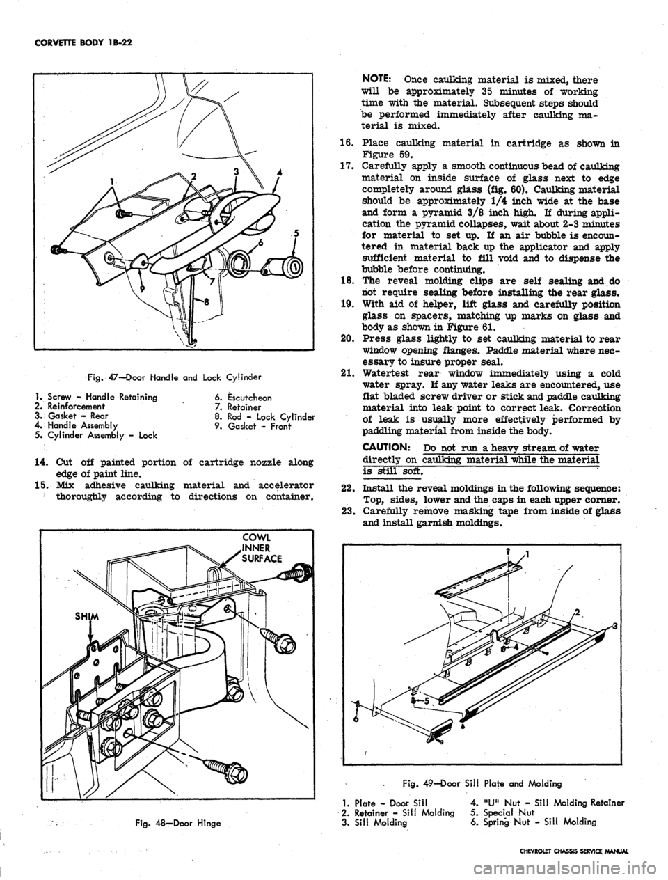
Fig.
47-Door Handle and Lock Cylinder
18.
19.
20.
21.
1.
Screw - Handle Retaining
2.
Reinforcement
3. Gasket - Rear
4.
Handle Assembly
5. Cylinder Assembly - Lock
6. Escutcheon
7.
Retainer
8. Rod - Lock Cylinder
9. Gasket - Front
14.
Cut off painted portion of cartridge nozzle along
edge of paint line.
15.
Mix adhesive caulking material and accelerator
] thoroughly according to directions on container.
NOTE:
Once caulking material is mixed, there
will be approximately 35 minutes of working
time with the material. Subsequent steps should
be performed immediately after caulking ma-
terial is mixed.
Place caulking material in cartridge as shown in
Figure 59.
Carefully apply a smooth continuous bead of caulking
material on inside surface of glass next to edge
completely around glass (fig. 60). Caulking material
should be approximately 1/4 inch wide at the base
and form a pyramid 3/8 inch high. If during appli-
cation the pyramid collapses, wait about 2-3 minutes
for material to set up. If an air bubble is encoun-
tered in material back up the applicator and apply
sufficient material to fill void and to dispense the
bubble before continuing.
The reveal molding clips are self sealing and do
not require sealing before installing the rear glass.
With aid of helper, lift glass and carefully position
glass on spacers, matching up marks on glass and
body as shown in Figure 61.
Press glass lightly to set caulking material to rear
window opening flanges. Paddle material where nec-
essary to insure proper seal.
Watertest rear window immediately using a cold
water spray. If any water leaks are encountered, use
flat bladed screw driver or stick and paddle caulking
material into leak point to correct leak. Correction
of leak is usually more effectively performed by
paddling material from inside the body.
CAUTION: Do not run a heavy stream of water
directly on caulking material while the material
is still soft.
22.
Install the reveal moldings in the following sequence:
Top,
sides, lower and the caps in each upper corner.
23.
Carefully remove masking tape from inside of glass
and install garnish moldings.
Fig.
49—Door Sill Plate and Molding
Fig.
48—Door Hinge
1.
Plate - Door Sill
2.
Retainer - Sill Molding
3. Sill Molding
4.
"U" Nut - Sill Molding Retainer
5. Special Nut
6. Spring Nut - Sill Molding
CHEVROLET CHASSIS SERVICE MANUAL
Page 130 of 659
CORVETTE BODY 1B-23
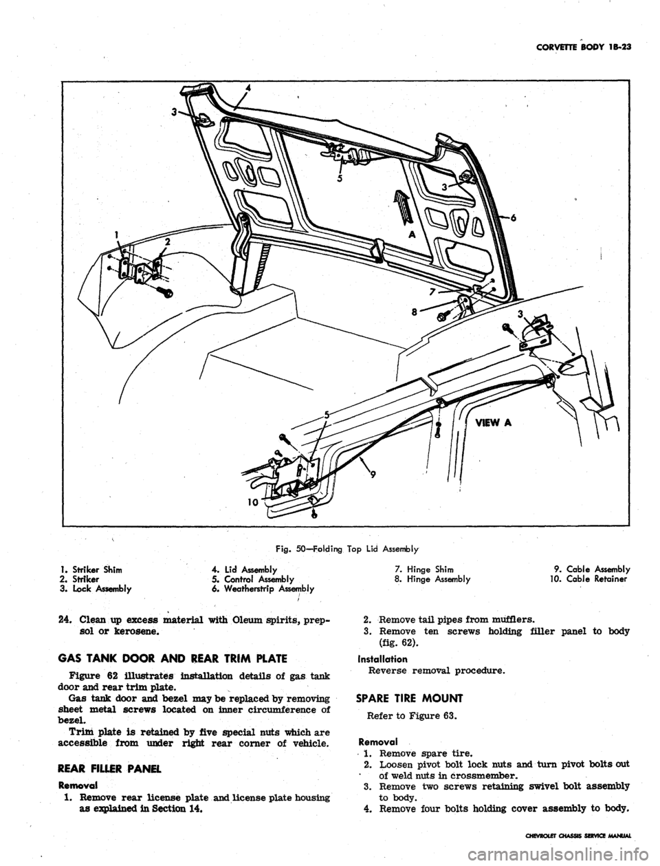
Fig.
50—Folding Top Lid Assembly
1.
Striker Shim
2.
Striker
3. Lock Assembly
4. Lid Assembly
5. Control Assembly
6. Weatherstrip Assembly
7. Hinge Shim
8. Hinge Assembly
9. Cable Assembly
10.
Cable Retainer
24.
Clean up excess material with Oleum spirits, prep-
sol or kerosene.
GAS TANK DOOR AND REAR TRIM PLATE
Figure 62 illustrates installation details of gas tank
door and rear trim plate.
Gas tank door and bezel may be replaced by removing
sheet metal screws located on inner circumference of
bezel.
Trim plate is retained by five special nuts which are
accessible from under right rear corner of vehicle.
REAR FILLER PANEL
Removal
1.
Remove rear license plate and license plate housing
as explained in Section 14.
2.
Remove tail pipes from mufflers.
3.
Remove ten screws holding filler panel to body
(fig. 62).
Installation
Reverse removal procedure.
SPARE TIRE MOUNT
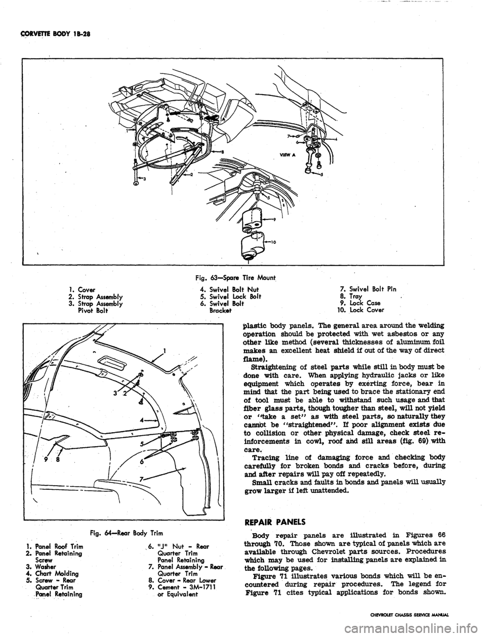
Refer to Figure 63.
Removal
1.
Remove spare tire.
2.
Loosen pivot bolt lock nuts and turn pivot bolts out
of weld nuts in crossmember.
3.
Remove two screws retaining swivel bolt assembly
to body.
4.
Remove four bolts holding cover assembly to body.
CHEVROLET CHASSIS SERVICE
Page 135 of 659
CORVETTE BODY 1B-28
Fig. 63—Spare Tire Mount
1.
Cover
2.
Strap Assembly
3. Strap Assembly
Pivot Bolt
Swivel Bolt Nut
Swivel Lock Bolt
Swivel Bolt
Bracket
7. Swivel Bolt Pin
8. Tray
9. Lock Case
10.
Lock Cover
1.
Panel Roof Trim
2.
Panel Retaining
Screw
3. Washer
4.
Chart Molding
5. Screw - Rear
Quarter Trim
Panel Retaining
Fig.
64—Rear Body Trim
6.
"J"
Nut - Rear
Quarter Trim
Panel Retaining
7. Panel Assembly - Rear
Quarter Trim
8. Cover - Rear Lower
9. Cement - 3M-1711
or Equivalent
plastic body panels. The general area around the welding
operation should be protected with wet asbestos or any
other like method (several thicknesses of aluminum foil
makes an excellent heat shield if out of the way of direct
flame).
Straightening of steel parts while still in body must be
done with care. When applying hydraulic jacks or like
equipment which operates by exerting force, bear in
mind that the part being used to brace the stationary end
of tool must be able to withstand such usage and that
fiber glass parts, though tougher than steel, will not yield
or "take a set" as with steel parts, so naturally they
cannot be "straightened". If poor alignment exists due
to collision or other physical damage, check steel re-
inforcements in cowl, roof and sill areas (fig. 69) with
care.
Tracing line of damaging force and checking body
carefully for broken bonds and cracks before, during
and after repairs will pay off repeatedly.
Small cracks and faults in bonds and panels will usually
grow larger if left unattended.
REPAIR PANELS
Body repair panels are illustrated in Figures 66
through 70. Those shown are typical of panels which are
available through Chevrolet parts sources. Procedures
which may be used for installing panels are explained in
the following pages.
Figure 71 illustrates various bonds which will be en-
countered during repair procedures. The legend for
Figure 71 cites typical applications for bonds shown.
CHEVROLET CHASSIS SERVICE MANUAL
Page 138 of 659
CORVETTE BODY 1B-31
1
^JS^ST**-
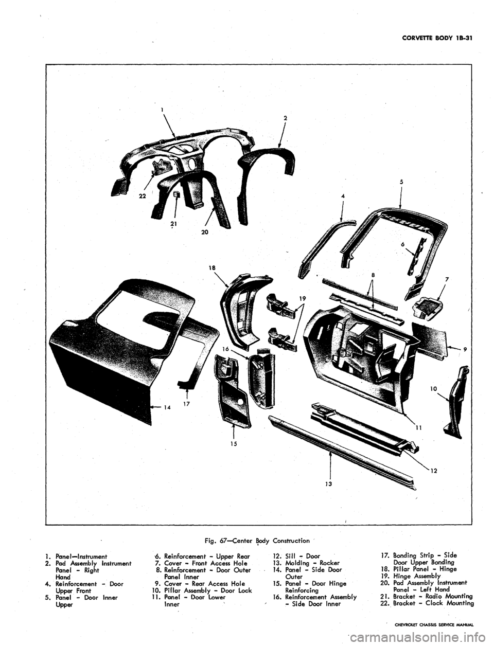
Fig.
67—Center Body Construction
1.
Panel—Instrument
2.
Pad Assembly Instrument
Panel - Right
Hand
4.
Reinforcement -. Door
Upper Front
5. Panel - Door Inner
Upper
6. Reinforcement - Upper Rear
7. Cover - Front Access Hole
8. Reinforcement - Door Outer
Panel inner
9. Cover - Rear Access Hole
10.
Pillar Assembly - Door Lock
11.
Panel - Door Lower
Inner
12.
Sill - Door
13.
Molding - Rocker
14.
Panel - Side Door
Outer
15.
Panet - Door Hinge
Reinforcing
16.
Reinforcement Assembly
- Side Door Inner
17.
Bonding Strip - Side
Door Upper Bonding
18.
Pillar Panel - Hinge
19.
Hinge Assembly
20.
Pad Assembly Instrument
Panel - Left Hand
21.
Bracket - Radio Mounting
22.
Bracket - Clock Mounting
CHEVROLET CHASSIS SERVICE MANUAL