tow CHEVROLET CAMARO 1967 1.G Chassis Manual Online
[x] Cancel search | Manufacturer: CHEVROLET, Model Year: 1967, Model line: CAMARO, Model: CHEVROLET CAMARO 1967 1.GPages: 659, PDF Size: 114.24 MB
Page 616 of 659
ACCESSORIES 15-7
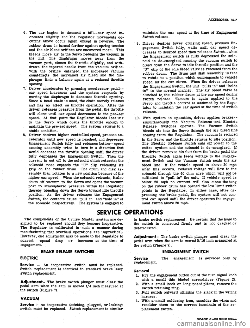
6. The car begins to descend a hill--car speed in-
creases slightly and the regulator movements oc-
curing above occur again except in reverse. The
rubber drum is turned further against spring tension
and the air bleed orifices are uncovered more. This
bleeds more air to the Servo reducing the vacuum in
the unit. The diaphragm moves away from the
vacuum port, closes the throttle slightly, and with-
draws the tapered needle from the vacuum orifice.
With the orifice enlarged, the increased vacuum
counteracts the increased air bleed and the dia-
phragm finds a balance again at a reduced throttle
opening.
7.
Driver accelerates by pressing accelerator pedal-
car speed increases and the system responds by
moving the diaphragm to decrease throttle opening.
Since a bead chain is used, the chain merely relaxes
and has no effect on throttle operation. After the
driver releases pressure from the pedal, the throttle
will close until car speed decreases to the pre-set
speed. At that point the Regulator bleeds less air
to the Servo which opens the throttle enough to
maintain the pre-set speed. The system returns to a
stable condition.
8. Driver desires higher controlled speed, presses ac-
celerator until new speed is reached, and depresses
Engagement Switch fully and releases button--speed
sensing assembly tries to turn in a direction that
would decrease the throttle opening until the driver
fully depresses the Engagement Switch. Then the
current is cut off to the solenoid which retracts; the
solenoid nose expands the "U" clip releasing its
grip on the rubber drum. The drum and disk as-
sembly then rotates to a new position because of the
higher car speed. When the solenoid retracts, it also
shuts off vacuum to the Servo and opens the vacuum
port to atmospheric pressure within the Regulator
thereby bleeding down the Servo toward idle throttle
position. As the driver releases the Engagement
Switch, the contacts cause "pull in" and "hold in" of
the solenoid respectively. The system is engaged to
maintain the car speed at the time of Engagement
Switch release.
9. Driver desires lower cruising speed, presses En-
gagement Switch fully, waits until car speed de-
creases to desired speed then releases Switch--when
the Engagement switch is fully depressed the sole-
noid is de-energized causing the vacuum switch to
bleed down the Servo to idle throttle position and the
"U"
clip of the idle bleed valve is released from the
rubber drum. The drum and disk assembly is free
to rotate to a position which corresponds to vehicle
speed as the car slows. When the driver releases
the Engagement Switch, the unit "pulls in" and "holds
in" in the normal manner. The air bleed valve is
clutched to, the rubber drum at the car speed during
switch release. Vacuum is again applied to the
Servo and throttle control is assumed by the Regu-
lator to maintain the car speed at the time of switch
release.
10.
With system in operation, driver applies brakes--
simultaneously the Vacuum Release and Electric
Release Switches operate. The Vacuum Switch
bleeds air into the Servo through the air bleed line
coming from the Regulator. The vacuum is reduced
in the Servo and the throttle returns to idle position.
The Electric Release Switch cuts off power to the
entire system and the solenoid is de-energized. If
the driver removes his foot from the brake pedal the
Electric Switch again feeds voltage to the Engage-
ment Switch and the Vacuum Switch seals the air
bleed line. If the vehicle speed is above 20 mph
when this occurs, reduced voltage will flow to the
solenoid through the 40 ohm wire which will not be
sufficient to "pull in" the unit. If vehicle speed is
below 20 mph no current will flow since the tang
on the rubber drum has opened the low limit switch
points in the Regulator. In either case, after de-
pressing the brake pedal, the system will not con-
trol car speed until the driver operates the engage-
ment switch above 20 mph.
SERVICE OPERATIONS
The components of the Cruise Master system are de-
signed to be replaced should they become inoperative.
The Regulator is calibrated in such a manner during
manufacturing that overhaul operations are impractical.
However, one adjustment may be made to the Regulator to
correct speed drop or increase at the time of
engagement.
BRAKE RELEASE SWITCHES
ELECTRIC
Service — An inoperative switch must be replaced.
Switch replacement is identical to standard brake lamp
switch replacement.
Adjustment- The brake switch plunger must clear the
pedal arm when the arm is moved 1/4 inch measured at
the switch (Figure 7).
VACUUM
Service
—
An inoperative (sticking, plugged, or leaking)
switch must be replaced. Switch replacement is similar
to brake switch replacement. Be certain that the hose to
the switch is connected firmly and is not cracked or
deteriorated.
Adjustment- The brake switch plunger must clear the
pedal arm when the arm is moved 5/16 inch measured at
the switch (Figure 7).
ENGAGEMENT SWITCH
Service
replacement.
The engagement is serviced only by
Removal
1.
Pry the engagement button out of the turn signal knob
with a small thin bladed screwdriver (Figure 2).
2.
With a small hook or long nosed pliers, remove the
switch retaining ring.
3.
.Pull switch outward utilizing the slack in the wiring
harness.
4.
With a small soldering iron, unsolder the wires and
resolder them to the correct terminals of the re-
placement switch.
CHEVROLET CHASSIS SERVICE MANUAL
Page 624 of 659
ACCESSORIES 15-15
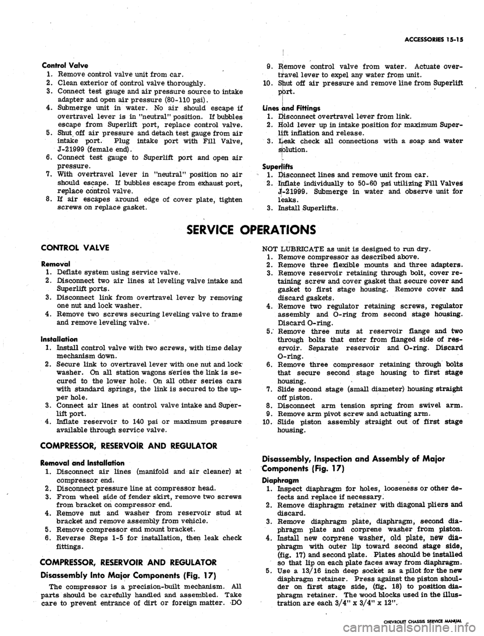
Control Valve
1.
Remove control valve unit from car.
2.
Clean exterior of control valve thoroughly.
3.
Connect test gauge and air pressure source to intake
adapter and open air pressure (80-110 psi).
4.
Submerge unit in water. No air should escape if
overtravel lever is in "neutral" position. If bubbles
escape from Superlift port, replace control valve.
5. Shut, off air pressure and detach test gauge from air
intake port. Plug intake port with Fill Valve,
J-21999 (female end).
6. Connect test gauge to Superlift port and open air
pressure.
7. With overtravel lever in "neutral" position no air
should escape. If bubbles escape from exhaust port,
replace control valve.
8. If air escapes around edge of cover plate, tighten
screws on replace gasket.
9. R(emove control valve from water. Actuate over-
travel lever to expel any water from unit.
10.
Sjiut off air pressure and remove line from Superlift
[
Lines and Fittings
1.
Eisconnect overtravel lever from link.
2.
Bold lever up in intake position for maximum Super-
lift inflation and release.
3.
iieak check all connections with a soap and water
splution.
[.
Superlifts
1.
disconnect lines and remove unit from car.
2.
ijiflate individually to 50-60 psi utilizing Fill Valves
jt-21999. Submerge in water and observe unit for
leaks.
3.
Install Superlifts.
SERVICE OPERATIONS
CONTROL VALVE
Removal
1.
Deflate system using service valve.
2.
Disconnect two air lines at leveling valve intake and
Superlift ports.
3.
Disconnect link from overtravel lever by removing
one nut and lock washer.
4.
Remove two screws securing leveling valve to frame
and remove leveling valve.
Installation
1.
Install control valve with two screws, with time delay
mechanism down.
2.
Secure link to overtravel lever with one nut and lock
washer. On all station wagons s'eries the link is se-
cured to the lower hole. On all other series cars
with standard springs, the link is secured to the up-
per hole.
3.
Connect air lines at control valve intake and Super-
lift port.
4.
Inflate reservoir to 140 psi or maximum pressure
available through service valve.
COMPRESSOR, RESERVOIR AND REGULATOR
Removal and Installation
1.
Disconnect air lines (manifold and air cleaner) at
compressor end;
2.
Disconnect pressure line at compressor head.
3.
From wheel side of fender skirt, remove two screws
from bracket on compressor end.
4.
Remove nut and washer from reservoir stud at
bracket and remove assembly from vehicle.
5. Remove compressor end mount bracket.
6. Reverse Steps 1-5 for installation, then leak check
fittings.
COMPRESSOR, RESERVOIR AND REGULATOR
Disassembly Into Major Components (Fig. 17)
The compressor is a precision-built mechanism. All
parts should be carefully handled and assembled. Take
care to prevent entrance of dirt or foreign matter. DO
NOT LUBRICATE as unit is designed to run dry.
1.
Remove compressor as described above.
2.
Remove three flexible mounts and three adapters.
3.
Remove reservoir retaining through bolt, cover re-
taining screw and cover gasket that secure cover and
gasket to first stage housing. Remove cover and
discard gaskets.
4.
Remove two regulator retaining screws, regulator
assembly and O-ring from second stage housing.
Discard O-ring.
5/ Remove three nuts at reservoir flange and two
through bolts that enter from flanged side of res-
ervoir. Separate reservoir and O-ring. Discard
O-ring.
6. Remove three compressor retaining through bolts
that secure second stage housing to first stage
housing.
7. Slide second stage (small diameter) housing straight
off piston.
8. Disconnect arm tension spring from swivel arm.
9. Remove arm pivot screw and actuating arm.
10.
Slide piston assembly straight out of first stage
housing.
Disassembly, Inspection and Assembly of Major
Components (Fig. 17)
Diaphragm
1.
Inspect diaphragm for holes, looseness or other de-
fects and replace if necessary.
2.
Remove diaphragm retainer with diagonal pliers and
discard.
3.
Remove diaphragm plate, diaphragm, second dia-
phragm plate and corprene washer from piston.
4.
Install new corprene washed, old plate, new dia-
phragm with outer lip toward second stage side,
(fig. 17) and second plate. Plates should be installed
so that lip on each plate faces away from diaphragm.
5. Use a 13/16 inch deep socket as a pilot for the new
diaphragm retainer. Press against the piston shoul-
der on first stage side, (fig. 18) to position dia-
phragm retainer. The wood blocks used in the illus-
tration are each 3/4" x 3/4" x 12".
CHEVROLET CHASSIS SERVICE MANUAL
Page 629 of 659
SPECIFICATIONS
2
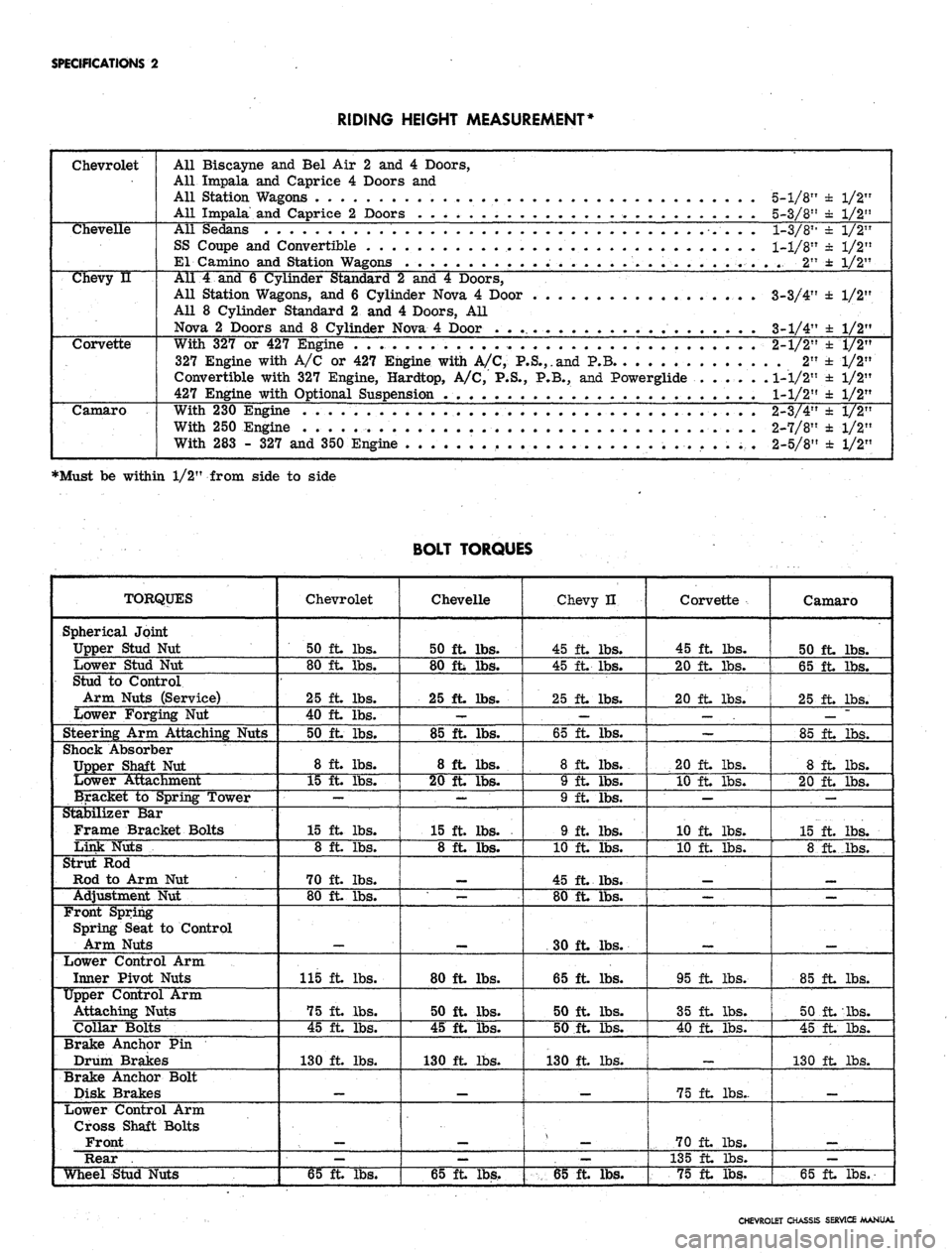
RIDING HEIGHT MEASUREMENT*
Chevrolet
All Biscayne
and Bel Air 2 and 4
Doors,
All Impala
and
Caprice
4
Doors
and
All Station Wagons
. . . .
All Impala
and
Caprice
2
Doors
. . . . .
5-1/8"
± 1/2"
5-3/8"
± 1/2"
Chevelle
All Sedans
SS Coupe
and
Convertible
El Camino
and
Station W*
1-3/811
± 1/2"
1-1/8"
± 1/2"
..
2" ± 1/2"
Chevy
u
All
4 and 6
Cylinder Standard
2 and 4
Doors,
All Station Wagons,
and 6
Cylinder Nova
4
Door
All
8
Cylinder Standard
2 and 4
Doors,
All
Nova
2
Doors
and 8
Cylinder Nova
4
Door
. . .
3-3/4'
3-1/4'
±
1/2'
±
1/2'
Corvette
With
327 or 427
Engine
. . . .
327 Engine with
A/C or 427
Engine with
A/C,
P.S.,.and
P.B
Convertible with
327
Engine, Hardtop,
A/C, P.S., P.B., and
Powerglide
427 Engine with Optional Suspension
.
2-1/2"
.
2"
1-1/2"
1-1/2"
±
1/2"
±1/2"
±
1/2"
±
1/2"
Camaro
With
230
Engine
..... . . .
With
250
Engine
.... ...
With
283 - 327 and
350 Engine
2-3/4"
2-7/8"
2-5/8"
± 1/2"
± 1/2"
± 1/2"
•Must be within 1/2" from side to side
BOLT TORQUES
TORQUES
Spherical Joint
Upper Stud
Nut
Lower Stud
Nut
Stud
to
Control
Arm Nuts (Service)
Lower Forging
Nut
Steering
Arm
Attaching Nuts
Shock Absorber
Upper Shaft
Nut
Lower Attachment
Bracket
to
Spring Tower
Stabilizer
Bar
Frame Bracket Bolts
Link Nuts
Strut
Rod
Rod
to Arm Nut
Adjustment
Nut
Front Spring
Spring Seat
to
Control
Arm Nuts
Lower Control
Arm
Inner Pivot Nuts
Upper Control Arm
Attaching Nuts
Collar Bolts
Brake Anchor Pin
Drum Brakes
Brake Anchor Bolt
Disk Brakes
Lower Control Arm
Cross Shaft Bolts
Front
Rear .
Wheel Stud Nuts
Chevrolet
50 ft. lbs.
80 ft lbs.
25 ft. lbs.
40 ft. lbs.
50 ft. lbs.
8 ft. lbs.
15 ft. lbs.
—
15 ft lbs.
8 ft. lbs.
70 ft lbs.
80 ft lbs.
115 ft lbs.
75 ft lbs.
45 ft lbs.
130 ft lbs.
—
65 ft lbs.
Chevelle
50 ft lbs.
80 ft lbs.
25 ft. lbs.
—
85 ft lbs.
8 ft lbs.
20 ft lbs.
—
15 ft lbs.
8 ft lbs.
—
80 ft lbs.
50 ft. lbs.
45 ft. lbs.
130 ft lbs.
—
65 ft lbs.
Chevy H
45 ft lbs.
45 ft lbs.
25 ft lbs.
—
65 ft. lbs.
8 ft lbs.
9 ft lbs.
9 ft. lbs.
9 ft. lbs.
10 ft. lbs.
45 ft lbs.
80 ft lbs.
30 ft lbs.
65 ft lbs.
50 ft. lbs.
50 ft lbs.
130 ft lbs.
_
—
65 ft lbs.
Corvette
45 ft lbs.
20 ft lbs.
20 ft lbs.
—
20 ft lbs.
10 ft lbs.
—
10 ft lbs.
10 ft. lbs.
—
95 ft lbs.
35 ft lbs.
40 ft lbs.
75 ft lbs..
70 ft lbs.
135 ft lbs.
75 ft lbs.
Camaro
50 ft lbs.
65 ft lbs.
25 ft lbs.
—
85 ft lbs.
8 ft lbs.
20 ft lbs.
.
—
15 ft. lbs.
8 ft._lbs.
_
85 ft lbs.
50 ft lbs.
45 ft lbs.
130 ft lbs.
_
—
65 ft lbs.
CHEVROLET CHASSIS SERVICE MANUAL
Page 648 of 659
SPECIFICATIONS
21
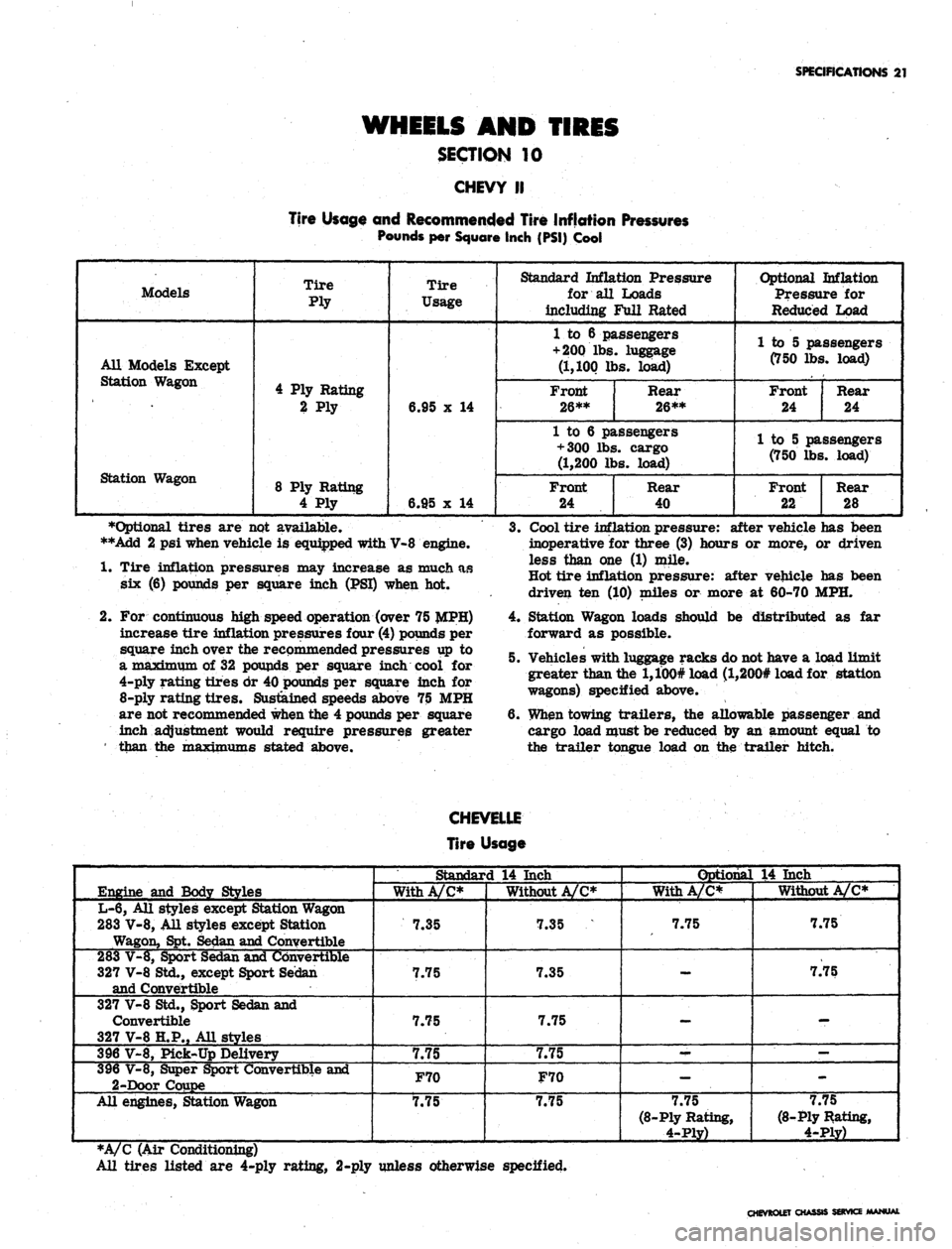
WHEELS AND TIRES
SECTION 10
CHEVY II
Tire Usage and Recommended Tire Inflation Pressures
Pounds per Square Inch (PSI) Cool
Models
All Models Except
Station Wagon
Station Wagon
Tire
Ply
4 Ply Rating
2 Ply
8 Ply Rating
4 Ply
Tire
Usage
6.95 x 14
6.95 x 14
Standard Inflation Pressure
for all Loads
including Full Rated
1 to 6 passengers
+ 200
lbs. luggage
(1,100 lbs. load)
Front
26**
Rear
26**
1 to 6 passengers
+ 300 lbs. cargo
(1,200 lbs. load)
Front
24
Rear
40
Optional Inflation
Pressure for
Reduced Load
1 to 5 passengers
(750 lbs. load)
Front
24
Rear
24
1 to 5 passengers
(750 lbs. load)
Front
22
Rear
28
•Optional tires are not available.
**Add 2 psi when vehicle is equipped with V-8 engine.
1.
Tire inflation pressures may increase as much as
six (6) pounds per square inch (PSI) when hot.
2.
For continuous high speed operation (over 75
increase tire inflation pressures four (4) pounds per
square inch over the recommended pressures up to
a maximum of 32 pounds per square inch cool for
4-ply rating tires dr 40 pounds per square inch for
8-ply
rating tires. Sustained speeds above 75 MPH
are not recommended when the 4 pounds per square
inch adjustment would require pressures greater
' than the TpaxiTP^Tns stated above.
3.
Cool tire inflation pressure: after vehicle has been
inoperative for three (3) hours or more, or driven
less than one (1) mile.
Hot tire inflation pressure: after vehicle has been
driven ten (10) miles or more at 60-70 MPH.
4.
Station Wagon loads should be distributed as far
forward as possible.
5. Vehicles with luggage racks do not have a load limit
greater than the l,100# load (l,200# load for station
wagons) specified above.
6. When towing trailers, the allowable passenger and
cargo load must be reduced by an amount equal to
the trailer tongue load on the trailer hitch.
CHEVELLE
Tire Usage
Engine and Body Styles
L-6, All styles except Station Wagon
283 V-8, All styles except Station
Wagon, Spt. Sedan and Convertible
283 V-8, Sport Sedan and Convertible
327 V-8 Std., except Sport Sedan
and Convertible
327 V-8 Std., Sport Sedan and
Convertible
327 V-8 H.P., All styles
396 V-8, Pick-Up Delivery
396 V-8, Super Sport Convertible and
2-Door Coupe
All engines, Station Wagon
Standard 14 Inch
With A/C*
7.35
7.75
7.75
7.75
F70
7.75
Without A/C*
7.35
7.35
7.75
7.75
F70
7.75
Optional 14 Inch
With A/C*
7.75
—
-
--
-
7.75
(8-Ply Rating,
4-Ply)
Without A/C*
7.75
7.75
-
—
-
7.75
(8-Ply Rating,
4-Ply)
*A/C (Air Conditioning)
All tires listed are 4-ply rating, 2-ply unless otherwise specified.
CHEVROLET CHASSIS SERVICE MANW
Page 649 of 659
SPECIFICATIONS
22
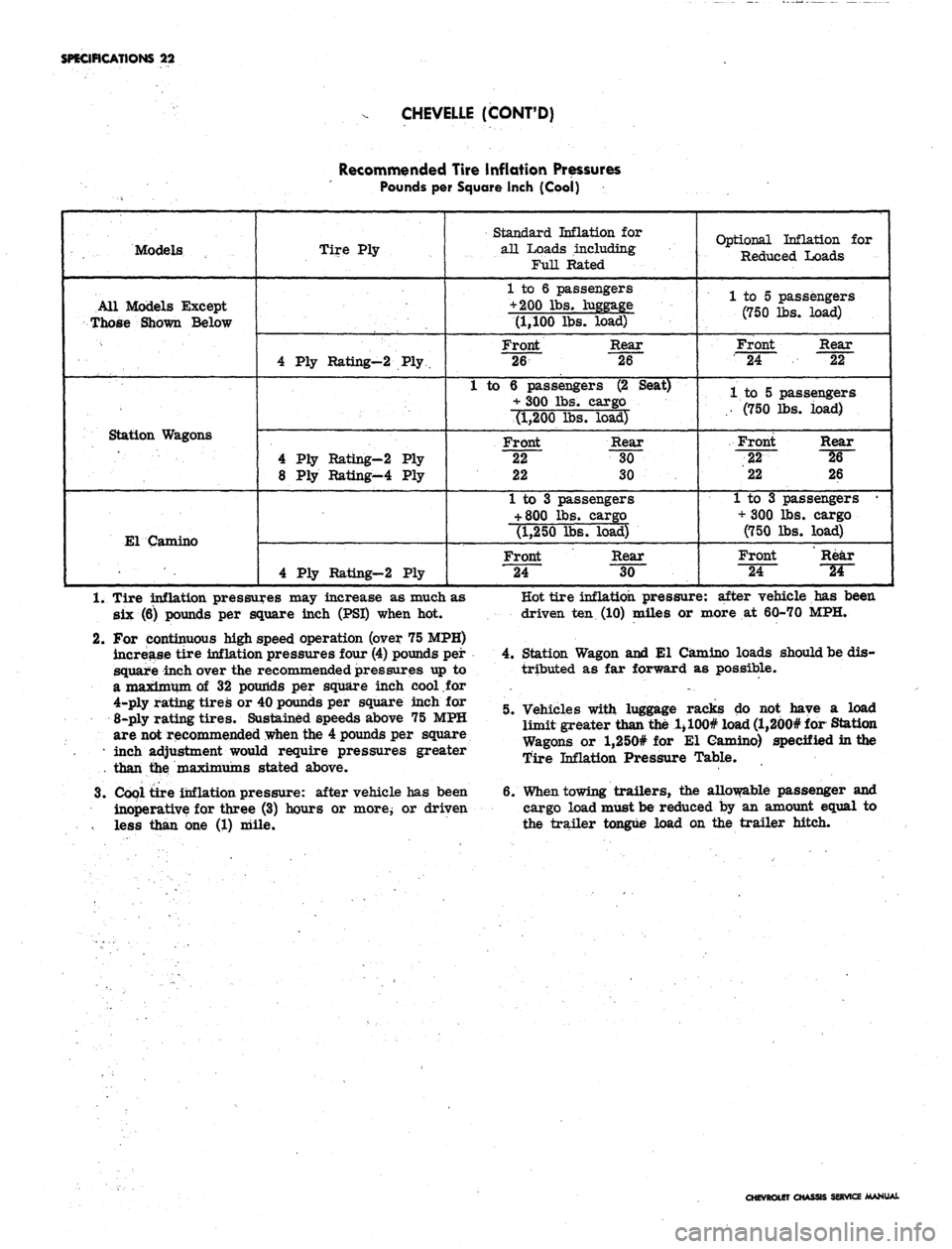
CHEVELLE (CONT'D)
Recommended Tire inflation Pressures
Pounds per Square Inch (Cool)
Models
All Models Except
Those Shown Below
Station Wagons
El Camino
Tire Ply
4 Ply Rating-2 Ply
4 Ply Rating-2 Ply
8 Ply Rating-4 Ply
4 Ply Rating-2 Ply
Standard Inflation for
all Loads including
FuH Rated
1 to 6 passengers
+ 200 lbs. luggage
(1,100 lbs. load)
Front Rear
26 26
1 to 6 passengers (2 Seat)
+ 300 lbs. cargo
(1,200 lbs. load)
Front Rear
22 30
22 30
1 to 3 passengers
+
800 lbs. cargo
(1,250 lbs. load)
Front Rear
24 30
Optional Inflation for
Reduced Loads
1 to 5 passengers
(750 lbs. load)
Front Rear
24 22
1 to 5 passengers
.. (750 lbs. load)
Front Rear
22 ^6~
22 26
1 to 3 passengers •
+ 300 lbs. cargo
(750 lbs. load)
Front Rear
"24~
~W~
1.
Tire inflation pressures may increase as much as
six (6) pounds per square inch (PSI) when hot.
2.
For continuous high speed operation (over 75 MPH)
increase tire inflation pressures four (4) pounds per
square inch over the recommended pressures up to
a maximum of 32 pounds per square inch cool for
4-ply rating tires or 40 pounds per square inch for
8-ply rating tires. Sustained speeds above 75 MPH
are not recommended when the 4 pounds per square
• inch adjustment would require pressures greater
than the maximums stated above.
3.
Cool tire inflation pressure: after vehicle has been
inoperative for three (3) hours or more; or driven
less than one (1) mile.
Hot tire inflation pressure: after vehicle has been
driven ten (10) miles or more at 60-70 MPH.
4.
Station Wagon and El Camino loads should be dis-
tributed as far forward as possible.
5. Vehicles with luggage racks do not have a load
limit greater than the 1 > 100# load (l,200# for Station
Wagons or l,250# for El Camino) specified in the
Tire Inflation Pressure Table.
6. When towing trailers, the allowable passenger and
cargo load must be reduced by an amount equal to
the trailer tongue load on the trailer hitch.
OLETO
SERVICE MANUAL
Page 650 of 659
SPECIFICATIONS 23
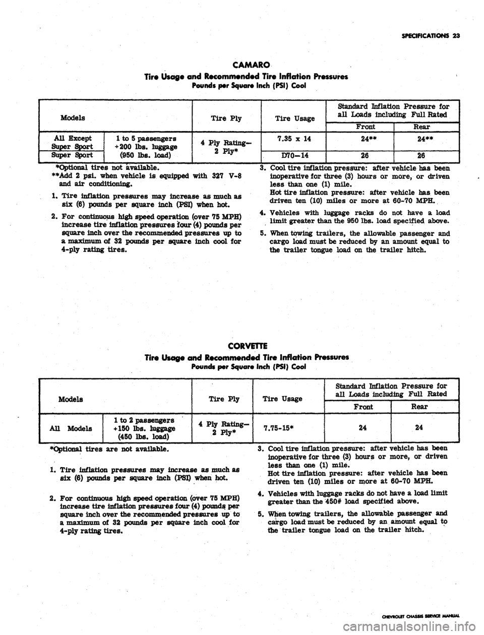
CAMARO
Tire Usage and Recommended Tire Inflation Pressures
Pounds per Square Inch (PSI) Cool
Models
All Except
Super Sport
Super Sport
1 to 5 passengers
+ 200
lbs. luggage
(950 lbs. load)
Tire Ply
4 Ply Rating-
2 Ply*
Tire Usage
7.35 x 14
D70-14
Standard Inflation Pressure for
all Loads including Full Rated
Front
24**
26
Rear
24**
26
•Optional tires not available.
**Add 2 psi. when vehicle is equipped with 327 V-8
and air conditioning*
1.
Tire inflation pressures may increase as much as
six (6) pounds per square inch (PSI) when hot.
2.
For continuous high speed operation (over 75 MPH)
increase tire inflation pressures four
(4)
pounds per
square inch over the recommended pressures up to
a maximum of 32 pounds per square inch cool for
4-ply rating tires.
3.
Cool tire inflation pressure: after vehicle has been
inoperative for three (3) hours or more, or driven
less than one (1) mile.
Hot tire inflation pressure: after vehicle has been
driven ten (10) miles or more at 60-70 MPH.
4.
Vehicles with luggage racks do not have a load
limit greater than the 950 lbs. load specified above.
5. When towing trailers, the allowable passenger and
cargo load must be reduced by an amount equal to
the trailer tongue load on the trailer hitch.
CORVETTE
Tire Usage and Recommended Tire Inflation Pressures
Pounds per Square Inch (PSI) Cool
Models
All Models
1 to 2 passengers
+150 lbs. luggage
(450 lbs. load)
Tire Ply
4 Ply Rating-
2 Ply*
Tire Usage
7.75-15*
Standard Inflation Pressure for
all Loads including Full Rated
Front
24
Rear
24
•Optional tires are not available.
1.
Tire inflation pressures may increase as much as
six (6) pounds per square inch (PSI) when hot.
2.
For continuous high speed operation (over 75 MPH)
increase tire inflation pressures four
(4)
pounds per
square inch over the recommended pressures up to
a maximum of 32 pounds per square inch cool for
4-ply rating tires.
3.
Cool tire inflation pressure: after vehicle has been
inoperative for three (3) hours or more, or driven
less than one (1) mile.
Hot tire inflation pressure: after vehicle has been
driven ten (10) miles or more at 60-70 MPH.
4.
Vehicles with luggage racks do not have a load limit
greater than the 450# load specified above.
5. When towing trailers, the allowable passenger and
cargo load must be reduced by an amount equal to
the trailer tongue load on the trailer hitch.
CHEVROLET CHASSIS SERVICE MANUAL
Page 651 of 659
SPECIFICATIONS 24
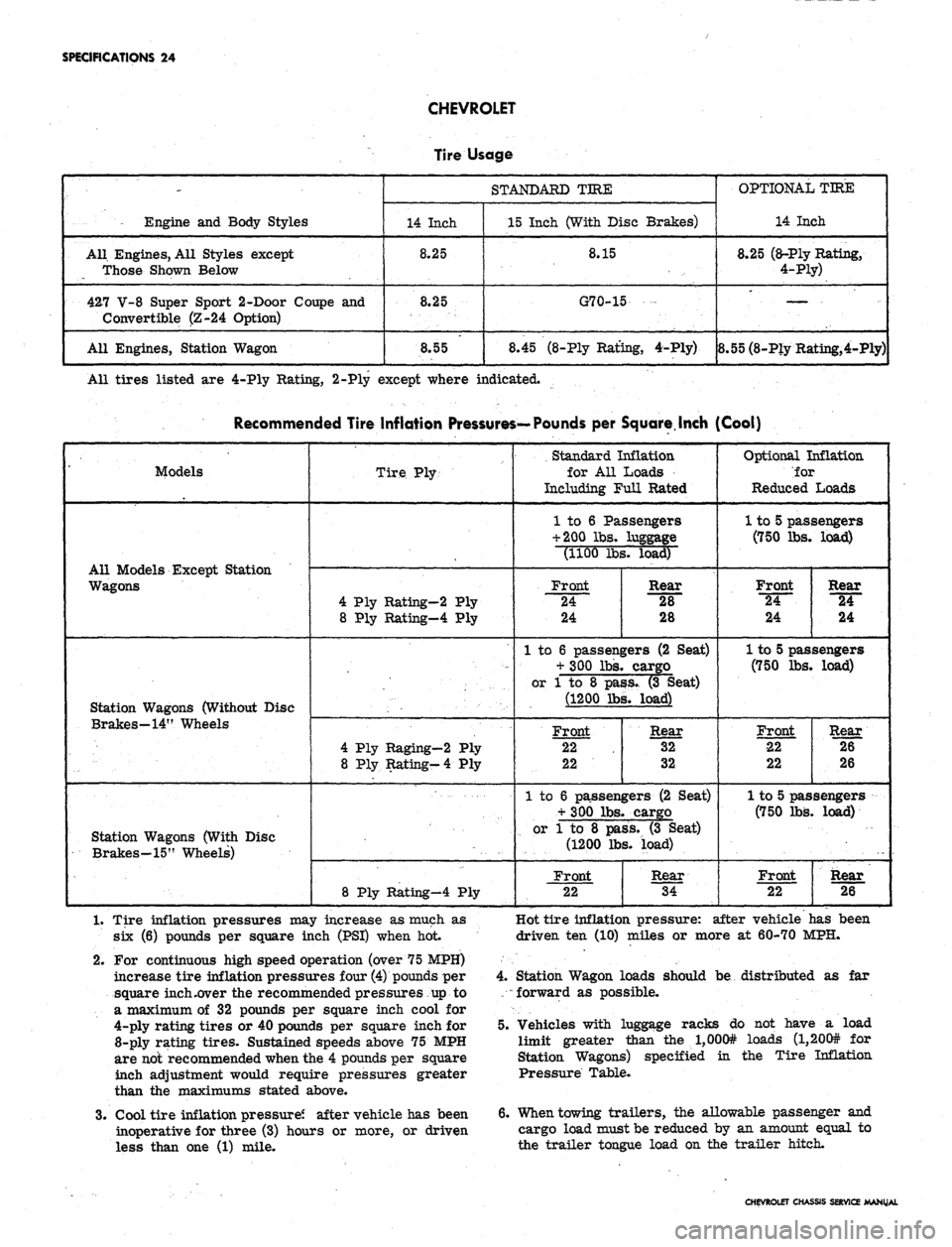
CHEVROLET
Engine and Body Styles
All. Engines, All Styles except
Those Shown Below
427 V-8 Super Sport 2-Door Coupe and
Convertible (Z-24 Option)
All Engines, Station Wagon
Tire
14 Inch
8.25
8.25
8.55
Usage
STANDARD TIRE
15 Inch (With Disc
8.15
G70-15
8.45 (8-Ply Rating,
Brakes)
4-Ply)
OPTIONAL TIRE
14 Inch
8.25 (a-Ply Rating,
4-Ply)
. —. ...
8.55 (8-Ply Rating,4-Ply)
All tires listed are 4-Ply Rating, 2-Ply except where indicated.
Recommended Tire Inflation Pressures—Pounds per Square.Inch (Cool)
' Models
All Models Except Station
Wagons
Station Wagons (Without Disc
Brakes—14" Wheels
Station Wagons (With Disc
Brakes-15" Wheels)
Tire Ply-
4 Ply Rating-2 Ply
8 Ply Rating-4 Ply
4 Ply Raging—2 Ply
8 Ply Rating-4 Ply
8 Ply Rating-4 Ply
Standard Inflation
for All Loads
Including Full Rated
1 to 6 Passengers
+ 200 lbs. luggage
(1100 lbs. load)
Front
24
24
Rear
28
28
1 to 6 passengers (2 Seat)
+ 300 lbs. cargo
or 1 to 8 pass. (3 Seat)
(1200 lbs. load)
Front
22
22
Rear
32
32
1 to 6 passengers (2 Seat)
+ 300 lbs. cargo
or 1 to 8 pass. (3 Seat)
(1200 lbs. load)
Front
22
Rear
34
Optional Inflation
ior
Reduced Loads
1 to 5 passengers
(750 lbs. load)
Front
"24~
24
Rear
24
24
1 to 5 passengers
(750 lbs. load)
Front
22
22
Rear
26
26
1 to 5 passengers
(750 lbs. load)
Front
22
Rear
26
1.
Tire inflation pressures may increase as much as
six (6) pounds per square inch (PSI) when hot
2.
For continuous high speed operation (over 75 MPH)
increase tire inflation pressures four (4) pounds per
square inch .over the recommended pressures up to
a maximum of 32 pounds per square inch cool for
4-ply rating tires or 40 pounds per square inch for
8-ply rating tires. Sustained speeds above 75 MPH
are not recommended when the 4 pounds per square
inch adjustment would require pressures greater
than the maximums stated above.
3.
Cool tire inflation pressure? after vehicle has been
inoperative for three (3) hours or more, or driven
less than one (1) mile.
Hot tire inflation pressure: after vehicle has been
driven ten (10) miles or more at 60-70 MPH.
4.
Station Wagon loads should be distributed as far
forward as possible.
5. Vehicles with luggage racks do not have a load
limit greater than the l,000# loads (l,200# for
Station Wagons) specified in the Tire Inflation
Pressure Table.
6. When towing trailers, the allowable passenger and
cargo load must be reduced by an amount equal to
the trailer tongue load on the trailer hitch.
CHEVROLET CHASSIS SERVICE MANUAL