tow CHEVROLET CAMARO 1967 1.G Chassis Manual PDF
[x] Cancel search | Manufacturer: CHEVROLET, Model Year: 1967, Model line: CAMARO, Model: CHEVROLET CAMARO 1967 1.GPages: 659, PDF Size: 114.24 MB
Page 461 of 659
STEERING 9-21
Fig.
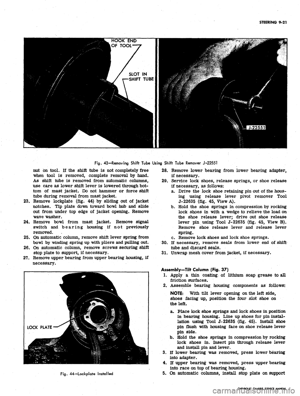
43-Removing Shift Tube Using Shift Tube Remover J-22551
nut on tool. If the shift tube is not completely free
when tool is removed, complete removal by hand.
As shift tube is removed from automatic columns,
use care as lower shift lever is lowered through bot-
tom of mast jacket. Do not hammer or force shift
tube during removal from mast jacket.
23.
Remove lockplate (fig. 44) by sliding out of jacket
notches. Tip plate down toward bowl hub and slide
out from under top edge of jacket opening. Remove
wave washer.
24.
Remove bowl from mast jacket. Remove signal
switch and bearing housing if not previously
removed.
25.
On automatic column, remove shift lever spring from
bowl by winding spring up with pliers and pulling out.
26.
On automatic column, remove screws securing shift
stop plate to support, if necessary.
27.
Remove upper bearing from upper bearing housing, if
necessary.
Fig.
44—Lockplate Installed
28.
Remove lower bearing from lower bearing adapter,
if necessary.
29.
Service lock shoes, release springs, or shoe release
if necessary, as follows:
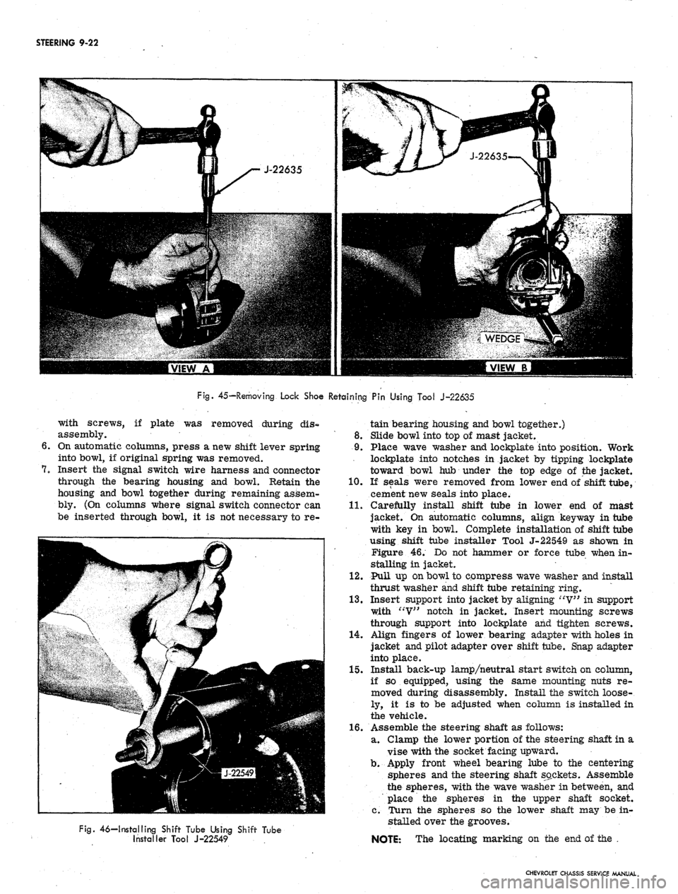
a. Drive the lock shoe retaining pin out of the hous-
ing using release lever pivot remover Tool
J-22635 (fig. 45, View A).
b.
Hold the shoe springs in compression by rocking
lock shoes in with a wedge to relieve the load on
the shoe release lever; drive out shoe release
lever pin using Tool J-22635 (fig. 45, View B).
Remove shoe release lever and release lever
spring.
c. Remove lock shoes and lock shoe springs.
30.
If necessary, remove seals from lower end of shift-
tube and discard seals.
31.
Unwrap mesh cover from jacket, if necessary.
Assembly-Tilt Column (Fig. 37)
1.
Apply a thin coating of lithium soap grease to all
friction surfaces.
2.
Assemble bearing housing components as follows:
NOTE:
With tilt lever opening on the left side,
shoes facing up, position the four slot shoe on
the left.
a. Place lock shoe springs and lock shoes in position
in bearing housing. Line up shoes for pin instal-
lation using Tool J-22635 (fig. 45). Install shoe
pin flush with housing face on shoe release lever
pin side.
b.
Hold the shoe springs in compression by rocking
lock shoes in. Insert pin through release lever
and install pin and lever.
3.
If lower bearing was removed, press lower bearing
into adapter.
4.
If upper bearing was removed, press upper bearing
into race on top of bearing housing.
5. On automatic columns, install stop plate on support
CHEVROLET CHASSIS SERVICE MANUAL
Page 462 of 659
STEERING 9-22
Fig.
45—Removing Lock Shoe Retaining Pin Using Tool J-22635
with screws, if plate was removed during dis-
assembly.
On automatic columns, press a new shift lever spring
into bowl, if original spring was removed.
Insert the signal switch wire harness and connector
through the bearing housing and bowl. Retain the
housing and bowl together during remaining assem-
bly. (On columns where signal switch connector can
be inserted through bowl, it is not necessary to re-
Fig.
46—Installing Shift Tube Using Shift Tube
Installer Tool J-22549
tain bearing housing and bowl together.)
8. Slide bowl into top of mast jacket.
9. Place wave washer and lockplate into position. Work
lockplate into notches in jacket by tipping lockplate
toward bowl hub under the top edge of the jacket.
10.
If seals were removed from lower end of shift tube,
cement new seals into place.
11.
Carefully install shift tube in lower end of mast
jacket. On automatic columns, align key way in tube
with key in bowl. Complete installation of shift tube
using shift tube installer Tool J-22549 as shown in
Figure 46. Do not hammer or force tube when in-
stalling in jacket.
12.
Pull up on bowl to compress wave washer and install
thrust washer and shift tube retaining ring.
13.
Insert support into jacket by aligning "V" in support
with "V" notch in jacket. Insert mounting screws
through support into lockpiate and tighten screws.
14.
Align fingers of lower bearing adapter with holes in
jacket and pilot adapter over shift tube. Snap adapter
into place.
15.
Install back-up lamp/neutral start switch on column,
if so equipped, using the same mounting nuts re-
moved during disassembly. Install the switch loose-
ly, it is to be adjusted when column is installed in
the vehicle.
16.
Assemble the steering shaft as follows:
a. Clamp the lower portion of the steering shaft in a
vise with the socket facing upward.
b.
Apply front wheel bearing lube to the centering
spheres and the steering shaft sockets. Assemble
the spheres, with the wave washer in between, and
place the spheres in the upper shaft socket.
c. Turn the spheres so the lower shaft may be in-
stalled over the grooves.
NOTE: The locating marking on the end of the .
CHEVROLET CHASSIS SERVICE MANUAL
Page 481 of 659
SECTION 10
WHEELS AND TIRES
INDEX
Page
General Description
10-1
Maintenance
and
Adjustments
.............. 10—1
Tires
10-1
Pressures . 10-1
Inspection 10-1
Wear 10-1
Rotation 10-4
Noise 10-4
Cleaning 10-4
Change (W/Wheels) 10-4
Wheels 10-5
Static Balancing (w/Tire) 10-5
Page
Dynamic Balancing (w/Tire) . 10-5
Run Out (w/o Tire) 10-5
Cleaning 10-5
Service Operations 10-5
Tires 10-5
Removal 10-5
Installation 10-5
Repair 10^6
Wheels . 10-6
Valve Assembly 10-6
Repair (Rim) 10-7
GENERAL DESCRIPTION
WHEELS
Chevrolet, Chevelle, Camaro, Chevy n, and Corvette
are base equipped with welded steel wheels. Five studs
with nuts fasten each wheel to the front hub or rear axle
flange. Disc brake equipped vehicles (except Chevrolet
and Corvette) require special 14 inch diameter wheels
with a revised design for clearance, Chevrolet disc brake
equipped vehicles have 15 in. diameter wheels as do all
Corvettes.
Chevrolet station wagons, Chevelle Super Sport 396,
Corvette and Camaro Super Sport 350 are base equipped
with 6 in. width wheels. All other vehicles have 5 in.
width wheels, except Chevy n 100, 300 and 500 Series
Sedans, which have 4 in. width wheels.
Do not install 6 inch width wheels or snow chains on
Chevrolets equipped with rear fender skirts.
TIRES
The factory installed tires on Chevrolet passenger
cars are selected to provide the best all around tire
performance for all normal operation. They are de-
signed to operate satisfactorily with loads up to and in-
cluding the specified full rated load capacity of the
automobile when inflated as recommended in the Vehicle
Capacity Rating and Recommended Tire Inflation Pres-
sures Table (see Specifications).
Optional Oversize and 8-Ply Rating Tires
{Chevrolet and Chevelle Only)
Oversize or 8-ply rating tires are not necessary on
passenger cars for normal requirements. However, an
extra margin of tire service is available when these
options are used at loads up to and including full rated
load.
Optional oversize 4-ply rating and/or 8-ply rating
tires are available on models as indicated in the Tire
Usage Chart (see Specifications). On some models (ex-
ample—Station Wagon), space limitations do not permit
the use of a larger size tire; hence, the 8-ply rating
tire is an available option.
In either case, these tires are applicable to extended
operation at or near full rated load or for trailer towing
when an extra margin of tire service is desired. How-
ever, use of a larger tire or an 8-ply rating tire should
not be construed as permitting an increase in the full
rated vehicle load (see Specifications).
MAINTENANCE AND ADJUSTMENTS
TIRES
Inflation Pressures
To ensure the proper tire inflation pressure for the
owners particular requirements follow the recommenda-
tions in the Vehicle Capacity Rating and Recommended
Tire Inflation Pressures Table (seeSpecifications). Keep
tires properly inflated, and check inflation pressures
periodically. This will ensure the best tire life and riding
comfort, over the full range of driving conditions.
Inspection
Every few thousand miles and at each lubrication, tires
should be checked for sharp objects or stones in the
tread. H tire is punctured, it should be repaired using
one of several repair kits available through tire manu-
facturers1 outlets.
Wear
Misalignment
This is wear due to excessive toe-in or toe-out. In
CHEVROLET CHASSIS SERVICE MANUAL
Page 499 of 659
CHASSIS SHEET METAL 11-12
GENERAL DESCRIPTION
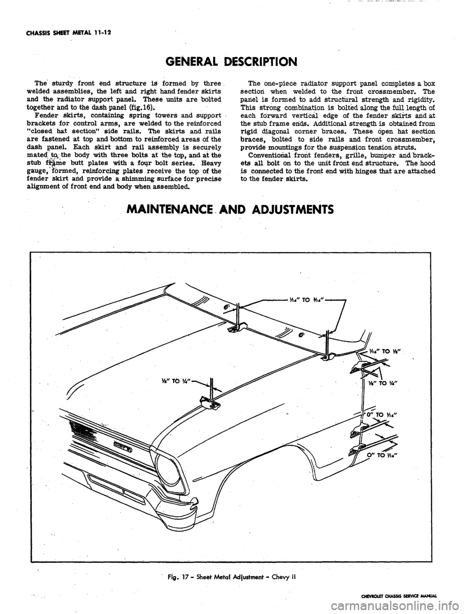
The sturdy front end structure is formed by three
welded assemblies, the left and right hand fender skirts
and the radiator support panel. These units are bolted
together and to the dash panel (fig.
16).
Fender skirts, containing spring towers and support
brackets for control arms, are welded to the reinforced
"closed hat section" side rails. The skirts and rails
are fastened at top and bottom to reinforced areas of the
dash panel. Each skirt and rail assembly is securely
mated ta the body with three bolts at the top, and at the
stub fr|.me butt plates with a four bolt series. Heavy
gauge, formed, reinforcing plates receive the top of the
fender skirt and provide a shimming surface for precise
alignment of front end and body when assembled.
The one-piece radiator support panel completes a box
section when welded to the front crossmember. The
panel is formed to add structural strength and rigidity.
This strong combination is bolted along the full length of
each forward vertical edge of the fender skirts and at
the stub frame ends. Additional strength is obtained from
rigid diagonal corner braces. These open hat section
braces, bolted to side rails and front crossmember,
provide mountings for the suspension tension struts.
Conventional front fenders, grille, bumper and brack-
ets all bolt on to the unit front end structure. The hood
is connected to the front end with hinges that are attached
to the fender skirts.
MAINTENANCE AND ADJUSTMENTS
" TO •/•"
Fig.
17 - Sheet Metd Adjustment - Chevy II
CHEVROLET CHASSIS SERVICE MANUAL
Page 501 of 659
CHASSIS SHEET METAL 11-14
location is shimmed; thus keeping the fender mount-
ing bolts from crushing in the fender mounting
flange.
If shimming is done without the fenders being disas-
asembled, it is suggested that fender mounting bolts
rearward of radiator support be loosened while shims
are inserted and sheet metal fit is checked. Tighten
shimmed mounting bolts first, then all others.
COMPONENT PART REPLACEMENT
BATTERY TRAY (FIG. 21)
Removal
1.
Disconnect battery cables.
2.
Remove screw retaining battery hold down clamp.
3.
Remove battery from vehicle.
4.
Remove screws retaining tray assembly to fender
skirt and support, and remove tray from vehicle.
Installation
Reverse removal procedure.
RADIATOR SUPPORT (FIG. 22)
Removal
1.
Remove grille and related components (Section 13).
Remove battery tray as outlined in this section.
Remove shroud attaching screws and remove shroud
if vehicle is so equipped.
Remove horn relay, horns, voltage regulator, and
wiring harness from radiator support.
Remove shroud and radiator (Section 13)o
Remove screws attaching radiator support to frame,
skirts,
fenders.
Remove radiator support from vehicle (fig. 23).
Installation
1.
Position radiator support in vehicle; align mounting
screw and bolt holes with drift punch.
Install screws and bolts loosely until all are started,
then tighten.
3.
Complete installation following removal procedure in
reverse order. Refer to torque specifications at rear
of manual for correct torque values.
4.
Aim headlamps as outlined in Section 12.
FRONT FENDER ASSEMBLY
Removal
1*
Remove headlamp dooro
2.
Open hood and remove screws joining fender top
2.
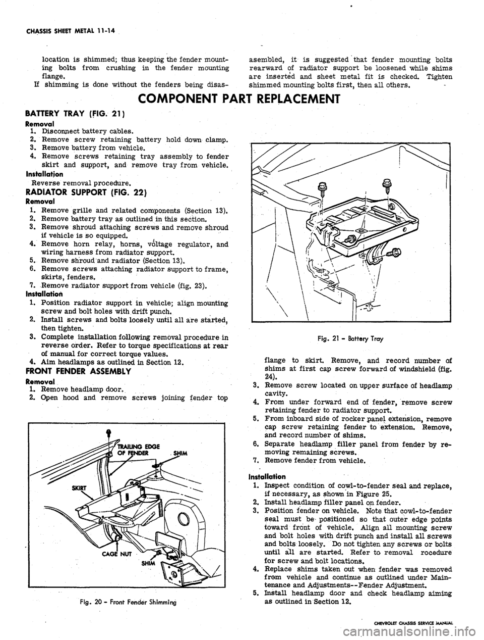
Fig. 20 - Front Fender Shimming
Fig.
21 - Battery Tray
flange to skirt. Remove, and record number of
shims at first cap screw forward of windshield (fig.
24).
3.
Remove screw located on upper surface of headlamp
cavity.
4.
From under forward end of fender, remove screw
retaining fender to radiator support.
5.
From inboard side of rocker panel extension, remove
cap screw retaining fender to extension. Remove,
and record number of shims.
6. Separate headlamp filler panel from fender by re-
moving remaining screws.
7.
Remove fender from vehicle.
Installation
1.
Inspect condition of cowl-to-fender seal and replace,
if necessary, as shown in Figure 25.
2.
Install headlamp filler panel on fender.
3.
Position fender on vehicle. Note that eowl-to-fender
seal must be positioned so that outer edge points
toward front of vehicle. Align all mounting screw
and bolt holes with drift punch and install all screws
and bolts loosely. Do not tighten any screws or bolts
until all are started. Refer to removal rocedure
for screw and bolt locations.
4.
Replace shims taken out when fender was removed
from vehicle and continue as outlined under Main-
tenance and Adjustments—Fender Adjustment.
5.
Install headlamp door and cheek headlamp aiming
as outlined in Section 12.
CHEVROLET CHASSIS SERVICE MANUAL
Page 521 of 659
ELECTRICAL-BODY AND CHASSIS 12-9
Fig.
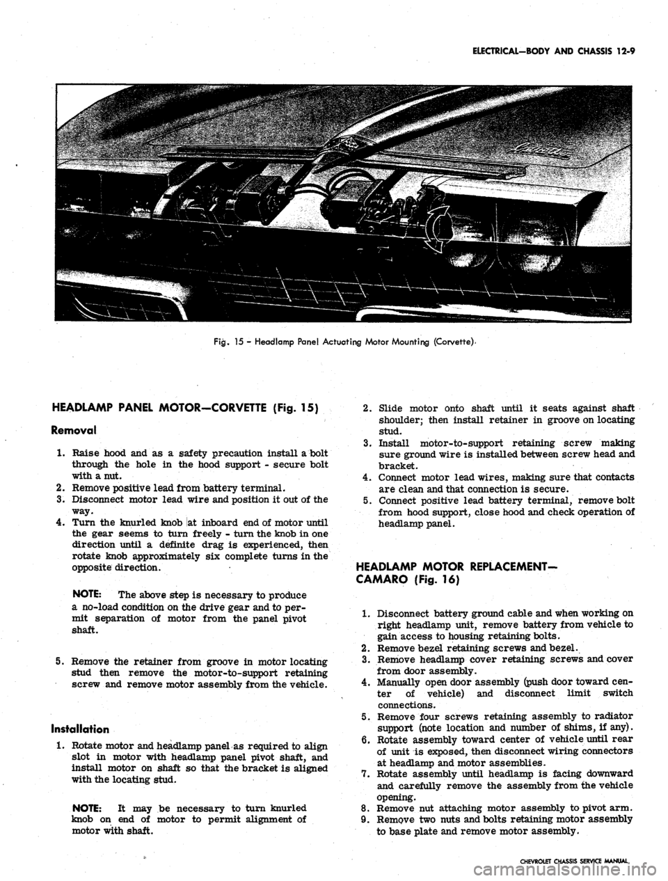
15 - Headlamp Panel Actuating Motor Mounting (Corvette)'
HEADLAMP PANEL MOTOR-CORVETTE (Fig. 15)
Removal
1.
Raise hood and as a safety precaution install a bolt
through the hole in the hood support - secure bolt
with a nut.
2.
Remove positive lead from battery terminal.
3.
Disconnect motor lead wire and position it out of the
way.
4.
Turn the knurled knob at inboard end of motor until
the gear seems to turrj freely - turn the knob in one
direction until a definite drag is experienced, then
rotate knob approximately six complete turns in the
opposite direction.
NOTE:
The above step is necessary to produce
a no-load condition on the drive gear and to per-
mit separation of motor from the panel pivot
shaft.
5. Remove the retainer from groove in motor locating
stud then remove the motor-to-support retaining
screw and remove motor assembly from the vehicle.
Installation
1.
Rotate motor and headlamp panel as required to align
slot in motor with headlamp panel pivot shaft, and
install motor on shaft so that the bracket is aligned
with the locating stud.
NOTE:
It may be necessary to turn knurled
knob on end of motor to permit alignment of
motor with shaft.
Slide motor onto shaft until it seats against shaft
shoulder; then install retainer in groove on locating
stud.
Install motor-to-support retaining screw making
sure ground wire is installed between screw head and
bracket.
Connect motor lead wires, making sure that contacts
are clean and that connection is secure.
Connect positive lead battery terminal, remove bolt
from hood support, close hood and check operation of
headlamp panel.
HEADLAMP MOTOR REPLACEMENT-
CAMARO (Fig. 16)
1.
Disconnect battery ground cable and when working on
right headlamp unit, remove battery from vehicle to
gain access to housing retaining bolts.
2.
Remove bezel retaining screws and bezel.
3.
Remove headlamp cover retaining screws and cover
from door assembly.
4.
Manually open door assembly (push door toward cen-
ter of vehicle) and disconnect limit switch
connections.
5. Remove four screws retaining assembly to radiator
support (note location and number of shims, if any).
6. Rotate assembly toward center of vehicle until rear
of unit is exposed, then disconnect wiring connectors
at headlamp and motor assemblies.
7. Rotate assembly until headlamp is facing downward
and carefully remove the assembly from the vehicle
opening.
8. Remove nut attaching motor assembly to pivot arm.
9. Remove two nuts and bolts retaining motor assembly
to base plate and remove motor assembly.
CHEVROLET CHASSIS SERVICE MANUAL
Page 564 of 659
ELECTRICAL-BODY AND CHASSIS 12-52
GEAR MECHANISM
NOT IN PARK
RELAY SWITCH ATTACHING SCREW
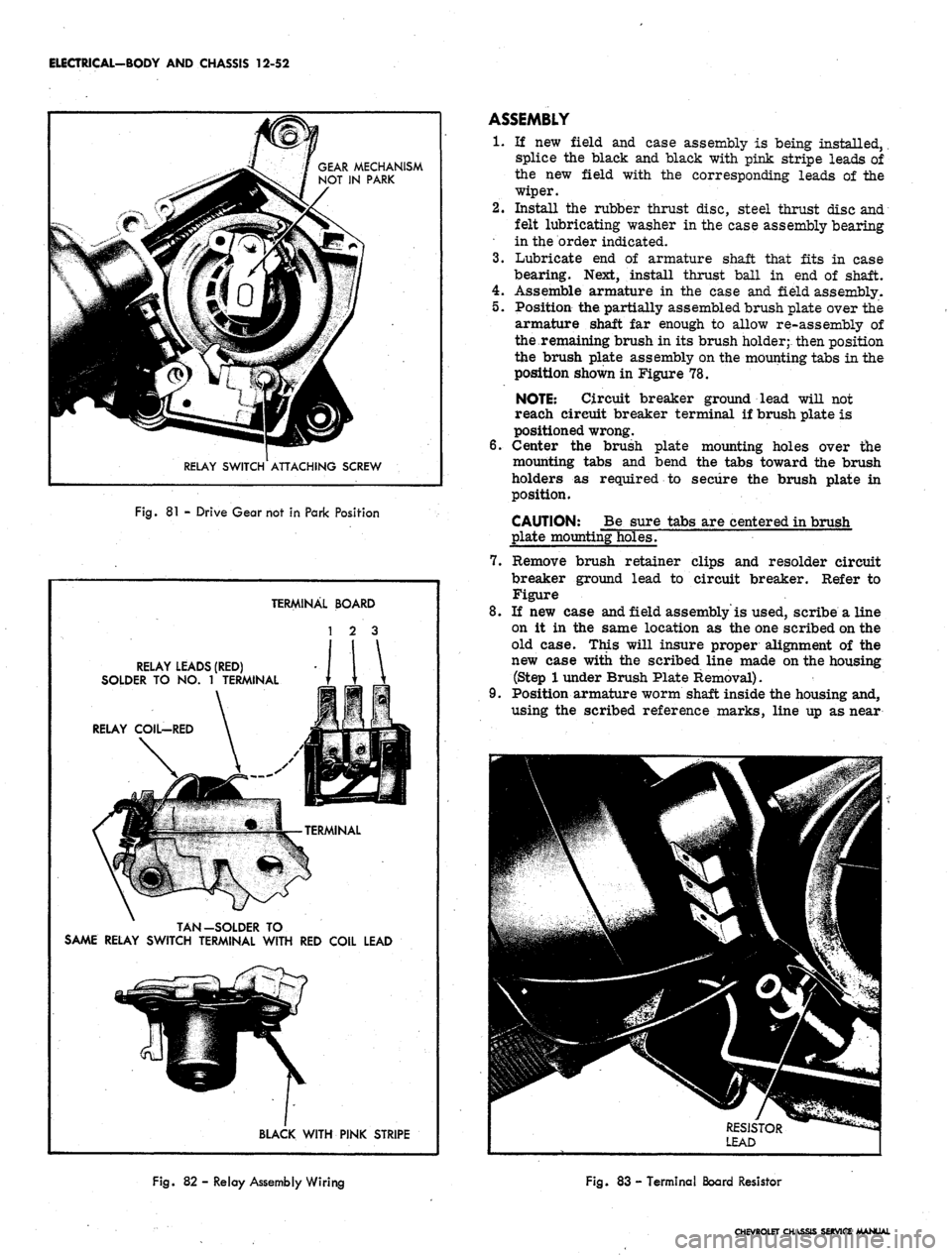
Fig.
81 -
Drive Gear not
in
Park Position
TERMINAL BOARD
1 2 3
RELAY LEADS (RED)
SOLDER TO NO. 1 TERMINAL
RELAY
COIL-RED
TAN-SOLDER TO
SAME RELAY SWITCH TERMINAL WITH RED COIL LEAD
BLACK WITH PINK STRIPE
ASSEMBLY
1.
If new field and case assembly is being installed,
splice the black and black with pink stripe leads of
the new field with the corresponding leads of the
wiper.
2.
Install the rubber thrust disc, steel thrust disc and
felt lubricating washer in the case assembly bearing
in the order indicated.
3.
Lubricate end of armature shaft that fits in case
bearing. Next, install thrust ball in end of shaft.
4.
Assemble armature in the case and field assembly.
5.
Position the partially assembled brush plate over the
armature shaft far enough to allow re-assembly of
the remaining brush in its brush holder;- then position
the brush plate assembly on the mounting tabs in the
position shown in Figure 78.
NOTE: Circuit breaker ground lead will not
reach circuit breaker terminal if brush plate is
positioned wrong.
6. Center the brush plate mounting holes over the
mounting tabs and bend the tabs toward the brush
holders as required to secure the brush plate in
position.
CAUTION: Be sure tabs are centered in brush
plate mounting holes.
7.
Remove brush retainer clips and resolder circuit
breaker ground lead to circuit breaker. Refer to
Figure
8. If new case and field assembly'is used, scribe a line
on it in the same location as the one scribed on the
old case. This will insure proper alignment of the
new case with the scribed line made on the housing
(Step
1
under Brush Plate Removal).
9. Position armature worm shaft inside the housing and,
using the scribed reference marks, line up as near
Fig.
82 - Relay Assembly Wiring
Fig.
83 -
Terminal Board Resistor
CHEVROLET CHASSIS SERVICE MANUAL
Page 612 of 659
ACCESSORIES 15-3
CONTROLLED AIR SUPPLY
FROM REGULATOR
DIAPHRAGM
SPRING
METERING ROD
VARIABLE ORF1CE
ENGINE AAANIFOLD VACUUM
FROM REGULATOR VACUUM VALVE
BEAD CHAIN
VACUUM CHAMBER —*
MOUNTING SCREW
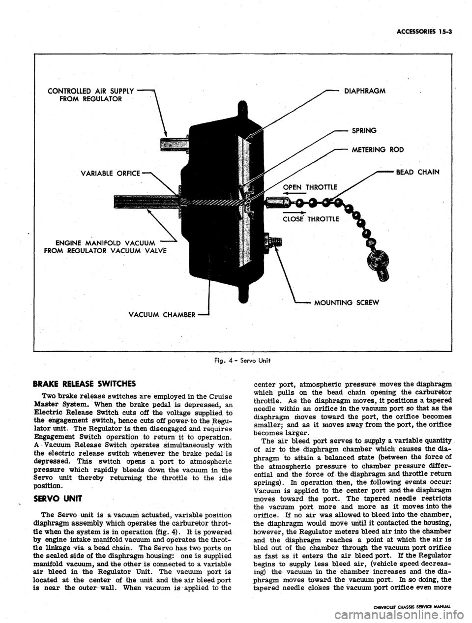
Fig.
4- Servo Unit
BRAKE RELEASE SWITCHES
Two brake release switches are employed in the Cruise
Master System. When the brake pedal is depressed, an
Electric Release Switch cuts off the voltage supplied to
the engagement switch, hence cuts off power to the Regu-
lator unit. The Regulator is then disengaged and requires
Engagement Switch operation to return it to operation.
A Vacuum Release Switch operates simultaneously with
the electric release switch whenever the brake pedal is
depressed. This switch opens a port to atmospheric
pressure which rapidly bleeds down the vacuum in the
Servo unit thereby returning the throttle to the idle
position.
SERVO UNIT
The Servo unit is a vacuum actuated, variable position
diaphragm assembly which operates the carburetor throt-
tle when the system is in operation (fig. 4). It is powered
by engine intake manifold vacuum and operates the throt-
tle linkage via a bead chain. The Servo has two ports on
the sealed side of the diaphragm housing: one is supplied
manifold vacuum, and the other is connected to a variable
air bleed in the Regulator Unit. The vacuum port is
located at the center of the unit and the air bleed port
is near the outer wall. When vacuum is applied to the
center port, atmospheric pressure moves the diaphragm
which pulls on the bead chain opening the carburetor
throttle. As the diaphragm moves, it positions a tapered
needle within an orifice in the vacuum port so that as the
diaphragm moves toward the port, the orifice becomes
smaller; and as it moves away from the port, the orifice
becomes larger.
The air bleed port serves to supply a variable quantity
of air to the diaphragm chamber which causes the dia-
phragm to attain a balanced state (between the force of
the atmospheric pressure to chamber pressure differ-
ential and the force of the diaphragm and throttle return
springs). In operation then, the following events occur:
Vacuum is applied to the center port and the diaphragm
moves toward the port. The tapered needle restricts
the vacuum port more and more as it moves into the
orifice. If no air was allowed to bleed into the chamber,
the diaphragm would move until it contacted the housing,
however, the Regulator meters bleed air into the chamber
and the diaphragm reaches a point at which the air is
bled out of the chamber through the vacuum port orifice
as fast as it enters the air bleed port. If the Regulator
begins to supply less bleed air, (vehicle speed decreas-
ing) the vacuum in the chamber increases and the dia-
phragm moves toward the vacuum port. In so doing, the
tapered needle closes the vacuum port orifice even more
CHEVROLET CHASSIS SERVICE MANUAL
Page 614 of 659
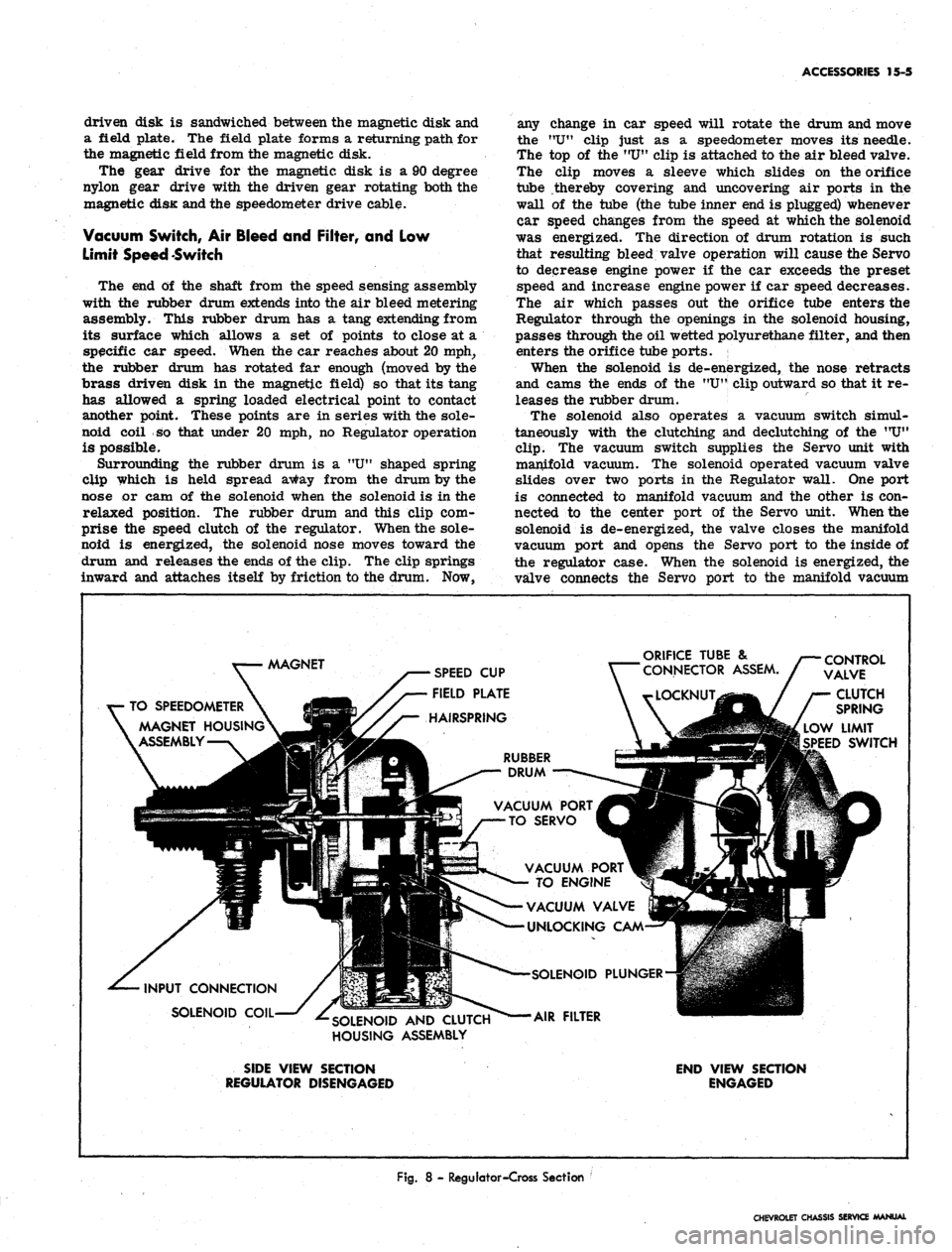
driven disk is sandwiched between the magnetic disk and
a field plate. The field plate forms a returning path for
the magnetic field from the magnetic disk.
The gear drive for the magnetic disk is a 90 degree
nylon gear drive with the driven gear rotating both the
magnetic disK and the speedometer drive cable.
Vacuum Switch, Air Bleed and Filter, and Low
Limit Speed Switch
The end of the shaft from the speed sensing assembly
with the rubber drum extends into the air bleed metering
assembly. This rubber drum has a tang extending from
its surface which allows a set of points to close at a
specific car speed. When the car reaches about 20 mph,
the rubber drum has rotated far enough (moved by the
brass driven disk in the magnetic field) so that its tang
has allowed a spring loaded electrical point to contact
another point. These points are in series with the sole-
noid coil so that under 20 mph, no Regulator operation
is possible.
Surrounding the rubber drum is a "U" shaped spring
clip which is held spread away from the drum by the
nose or cam of the solenoid when the solenoid is in the
relaxed position. The rubber drum and this clip com-
prise the speed clutch of the regulator. When the sole-
noid is energized, the solenoid nose moves toward the
drum and releases the ends of the clip. The clip springs
inward and attaches itself by friction to the drum. Now,
ACCESSORIES 15-5
any change in car speed will rotate the drum and move
the "U" clip just as a speedometer moves its needle.
The top of the MUtf clip is attached to the air bleed valve.
The clip moves a sleeve which slides on the orifice
tube thereby covering and uncovering air ports in the
wall of the tube (the tube inner end is plugged) whenever
car speed changes from the speed at which the solenoid
was energized. The direction of drum rotation is such
that resulting bleed valve operation will cause the Servo
to decrease engine power if the car exceeds the preset
speed and increase engine power if car speed decreases.
The air which passes out the orifice tube enters the
Regulator through the openings in the solenoid housing,
passes through the oil wetted polyurethane filter, and then
enters the orifice tube ports.
When the solenoid is de-energized, the nose retracts
and cams the ends of the "U" clip outward so that it re-
leases the rubber drum.
The solenoid also operates a vacuum switch simul-
taneously with the clutching and declutching of the "U"
clip.
The vacuum switch supplies the Servo unit with
manifold vacuum. The solenoid operated vacuum valve
slides over two ports in the Regulator wall. One port
is connected to manifold vacuum and the other is con-
nected to the center port of the Servo unit. When the
solenoid is de-energized, the valve closes the manifold
vacuum port and opens the Servo port to the inside of
the regulator case. When the solenoid is energized, the
valve connects the Servo port to the manifold vacuum
AAAGNET
SPEED CUP
FIELD PLATE
HAIRSPRING
TO SPEEDOMETER
MAGNET HOUSING
ASSEMBLY
ORIFICE TUBE &
CONNECTOR ASSEM.
CONTROL
VALVE
CLUTCH
SPRING
LOW LIMIT
SPEED SWITCH
RUBBER
DRUM
VACUUM PORT
TO SERVO
INPUT CONNECTION
SOLENOID COIL
SOLENOID AND CLUTCH
HOUSING ASSEMBLY
VACUUM PORT
TO ENGINE
VACUUM VALVE
UNLOCKING CAM
•SOLENOID PLUNGER
AIR FILTER
SIDE VIEW SECTION
REGULATOR DISENGAGED
END VIEW SECTION
ENGAGED
Fig.
8 - Regulator-Cross Section '
CHEVROLET CHASSIS SERVICE MANUAL
Page 615 of 659
ACCESSORIES
15-6
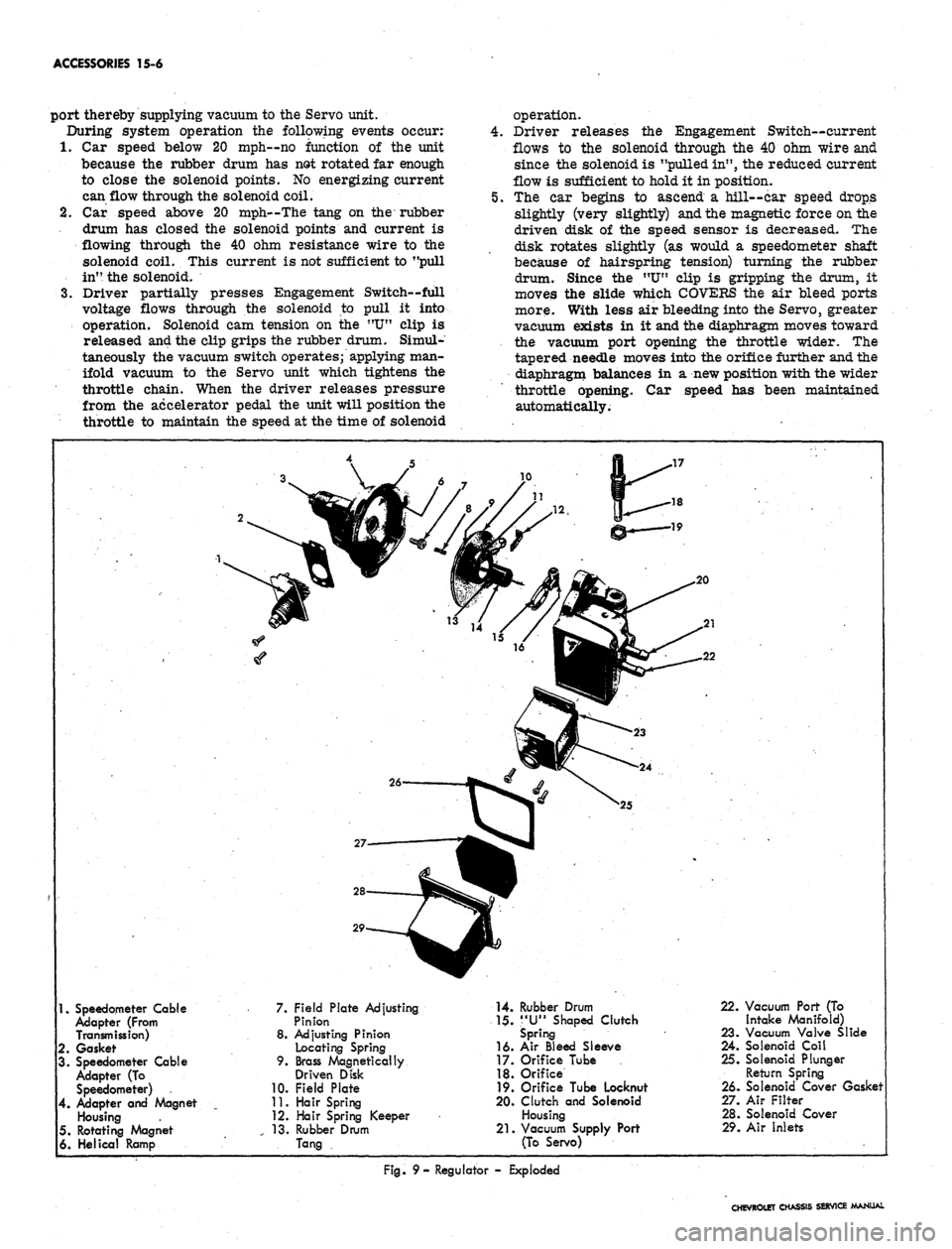
port thereby supplying vacuum to the Servo unit.
During system operation
the
following events occur:
1.
Car
speed below
20
mph—no function
of the
unit
because
the
rubber drum
has
not rotated
far
enough
to close
the
solenoid points.
No
energizing current
can flow through the solenoid coil.
2.
Car
speed above
20
mph—The tang
on the
rubber
drum
has
closed
the
solenoid points
and
current
is
flowing through
the 40 ohm
resistance wire
to the
solenoid coil. This current
is
not sufficient to "pull
in", the solenoid.
3.
Driver partially presses Engagement Switch—full
voltage flows through
the
solenoid
to
pull
it
into
operation. Solenoid
cam
tension
on the "U"
clip
is
released and the clip grips the rubber drum. Simul-
taneously the vacuum switch operates; applying man-
ifold vacuum
to the
Servo unit which tightens
the
throttle chain. When
the
driver releases pressure
from
the
accelerator pedal
the
unit will position the
throttle
to
maintain the speed
at
the time
of
solenoid
operation.
Driver releases
the
Engagement Switch—current
flows
to the
solenoid through
the 40
ohm wire and
since the solenoid is "pulled in", the reduced current
flow
is
sufficient to hold
it
in position.
The
car
begins
to
ascend
a
hill—car speed drops
slightly (very slightly) and the magnetic force on the
driven disk
of the
speed sensor
is
decreased.
The
disk rotates slightly
(as
would
a
speedometer shaft
because
of
hairspring tension) turning
the
rubber
drum. Since
the "U"
clip
is
gripping
the
drum,
it
moves
the
slide which COVERS
the air
bleed ports
more. With less air bleeding into the Servo, greater
vacuum exists
in it
and the diaphragm moves toward
the vacuum port opening
the
throttle wider.
The
tapered needle moves into the orifice further and the
diaphragm balances
in a
new position with the wider
throttle opening.
Car
speed
has
been maintained
automatically.
1.
Speedometer Cable
Adapter (From
Transmission)
2.
Gasket
3. Speedometer Cable
Adapter
(To
Speedometer)
4.
Adapter
and
Magnet
Housing
5. Rotating Magnet
6. Helical Ramp
7. Field Plate Adjusting
Pinion
8. Adjusting Pinion
Locating Spring
9. Brass Magnetically
Driven Disk
10.
Field Plate
11.
Hair Spring
12.
Hair Spring Keeper
13.
Rubber Drum
Tang
14.
Rubber Drum
1$.
"U"
Shaped Clutch
Spring
16.
Air
Bleed Sleeve
17.
Orifice Tube
18.
Orifice
19.
Orifice Tube Locknut
20.
Clutch
and
Solenoid
Housing
21.
Vacuum Supply Port
(To Servo)
22.
Vacuum Port (To
Intake Manifold)
23.
Vacuum Valve Slide
24.
Solenoid Coil
25.
Solenoid Plunger
Return Spring
26.
Solenoid Cover Gasket
27.
Air Filter
28.
Solenoid Cover
29.
Air Inlets
Fig.
9-
Regulator
-
Exploded
CHEVROLET CHASSIS SERVICE MANUAL