CHEVROLET CAMARO 1982 Repair Guide
Manufacturer: CHEVROLET, Model Year: 1982, Model line: CAMARO, Model: CHEVROLET CAMARO 1982Pages: 875, PDF Size: 88.64 MB
Page 141 of 875
GM – CAMARO 1982-1992 – Repair Guide (Checked by WxMax) 141
4. To isolate the short, probe a test point
at either end of the isolated circuit
(the light should be on or the mete r should indicate continuity).
5. Leave the test light probe engaged and sequentiall y open connectors or
switches, remove parts, etc. until t he light goes out or continuity is
broken.
6. When the light goes out, the shor t is between the last two circuit
components which were opened.
VOLTAGE
This test determines voltage available fr om the battery and should be the first
step in any electrical troubleshooting pr ocedure after visual inspection. Many
electrical problems, especially on co mputer controlled systems, can be caused
by a low state of charge in the battery. Excessive corrosion at the battery cable
terminals can cause poor contact that will prevent proper charging and f\
ull
battery current flow.
1. Set the voltmeter selector switch to the 20V position.
2. Connect the multimeter negative lead to the battery's negative (-) post or
terminal and the positive lead to t he battery's positive (+) post or
terminal.
3. Turn the ignition switch ON to provide a load.
4. A well charged battery should register over 12 volts. If the meter reads
below 11.5 volts, the battery power may be insufficient to operate the
electrical system properly.
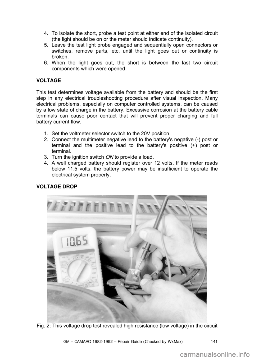
VOLTAGE DROP
Fig. 2: This voltage drop test revealed high resistance (low voltage) in the circuit
Page 142 of 875
GM – CAMARO 1982-1992 – Repair Guide (Checked by WxMax) 142
When current flows through
a load, the voltage beyond the load drops. This
voltage drop is due to the resistance created by the load and also by small
resistances created by corrosion at the connectors and damaged insulation on
the wires. The maximum allo wable voltage drop under load is critical, especially
if there is more than one load in t he circuit, since all voltage drops are
cumulative.
1. Set the voltmeter selector s witch to the 20 volt position.
2. Connect the multimeter negative lead to a good ground.
3. Operate the circuit a nd check the voltage prior to the first component
(load).
4. There should be little or no voltage drop in the circuit prior to the fi\
rst component. If a voltage drop exists, the wire or connectors in the circuit
are suspect.
5. While operating the first component in the circuit, probe the ground side
of the component with the positive meter lead and observe the voltage
readings. A small voltage drop should be noticed. This voltage drop is
caused by the resistance of the component.
6. Repeat the test for each component (load) down the circuit.
7. If a large voltage drop is noticed, the preceding component, wire or
connector is suspect.
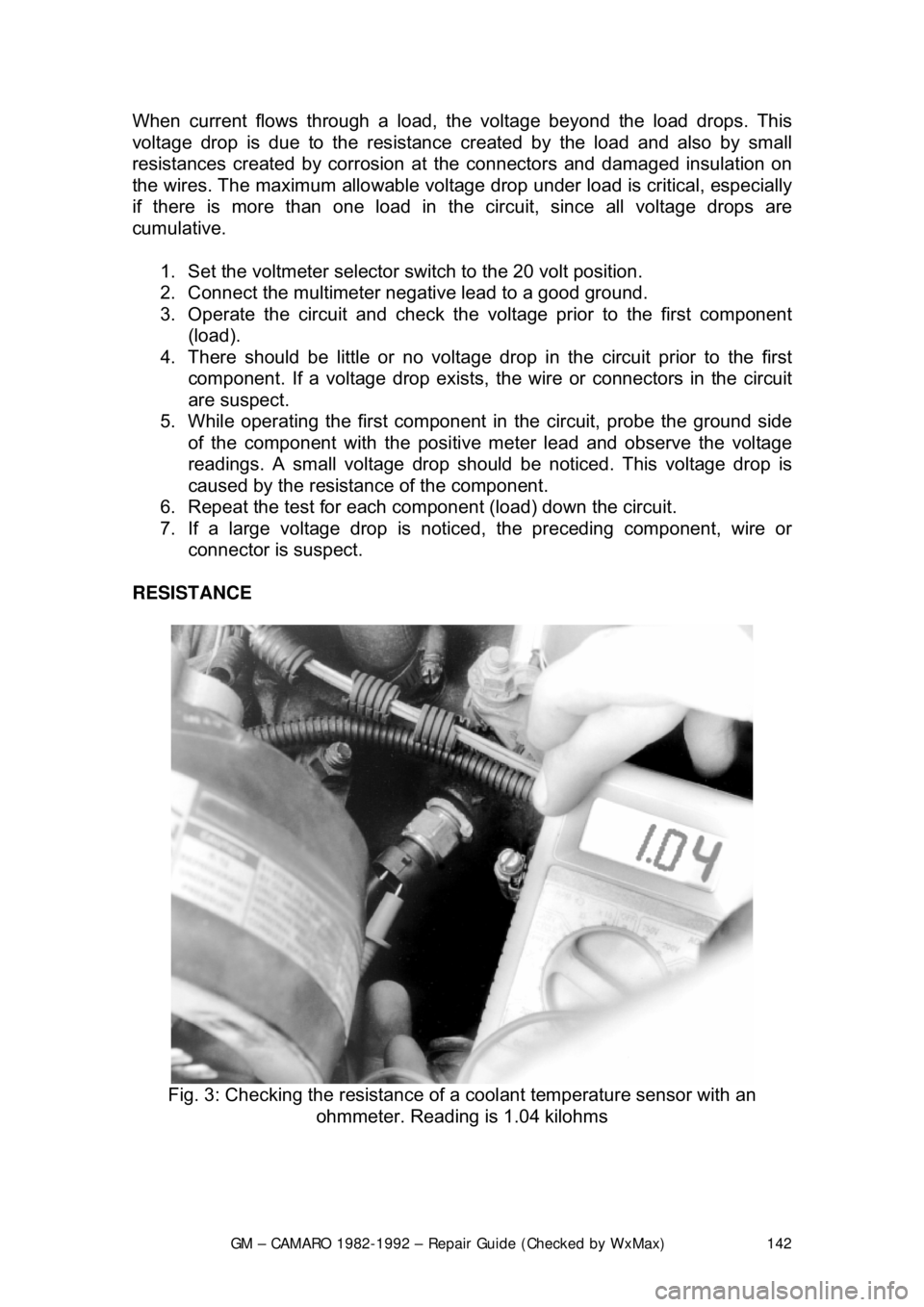
RESISTANCE
Fig. 3: Checking the resistance of a coolant temperature sensor with an
ohmmeter. Reading is 1.04 kilohms
Page 143 of 875
GM – CAMARO 1982-1992 – Repair Guide (Checked by WxMax) 143
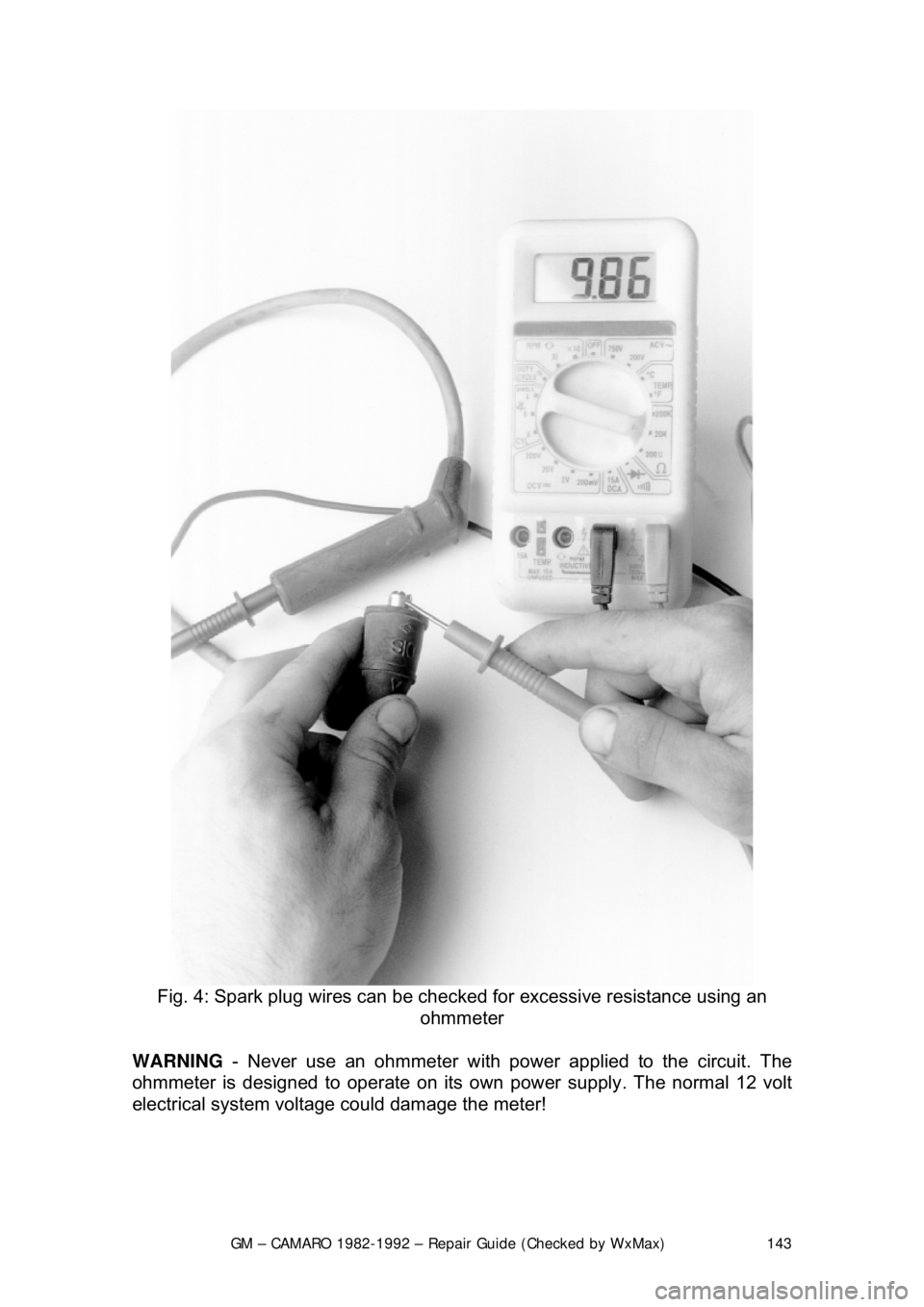
Fig. 4: Spark plug wires can be checked for excessive resistance using an
ohmmeter
WARNING - Never use an ohmmeter with power applied to the circuit. The
ohmmeter is designed to operate on its own power supply. The normal 12 volt
electrical system voltage could damage the meter!
Page 144 of 875

GM – CAMARO 1982-1992 – Repair Guide (Checked by WxMax) 144
1. Isolate the circuit from
the vehicle's power source.
2. Ensure that the ignition key is OFF when disconnecting any components
or the battery.
3. Where necessary, also isolate at least one side of the circuit to be
checked, in order to avoid reading parallel resistances. Parallel circuit
resistances will always give a lower reading than the actual resistance of
either of the branches.
4. Connect the meter leads to both sides of the circuit (wire or component)
and read the actual measured ohms on the meter scale. Make sure the
selector switch is set to the proper ohm scale for the circuit being tested,
to avoid misreading the oh mmeter test value.
WIRE AND CONNECTOR REPAIR
Almost anyone can replace damaged wires, as long as the proper tools and
parts are available. Wire and terminals ar e available to fit almost any need.
Even the specialized weatherproof, mol ded and hard shell connectors are now
available from aftermarket suppliers.
Be sure the ends of all the wires are fitted with t he proper terminal hardware
and connectors. Wrapping a wire around a stud is never a permanent solution
and will only cause trouble later. Repl ace wires one at a time to avoid
confusion. Always route wires exac tly the same as the factory.
If connector repair is necessary, only atte mpt it if you have the proper tools.
Weatherproof and hard shell con nectors require special tools to release the pins
inside the connector. Attempting to r epair these connectors with conventional
hand tools will damage them.
BATTERY CABLES
DISCONNECTING THE CABLES
When working on any electrical component on the vehicle, it is always a good
idea to disconnect the negative (-) battery cable. This will prevent potential
damage to many sensitive electrical co mponents such as the Engine Control
Module (ECM), radio, alternator, etc.
Any time you disengage the battery cables, it is recommended that you
disconnect the negative (&mdash) battery cable first. This will prevent your
accidentally grounding the positive (+) term inal to the body of the vehicle when
disconnecting it, thereby prevent ing damage to the above mentioned
components.
Before you disconnect the cable(s), first turn the ignition to the OFF position.
This will prevent a draw on the battery which could cause arcing (electricity
trying to ground itself to the body of a vehi cle, just like a spark plug jumping the
gap) and, of course, damaging some com ponents such as the alternator diodes.
Page 145 of 875

GM – CAMARO 1982-1992 – Repair Guide (Checked by WxMax) 145
When the battery cable(s) are reconnecte
d (negative cable last), be sure to
check that your lights, windshield wipers and other electrically operated safety
components are all working correctly. If your vehicle contains an Electronically
Tuned Radio (ETR), don't forget to also reset your radio stations. Ditto for the
clock.
Page 146 of 875
GM – CAMARO 1982-1992 – Repair Guide (Checked by WxMax) 146
SUPPLEMENTAL INFLATABLE RESTRAINT SYSTEM
GENERAL INFORMATION
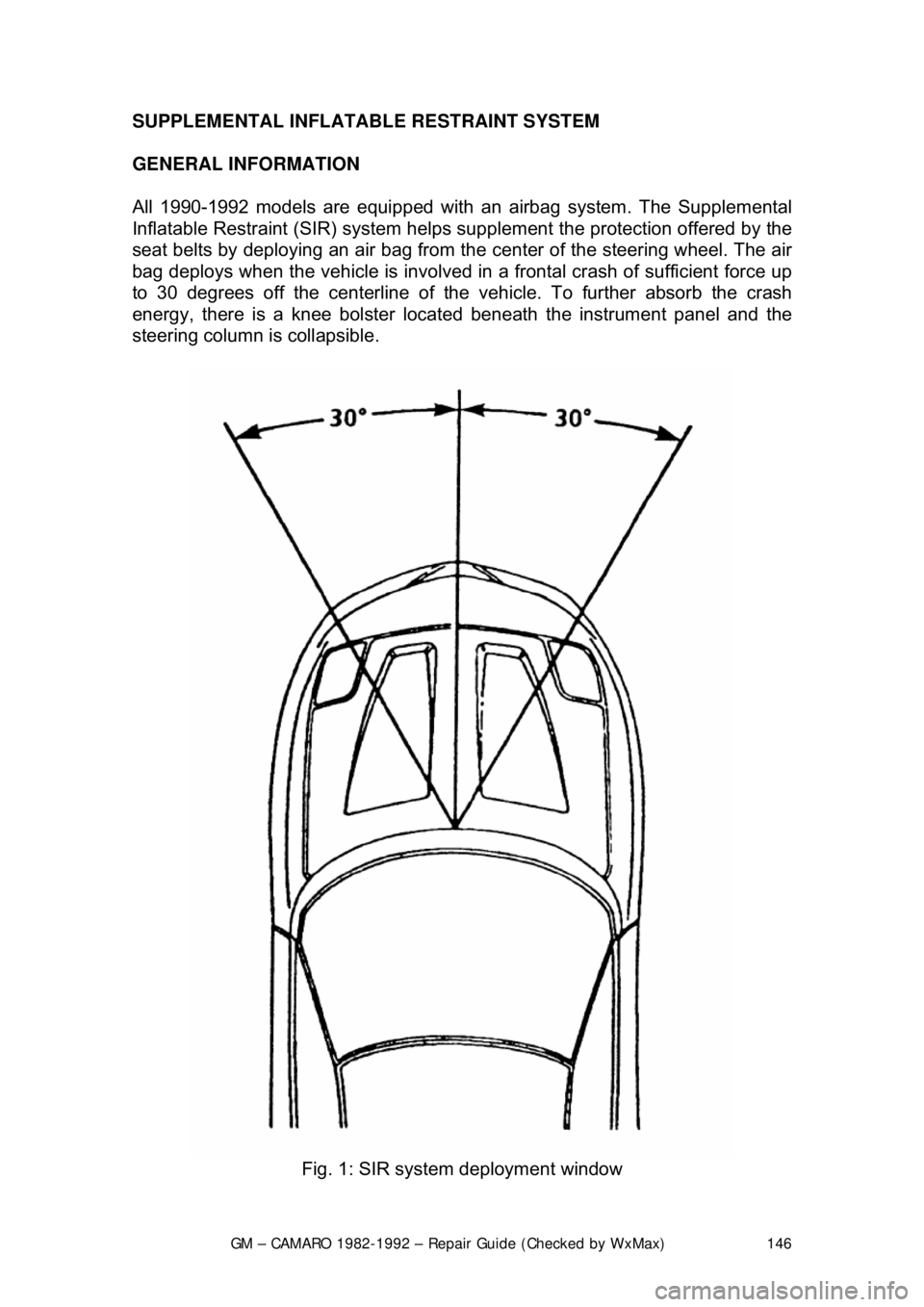
All 1990-1992 models are equi
pped with an airbag system. The Supplemental
Inflatable Restraint (SIR) syst em helps supplement the protection offered by the
seat belts by deploying an ai r bag from the center of the steering wheel. The air
bag deploys when the vehicle is involved in a frontal crash of sufficient force up
to 30 degrees off the center line of the vehicle. To further absorb the crash
energy, there is a knee bolster located beneath the instrument panel and the
steering column is collapsible.
Fig. 1: SIR system deployment window
Page 147 of 875

GM – CAMARO 1982-1992 – Repair Guide (Checked by WxMax) 147
SYSTEM OPERATION
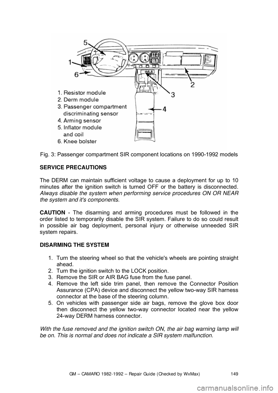
The main portions of the SIR system
are the deployment loops and the
Diagnostic Energy Reserve Module (D ERM). The main function of the
deployment loops is to supply current through the inflator module(s), which will
cause deployment of the air bag(s) in t he event of a frontal crash of sufficient
force. The arming sensor, SIR coil assembly (driver side only), passen\
ger
inflator module jumper (passenger side only), inflator module(s), passenger
compartment discriminating sensor and fo rward discriminating sensor make up
the deployment loops.
The DERM has two functions. One to supply the deployment loops with a 36
volt reserve to ensure sufficient energy is available to deploy the airbag(s) if the
battery voltage feed to the arming sensor is lost during a frontal crash. Another
function is SIR electrical system diagnostics.
The arming sensor switches power to th e inflator module(s) on the high side
(power side) of the deployment loops. Ei ther of the discriminating sensors can
supply ground to the inflator module(s) on the low side (ground side) of the loop.
The inflator module(s) ar e only supplied sufficient cu rrent to deploy when the
arming sensor and at least one of the two discriminating sensors are closed
simultaneously.
SYSTEM COMPONENTS
DIAGNOSTIC ENERGY RESERVE MODULE
The DERM is designed to perform the following functions in the SIR system:
• Energy Reserve - Maintains 36 volt energy reserve(s) to provide
deployment energy when the vehicle volt age is low or lost in a frontal
impact
• Malfunction Detection - Performs diagnostic monitoring of the SIR
system electrical components
• Malfunction Recording - Provides diagnostic trouble code information
• Frontal Crash Recording - Record s the SIR system status during a
frontal crash
WARNING LAMP
The "INFL REST" or "AIR BAG" warning lamp is used to do the following:
• Verify lamp and DERM oper ation by flashing seven to nine times when
the ignition key is first turned ON
• Warn the driver of SIR electrical system faults which could potentially
affect the operation of the SIR system
• Provide diagnostic information by fl ashing the fault codes when the
diagnostic mode is enabled
Page 148 of 875
GM – CAMARO 1982-1992 – Repair Guide (Checked by WxMax) 148
ARMING SENSOR
The arming sensor is a protective switch
located in the power feed side of the
deployment loop. It is calibrated to clos e at low level velocity changes (lower
than the discriminating sens ors). This assures that the inflator module is
connected directly to the 36 volt output of the DERM or battery voltage feed
when either of the discrim inating sensors close.
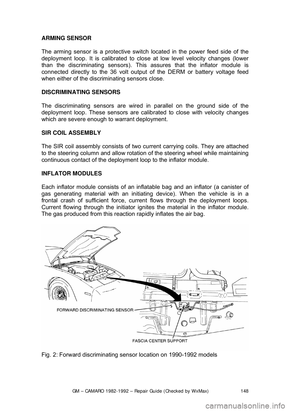
DISCRIMINATING SENSORS
The discriminating sensors are wired in parallel on the ground side of the
deployment loop. These sensors are calib rated to close with velocity changes
which are severe enough to warrant deployment.
SIR COIL ASSEMBLY
The SIR coil assembly consists of two cu rrent carrying coils. They are attached
to the steering column and allow rotation of the steering wheel while maintaining
continuous contact of the deployment loop to the inflator module.
INFLATOR MODULES
Each inflator module consists of an inflat able bag and an inflator (a canister of
gas generating material with an initiati ng device). When the vehicle is in a
frontal crash of sufficient force, current flows through the deployment loops.
Current flowing through the initiator ignite s the material in the inflator module.
The gas produced from this reaction rapidly inflates the air bag.
Fig. 2: Forward discriminating se nsor location on 1990-1992 models
Page 149 of 875
GM – CAMARO 1982-1992 – Repair Guide (Checked by WxMax) 149
Fig. 3: Passenger com partment SIR component lo cations on 1990-1992 models
SERVICE PRECAUTIONS
The DERM can maintain sufficient volt age to cause a deployment for up to 10
minutes after the ignition switch is tur ned OFF or the battery is disconnected.
Always disable the system when perfo rming service procedures ON OR NEAR
the system and it's components.
CAUTION - The disarming and arming procedures must be followed in the
order listed to temporarily disable the SI R system. Failure to do so could result
in possible air bag deployment, pers onal injury or otherwise unneeded SIR
system repairs.
DISARMING THE SYSTEM
1. Turn the steering wheel so that t he vehicle's wheels are pointing straight
ahead.
2. Turn the ignition switch to the LOCK position.
3. Remove the SIR or AIR BAG fuse from the fuse panel.
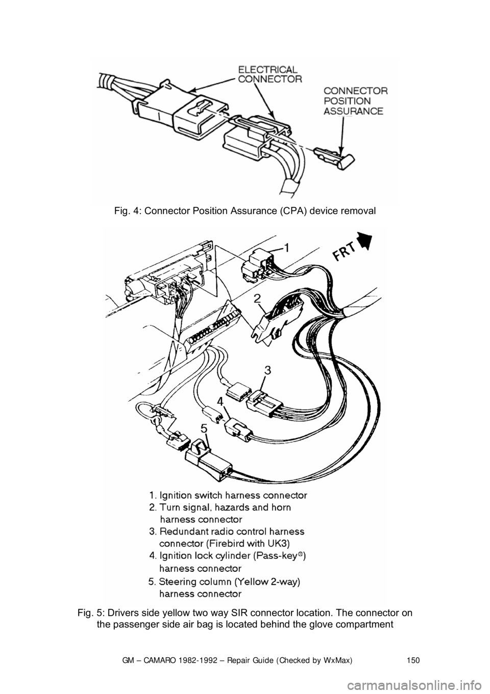
4. Remove the left side trim panel, t hen remove the Connector Position
Assurance (CPA) device and disconnec t the yellow two-way SIR harness
connector at the base of the steering column.
5. On vehicles with passenger side air bags, remove the glove box door
then disconnect the yellow two-way c onnector located near the yellow
24-way DERM harness connector.
With the fuse removed and the ignition sw itch ON, the air bag warning lamp will
be on. This is normal and does not indicate a SIR system malfunction.
Page 150 of 875
GM – CAMARO 1982-1992 – Repair Guide (Checked by WxMax) 150
Fig. 4: Connector Position Assurance (CPA) device removal
Fig. 5: Drivers side yellow two way SIR connector location. The connecto\
r on
the passenger side air bag is loca ted behind the glove compartment