CHEVROLET CAMARO 1982 Repair Guide
Manufacturer: CHEVROLET, Model Year: 1982, Model line: CAMARO, Model: CHEVROLET CAMARO 1982Pages: 875, PDF Size: 88.64 MB
Page 121 of 875

GM – CAMARO 1982-1992 – Repair Guide (Checked by WxMax) 121
air! Avoid inhaling any dust from any
brake surface! When cleaning brake
surfaces, use a commercially available brake cleaning fluid.
1. Raise the car and support it with jackstands.
2. Loosen the adjusting nut at the equalizer.
3. Disengage the rear cabl e at the connector.
4. Remove the wheel assembly and brake drum.
5. Bend the retainer fingers.
6. Disengage the cable at the brake shoe operating lever.
To install:
7. Engage the cable at the brake shoe operating lever.
8. Bend the retainer fingers.
9. Install the wheel a ssembly and brake drum.
10. Engage the rear cabl e at the connector.
11. Adjust the parking brake by t he adjusting nut at the equalizer.
12. Lower the car.
DISC BRAKES
1. Raise the car and support it with jackstands.
2. Loosen the adjusting nut at the equalizer.
3. Disengage the cable at the connector.
4. Push forward on the caliper parking brak e apply lever. This allows the cable
to be removed from the tang. Then, release the lever.
5. Pull on the caliper parki ng brake apply lever to engage the cable to the tang.
6. Engage the cable at the connector.
7. Adjust the parking brake cable by the adjusting nut at the equalizer.
8. Apply the parking brake 3 times with heavy pressure and repeat adjustment.
9. Lower the car.
ADJUSTMENT
The parking brake cable is adjustable only on 1982-89 vehicles. All 1990-92
vehicles feature a self- adjusting parking brake.
REAR DRUM BRAKES
1. Depress the parking brake leve r exactly two ratchet clicks.
2. Raise the rear of the vehicl e and support safely with jackstands.
3. Tighten the brake cable adjusting nut until the left rear wheel can be turned
rearward with both hands, but locks when forward rotation is attempted. \
4. Release the parking brake le ver; both rear wheels must turn freely in either
direction without brake drag.
5. Lower the vehicle.
Page 122 of 875

GM – CAMARO 1982-1992 – Repair Guide (Checked by WxMax) 122
REAR DISC BRAKES
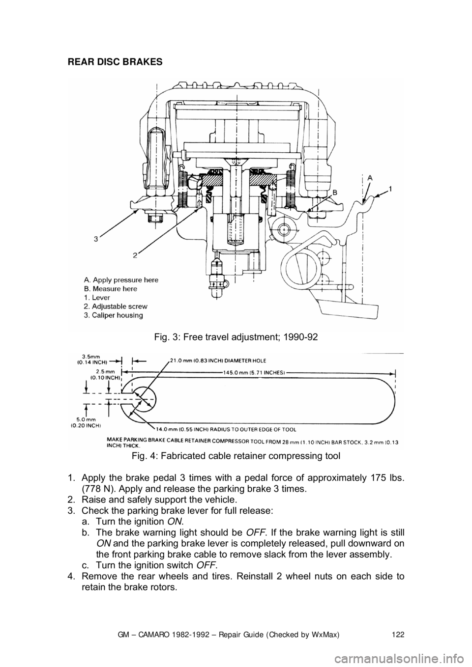
Fig. 3: Free trav el adjustment; 1990-92
Fig. 4: Fabricated cable retainer compressing tool
1. Apply the brake pedal 3 times with a pedal force of approximately 175 lbs.
(778 N). Apply and release t he parking brake 3 times.
2. Raise and safely support the vehicle.
3. Check the parking brake lever for full release: a. Turn the ignition ON.
b. The brake warning light should be OFF. If the brake warning light is still
ON and the parking brake lever is comple tely released, pull downward on
the front parking brake cable to remove slack from the lever assembly.
c. Turn the ignition switch OFF.
4. Remove the rear wheels and tires. Reinstall 2 wheel nuts on each side to
retain the brake rotors.
Page 123 of 875

GM – CAMARO 1982-1992 – Repair Guide (Checked by WxMax) 123
5. Pull the parking lever 4 clicks. T
he parking brake levers on both calipers
should be against the lever stops on the caliper housings. If the levers are
not against the stops, check for binding in the rear cables and/or loosen the
cables at the equalizer nut until both left and right levers are against their
stops.
6. Adjust the equalizer adjusting nut unt il the parking brake levers on both
calipers just begin to mo ve off their stops.
7. Back off the adjuster nut until the le vers move back, barely touching their
stops.
8. Operate the parking brak e lever several times to check adjustment. After
cable adjustment, the parking brake le ver should travel no more than 14
ratchet clicks. The rear wheels shoul d not turn forward when the parking
brake lever is applied 8-16 ratchet clicks.
9. Release the parking brake lever. Both rear whee ls must turn freely in both
directions. The parking brake levers on both calipers should be resting on
their stops.
10. Remove the wheel nuts retaining t he rotors. Install the wheel and tire
assemblies.
11. Lower the vehicle.
PARKING BRAKE FREE-TRAVEL
ADJUSTMENT
1989-92 MODELS
REAR DISC BRAKES
Disc brake pads must be new or parallel to within 0.006 in. (0.15mm). Parking
brake adjustment is not valid wit h heavily tapered pads and may cause
caliper/parking brake binding. Replace tapered brak e pads. Parking brake free-
travel should only be made if the caliper has been taken apart. This adjustment
will not correct a condition where the caliper levers will not return to their stops.
1. Have an assistant apply a light brake pedal load, enough to stop the rotor
from turning by hand. This takes up all clearances and ensures that
components are correctly aligned.
2. Apply light pressure to the caliper lever.
3. Measure the free-travel between t he caliper lever and the caliper housing.
The free-travel must be 0.0024-0.028 in. (0.6-0.7mm).
4. If the free-travel is incorrect, do the following: a. Remove the adjuster screw.
b. Clean the thread adhesive re sidue from the threads.
c. Coat the threads with adhesive.
d. Screw in the adjuster screw far enough to obtain 0.024-0.028 in. (0.6-
0.7mm) free-travel between the caliper lever and the caliper housing.
5. Have an assistant release the brak e pedal, then apply the brake pedal firmly
3 times. Recheck the free-travel and adjust as necessary.
Page 124 of 875

GM – CAMARO 1982-1992 – Repair Guide (Checked by WxMax) 124
BRAKE LEVER
REMOVAL & INSTALLATION
1982-89 MODELS
1. Raise and safely support the vehicle.
2. Remove the adjusting nut
at the equalizer and remove the front cable from
the equalizer and bracket.
3. Lower the vehicle.
4. Remove the upper console and lower c onsole rear screws. Lift the rear of
the lower console to gain access to the parking brake control.
5. Remove the pin and retainer from t he control assembly and front cable.
6. Remove the cable and casing from the control assembly and bracket then
remove the cable and grommet from the vehicle. Remove the parking brake
lever mounting bolts and remove the assembly.
7. Installation is the reverse of t he removal procedure. Adjust the parking
brake.
1990-92 MODELS
1. Remove the carpet finish molding.
2. Remove the console assembly.
3. With the parking brake lever in the do wn position, rotate the arm toward the
front of the vehicle until a 3mm metal pen can be inserted into the hole.
Insert the metal pin into the hole, locking out the self adjuster.
4. Raise and safely support the vehicle.
5. Disconnect the rear cables from the equalizer.
6. Lower the vehicle.
7. Remove the barrel-shaped butt on from the adjuster track.
8. Remove the parking brake lever mounting bolts.
9. Remove the front cable and casing from the control assembly using a
fabricated parking brake cable retainer compressor tool.
10. Installation is the reverse of the removal procedure. Cycle the lever to set
the parking lever and cables in there proper location.
Page 125 of 875

GM – CAMARO 1982-1992 – Repair Guide (Checked by WxMax) 125
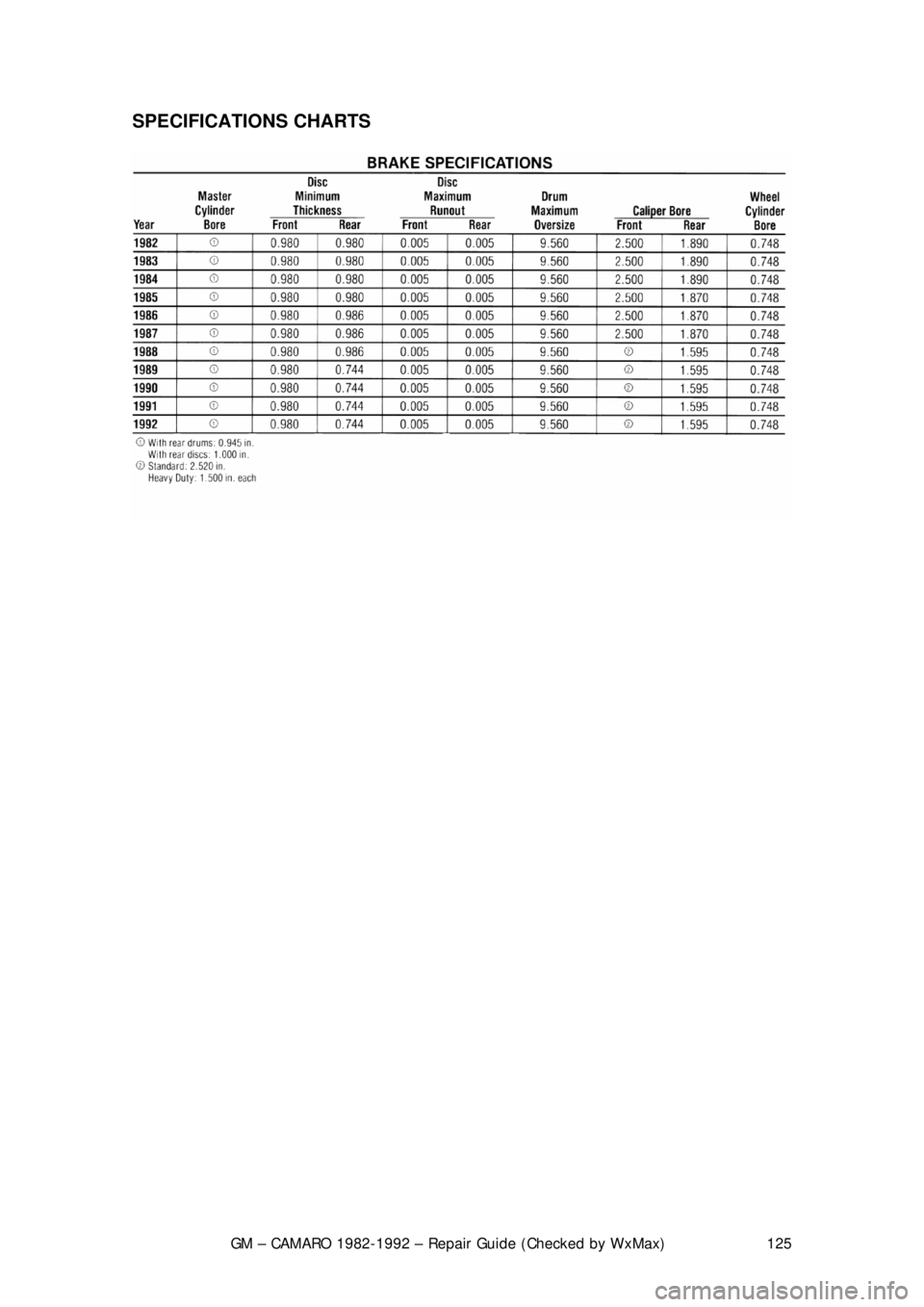
SPECIFICATIONS CHARTS
Page 126 of 875

GM – CAMARO 1982-1992 – Repair Guide (Checked by WxMax) 126
CHASSIS ELECTRICAL
UNDERSTANDING AND TROUBLESHOOTING ELECTRICAL SYSTEMS
BASIC ELECTRICAL THEORY
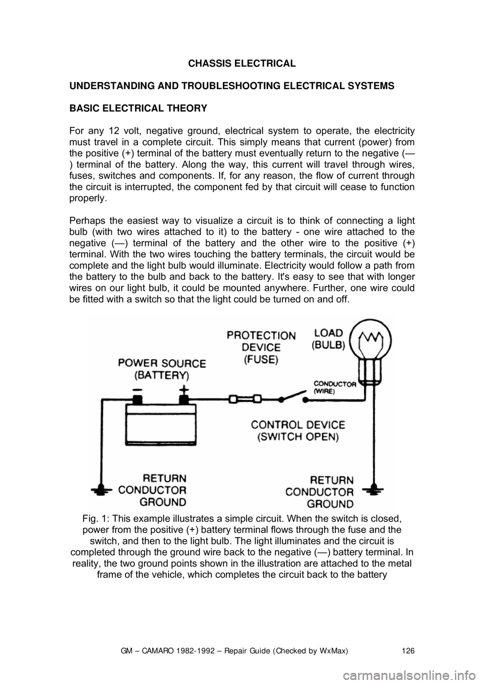
For any 12 volt, negative ground, electrical system to operate, the electricity
must travel in a complete circuit. This simply means that current (power) from
the positive (+) terminal of the battery must eventually return to the negative (—
) terminal of the battery. Along the way, this current will travel through wires,
fuses, switches and components. If, for any reason, the flow of current through
the circuit is interrupted, the component f ed by that circuit will cease to function
properly.
Perhaps the easiest way to visualize a circ uit is to think of connecting a light
bulb (with two wires attac hed to it) to the battery - one wire attached to the
negative (—) terminal of the battery and the other wire to the positive (+)
terminal. With the two wires touching the battery terminals, the circuit would be
complete and the light bulb would illuminat e. Electricity would follow a path from
the battery to the bulb and back to the bat tery. It's easy to see that with longer
wires on our light bulb, it could be mounted anywhere. Further, one wire could
be fitted with a switch so that t he light could be turned on and off.
Fig. 1: This example illu strates a simple circuit. Wh en the switch is closed,
power from the positive (+) battery te rminal flows through the fuse and the
switch, and then to the light bulb. The light illuminates and the circuit is
completed through the ground wire back to the negative (—) battery terminal. In
reality, the two ground point s shown in the illustration are attached to the metal
frame of the vehicle, which comple tes the circuit back to the battery
Page 127 of 875

GM – CAMARO 1982-1992 – Repair Guide (Checked by WxMax) 127
The normal automotive circuit differs from
this simple example in two ways.
First, instead of having a return wire from the bulb to the battery, the current
travels through the frame of the vehicle. Since the negative (—) battery cable is
attached to the frame (made of electrically conductive metal), the frame of the
vehicle can serve as a ground wire to complete the circuit. Secondly, mo\
st
automotive circuits contain multiple components which receive power from a
single circuit. This lessens the amount of wire needed to power components on
the vehicle.
HOW DOES ELECTRICITY WORK: THE WATER ANALOGY
Electricity is the flow of electrons - t he subatomic particles that constitute the
outer shell of an atom. Elec trons spin in an orbit around the center core of an
atom. The center core is comprised of protons (positive charge) and neutrons
(neutral charge). Electrons have a negativ e charge and balance out the positive
charge of the protons. When an outside forc e causes the number of electrons to
unbalance the charge of the protons, the electrons will split off the atom and
look for another atom to balance out. If th is imbalance is kept up, electrons will
continue to move and an elec trical flow will exist.
Many people have been taught electrical th eory using an analogy with water. In
a comparison with water flowing through a pipe, the electrons would be the
water and the wire is the pipe.
The flow of electricity can be measur ed much like the flow of water through a
pipe. The unit of measur ement used is amperes, frequently abbreviated as
amps (a). You can compare amperage to th e volume of water flowing through a
pipe. When connected to a circuit, an ammeter will measure the actual amount
of current flowing through the circuit. W hen relatively few electrons flow through
a circuit, the amperage is low. When many electrons flow, the amperage is high.
Water pressure is measured in units su ch as pounds per square inch (psi); The
electrical pressure is m easured in units called volts (v). When a voltmeter is
connected to a circuit, it is meas uring the electrical pressure.
The actual flow of electricity depends not only on voltage and amperage, but
also on the resistance of the circuit. T he higher the resistance, the higher the
force necessary to push the current through the circuit. The standard unit for
measuring resistance is an ohm. Resistance in a circuit varies depending on the
amount and type of components used in t he circuit. The main factors which
determine resistance are:
• Material - some materials have more resistance than others. Those with
high resistance are said to be insulato rs. Rubber materials (or rubber-like
plastics) are some of the most common insulators used in vehicles as
they have a very high resistance to electricity. Very low resistance
materials are said to be conductors. Copper wire is among the best
conductors. Silver is actually a super ior conductor to copper and is used
in some relay contacts, but its hi gh cost prohibits its use as common
wiring. Most automotive wir ing is made of copper.
Page 128 of 875

GM – CAMARO 1982-1992 – Repair Guide (Checked by WxMax) 128
•
Size - the larger the wire size being used, the less resistance the wire will
have. This is why components which use large amounts of electricity
usually have large wires suppl ying current to them.
• Length - for a given thickness of wire, the longer the wire, the greater the
resistance. The shorter the wire, the less the resistance. When
determining the proper wire for a circ uit, both size and length must be
considered to design a circuit that can handle the current needs of the
component.
• Temperature - with many materials, the higher the temperature, the
greater the resistance (positive temper ature coefficient). Some materials
exhibit the opposite trait of lower re sistance with higher temperatures
(negative temperature coefficient). Thes e principles are used in many of
the sensors on the engine.
OHM'S LAW
There is a direct relationship between current, voltage and resistance. The
relationship between current, voltage and resistance can be summed up by a
statement known as Ohm's law.
Voltage (E) is equal to amper age (I) times resistance (R): E=I x ROther forms of
the formula are R=E/I and I=E/R
In each of these formulas, E is the voltage in volts, I is the current in amps and
R is the resistance in ohms. The basic point to remember is that as the
resistance of a circuit goes up, the amount of current that flows in the circuit will
go down, if voltage remains the same.
The amount of work that the electricity can perform is expressed as power. The
unit of power is the watt (w). The re lationship between power, voltage and
current is expressed as:
Power (w) is equal to amperage (I) times voltage (E): W=I x EThis is only true
for direct current (DC) circuits; The alte rnating current formula is a tad different,
but since the electrical circuits in mo st vehicles are DC type, we need not get
into AC circuit theory.
ELECTRICAL COMPONENTS
POWER SOURCE
Power is supplied to the vehicle by tw o devices: The battery and the alternator.
The battery supplies electrical power dur ing starting or during periods when the
current demand of the vehicle's electrical system exceeds the output capacity of
the alternator. The alternator supplies electrical current when the engine is
running. Just not does the al ternator supply the current needs of the vehicle, but
it recharges the battery.
Page 129 of 875

GM – CAMARO 1982-1992 – Repair Guide (Checked by WxMax) 129
THE BATTERY
In most modern vehicles, the battery is
a lead/acid electrochemical device
consisting of six 2 volt subs ections (cells) connected in se ries, so that the unit is
capable of producing approximately 12 volt s of electrical pressure. Each
subsection consists of a series of positive and negative plates held a short
distance apart in a solution of sulfuric acid and water.
The two types of plates are of dissim ilar metals. This sets up a chemical
reaction, and it is this r eaction which produces current flow from the battery
when its positive and negative terminals are connected to an electrical \
load .
The power removed from the battery is r eplaced by the alternator, restoring the
battery to its original chemical state.
THE ALTERNATOR
On some vehicles there isn't an alter nator, but a generator. The difference is
that an alternator supplies alternating current which is then changed to direct
current for use on the vehicle, while a generator produces direct current.
Alternators tend to be more efficient and that is why they are used.
Alternators and generators are devices t hat consist of coils of wires wound
together making big electrom agnets. One group of coils spins within another set
and the interaction of the magnetic fields causes a current to flow. This current
is then drawn off the coils and fed into the vehicles electrical system.
GROUND
Two types of grounds are used in automot ive electric circuits. Direct ground
components are grounded to the frame thr ough their mounting points. All other
components use some sort of ground wire which is attached to the frame or
chassis of the vehicle. The electrical current runs through the chassis of the
vehicle and returns to the battery thr ough the ground (—) cable; if you look,
you'll see that the battery ground cabl e connects between the battery and the
frame or chassis of the vehicle.
It should be noted that a good percentage of electrical problems can be traced
to bad grounds.
PROTECTIVE DEVICES
It is possible for large surges of current to pass through the electrical system of
your vehicle. If this surge of current we re to reach the load in the circuit, the
surge could burn it out or severely dam age it. It can also overload the wiring,
causing the harness to get hot and melt t he insulation. To prevent this, fuses,
circuit breakers and/or fusible links are connected into the supply wires of the
electrical system. These items are nothing more than a built-in weak spot in the
system. When an abnormal amount of curr ent flows through the system, these
protective devices work as fo llows to protect the circuit:
Page 130 of 875

GM – CAMARO 1982-1992 – Repair Guide (Checked by WxMax) 130
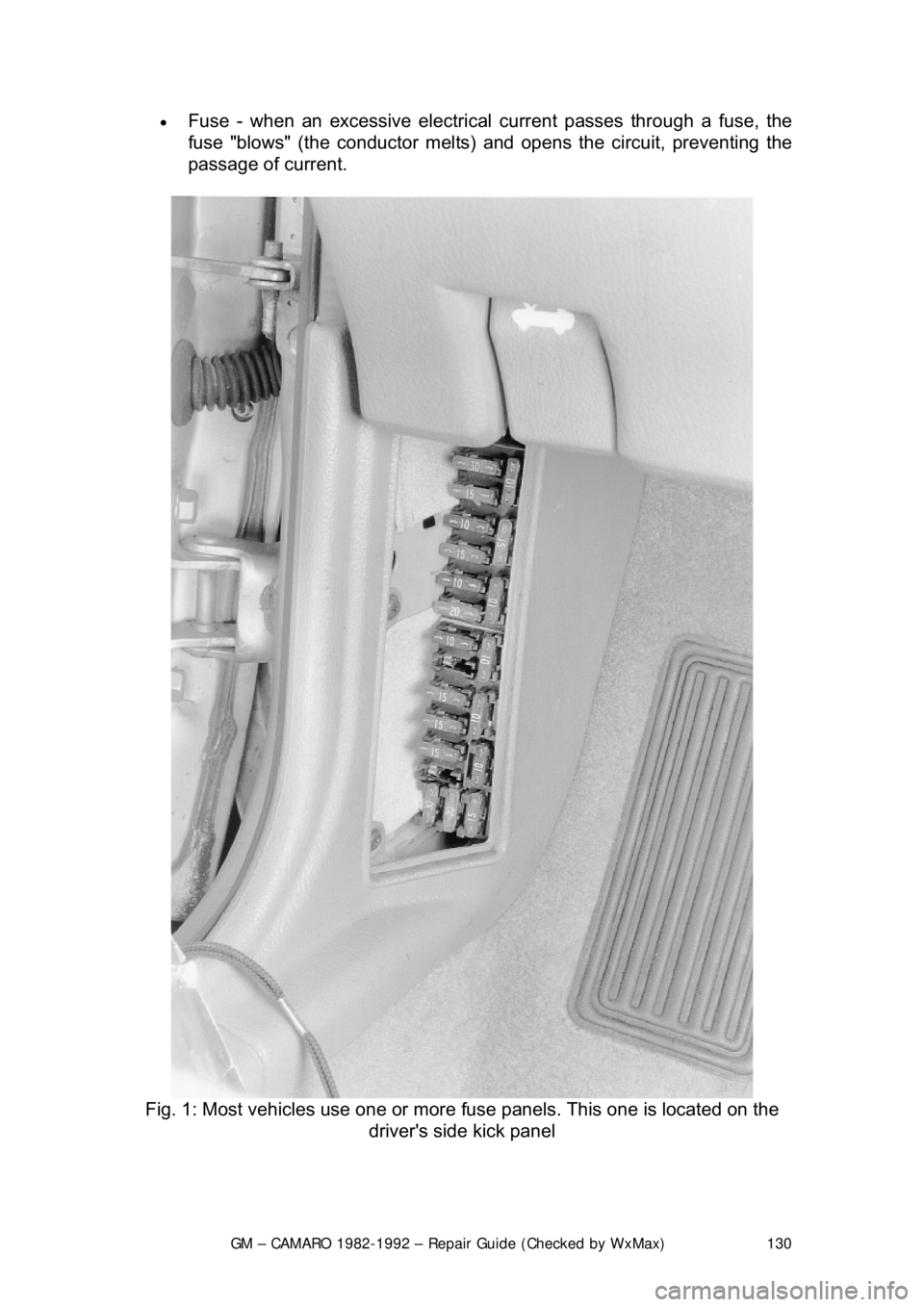
•
Fuse - when an excessive electrical current passes through a fuse, the
fuse "blows" (the conductor melts) and opens the circuit, preventing the
passage of current.
Fig. 1: Most vehicles use one or more fuse panels. This one is located on the
driver's side kick panel