CHEVROLET CAMARO 1982 Repair Guide
Manufacturer: CHEVROLET, Model Year: 1982, Model line: CAMARO, Model: CHEVROLET CAMARO 1982Pages: 875, PDF Size: 88.64 MB
Page 131 of 875
GM – CAMARO 1982-1992 – Repair Guide (Checked by WxMax) 131
•
Circuit Breaker - a circuit breaker is basically a self-repairing fuse. It will
open the circuit in the same fashio n as a fuse, but when the surge
subsides, the circuit breaker can be reset and does not need
replacement.
• Fusible Link - a fusible link (fuse link or main link) is a short length of
special, high temperatur e insulated wire that acts as a fuse. When an
excessive electrical current passes th rough a fusible link, the thin gauge
wire inside the link melt s, creating an intentional open to protect the
circuit. To repair the circuit, the link must be replaced. Some newer type
fusible links are housed in plug-in modules, which are simply replaced
like a fuse, while older type fusible lin ks must be cut and spliced if they
melt. Since this link is very early in the electrical path, it's the first place to
look if nothing on the vehicle works, yet the battery seems to be charged
and is properly connected.
CAUTION - Always replace fuses, circ uit breakers and fusible links with
identically rated component s. Under no circumstances should a component of
higher or lower amperage rating be substituted.
SWITCHES & RELAYS
Switches are used in electrical circuits to control the passage of current. The
most common use is to open and close circuits between the battery and the
various electric devices in the system. Switches are rated according to the
amount of amperage they c an handle. If a sufficient amperage rated switch is
not used in a circuit, the switch could overload and cause damage.
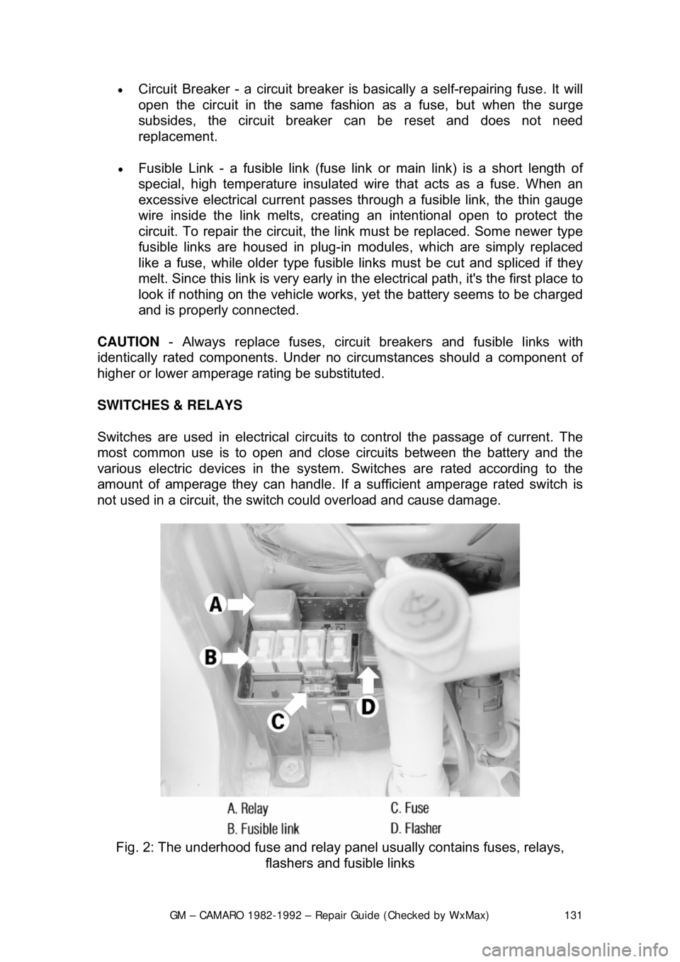
Fig. 2: The underhood fuse and relay panel usually contains fuses, relays,
flashers and fusible links
Page 132 of 875
GM – CAMARO 1982-1992 – Repair Guide (Checked by WxMax) 132
Some electrical components which require
a large amount of current to operate
use a special switch called a relay. Sinc e these circuits carry a large amount of
current, the thickness of the wire in the ci rcuit is also greater. If this large wire
were connected from the load to the c ontrol switch, the switch would have to
carry the high amperage load and the fair ing or dash would be twice as large to
accommodate the increased size of t he wiring harness. To prevent these
problems, a relay is used.
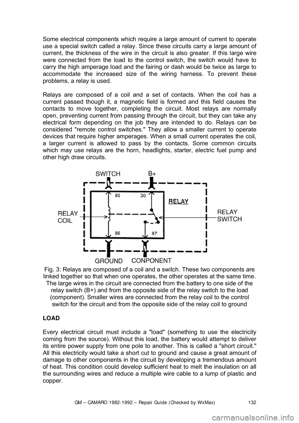
Relays are composed of a coil and a se t of contacts. When the coil has a
current passed though it, a magnetic fiel d is formed and this field causes the
contacts to move together, completing the circuit. Most relays are normally
open, preventing current from passing thr ough the circuit, but they can take any
electrical form depending on th e job they are intended to do. Relays can be
considered "remote control switches." They allow a smaller current to operate
devices that require higher amperages. W hen a small current operates the coil,
a larger current is allo wed to pass by the contacts. Some common circuits
which may use relays are the horn, headlight s, starter, electric fuel pump and
other high draw circuits.
Fig. 3: Relays are composed of a coil and a switch. These two components are
linked together so that w hen one operates, the other operat es at the same time.
The large wires in the circuit are connect ed from the battery to one side of the
relay switch (B+) and from the opposite side of the re lay switch to the load
(component). Smaller wires are connected from the relay coil to the control
switch for the circuit and from the opposite side of the relay coil to ground
LOAD
Every electrical circuit must include a "load" (something to use the electricity
coming from the source). Without this l oad, the battery would attempt to deliver
its entire power supply from one pole to another. This is called a "short circuit."
All this electricity would take a short cut to ground and cause a great amount of
damage to other components in the circui t by developing a tremendous amount
of heat. This condition could develop suffici ent heat to melt the insulation on all
the surrounding wires and reduce a multiple wire cable to a lump of plastic and
copper.
Page 133 of 875

GM – CAMARO 1982-1992 – Repair Guide (Checked by WxMax) 133
WIRING & HARNESSES
The average vehicle contains meters
and meters of wiring, with hundreds of
individual connections. To protect the many wires from damage and to keep
them from becoming a confusing tangl e, they are organized into bundles,
enclosed in plastic or taped together and called wiring harnesses. Different
harnesses serve different parts of the vehi cle. Individual wires are color coded
to help trace them through a harness wher e sections are hidden from view.
Automotive wiring or circuit conductors can be either single strand wire, multi-
strand wire or printed circui try. Single strand wire has a solid metal core and is
usually used inside such components as alternators, motors, relays and other
devices. Multi-strand wire has a core made of many small strands of wire
twisted together into a single conductor. Most of the wiring in an automotive
electrical system is made up of multi-strand wire, either as a single conductor or
grouped together in a harness. All wiring is color coded on the insulator, either
as a solid color or as a colored wire wit h an identification stripe. A printed circuit
is a thin film of copper or other conducto r that is printed on an insulator backing.
Occasionally, a printed circuit is sandwic hed between two sheets of plastic for
more protection and flexibility. A comp lete printed circuit, consisting of
conductors, insulating material and connec tors for lamps or other components
is called a printed circuit board. Printed ci rcuitry is used in place of individual
wires or harnesses in places where space is limit ed, such as behind instrument
panels.
Since automotive electrical systems are very sensitive to changes in resistance,
the selection of properly sized wires is critical when systems are repaired. A
loose or corroded connection or a replacem ent wire that is too small for the
circuit will add extra resistance and an addi tional voltage drop to the circuit.
The wire gauge number is an expression of the cross-section area of the
conductor. Vehicles from countries that use the metric system will typically
describe the wire size as its cross-secti onal area in square millimeters. In this
method, the larger the wire, the gr eater the number. Another common system
for expressing wire size is the Americ an Wire Gauge (AWG) system. As gauge
number increases, area decreases and the wire becomes smaller. An 18 gauge
wire is smaller than a 4 gauge wire. A wire with a higher gauge number will
carry less current than a wire with a lower gauge number. Gauge wire size
refers to the size of the strands of the conductor, not the size of the complete
wire with insulator. It is possi ble, therefore, to have two wires of the same gauge
with different diameters because one may hav e thicker insulation than the other.
It is essential to understand how a circuit works before trying to figure out why it
doesn't. An electrical schematic shows the electrical current paths when a
circuit is operating proper ly. Schematics break the enti re electrical system down
into individual circuits. In a schematic, usually no attempt is made to represent
wiring and components as they physically appear on the vehicle; switches and
other components are shown as simply as possible. Face views of harness
connectors show the cavity or terminal lo cations in all multi-pin connectors to
help locate test points.
Page 134 of 875
GM – CAMARO 1982-1992 – Repair Guide (Checked by WxMax) 134
CONNECTORS
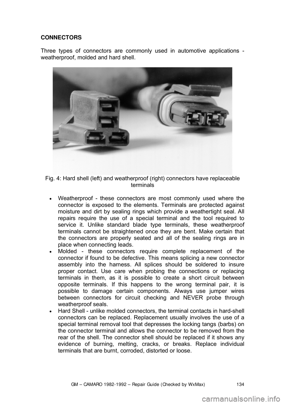
Three types of connectors
are commonly used in automotive applications -
weatherproof, molded and hard shell.
Fig. 4: Hard shell (left) and weather proof (right) connectors have replaceable
terminals
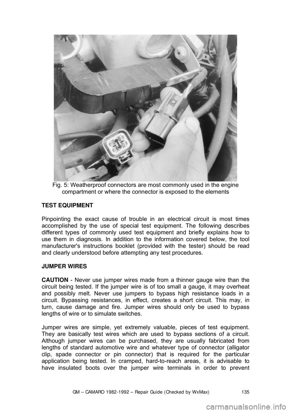
• Weatherproof - these connectors ar e most commonly used where the
connector is exposed to the element s. Terminals are protected against
moisture and dirt by sealing rings wh ich provide a weathertight seal. All
repairs require the use of a specia l terminal and the tool required to
service it. Unlike standard blade ty pe terminals, these weatherproof
terminals cannot be straightened once they are bent. Make certain that
the connectors are properly seated and all of the sealing rings are in
place when connecting leads.
• Molded - these connectors require complete replacement of the
connector if found to be defective. This means splicing a new connector
assembly into the harness. All sp lices should be soldered to insure
proper contact. Use care when probi ng the connections or replacing
terminals in them, as it is possibl e to create a short circuit between
opposite terminals. If this happens to the wrong terminal pair, it is
possible to damage certain com ponents. Always use jumper wires
between connectors for circuit c hecking and NEVER probe through
weatherproof seals.
• Hard Shell - unlike molded connectors, the terminal contacts in hard-shell
connectors can be replaced. Replacement usually involves the use of a
special terminal removal tool that depresses the locking tangs (barbs)\
on
the connector terminal and allows the connector to be removed from the
rear of the shell. The connector she ll should be replaced if it shows any
evidence of burning, melting, cracks, or breaks. Replace individual
terminals that are burnt, corroded, distorted or loose.
Page 135 of 875
GM – CAMARO 1982-1992 – Repair Guide (Checked by WxMax) 135
Fig. 5: Weatherproof connectors ar e most commonly used in the engine
compartment or where the connecto r is exposed to the elements
TEST EQUIPMENT
Pinpointing the exact cause of trouble in an electrical circuit is most times
accomplished by the use of special te st equipment. The following describes
different types of commonly used test eq uipment and briefly explains how to
use them in diagnosis. In addition to t he information covered below, the tool
manufacturer's instructions booklet (pro vided with the tester) should be read
and clearly understood before atte mpting any test procedures.
JUMPER WIRES
CAUTION - Never use jumper wires made from a thinner gauge wire than the
circuit being tested. If the jumper wire is of too small a gauge, it may overheat
and possibly melt. Never use jumpers to bypass high resistance loads in a
circuit. Bypassing resistances, in effect, cr eates a short circuit. This may, in
turn, cause damage and fire. Jumper wi res should only be used to bypass
lengths of wire or to simulate switches.
Jumper wires are simple, yet extremel y valuable, pieces of test equipment.
They are basically test wir es which are used to bypass sections of a circuit.
Although jumper wires can be purchased, they are usually fabricated from
lengths of standard automot ive wire and whatever type of connector (alligator
clip, spade connector or pin connector) that is required for the particular
application being tested. In cramped, hard- to-reach areas, it is advisable to
have insulated boots over the jumper wire terminals in order to prevent
Page 136 of 875
GM – CAMARO 1982-1992 – Repair Guide (Checked by WxMax) 136
accidental grounding. It is al
so advisable to include a standard automotive fuse
in any jumper wire. This is commonly referred to as a "fused jumper". By
inserting an in-line fuse holder between a set of test leads, a fused jumper wire
can be used for bypassing open circuits. Use a 5 amp fuse to provide protection
against voltage spikes.
Jumper wires are used primarily to locate open electrical circuits, on either the
ground (—) side of the circuit or on the power (+) side. If an electrical
component fails to operate, connect t he jumper wire between the component
and a good ground. If the component operates only with the jumper installed,
the ground circuit is open. If the ground circuit is good, but the component does
not operate, the circuit between the power feed and component may be open.
By moving the jumper wire successively back from the component toward the
power source, you can isolate the area of the circuit where the open is located.
When the component stops func tioning, or the power is cut off, the open is in
the segment of wire between the jumper and the point previously tested.
You can sometimes connect the jumper wir e directly from the battery to the
"hot" terminal of the component, but firs t make sure the component uses 12
volts in operation. Some electrical components, such as fuel injectors or
sensors, are designed to operate on about 4 to 5 volts, and running 12 volts
directly to these components will cause damage.
TEST LIGHTS
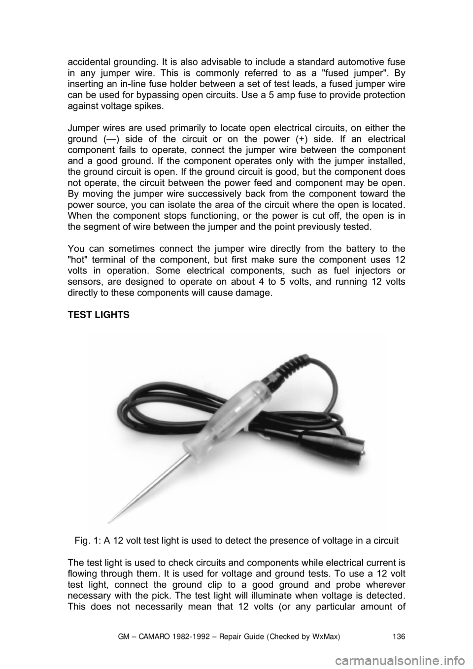
Fig. 1: A 12 volt test light is used to detect the presence of voltage in a circuit
The test light is used to check circuits and components while electrical current is
flowing through them. It is used for volt age and ground tests. To use a 12 volt
test light, connect the ground clip to a good ground and probe wherever
necessary with the pick. The test light will illuminate when voltage is detected.
This does not necessarily mean that 12 volts (or any particular amount of
Page 137 of 875

GM – CAMARO 1982-1992 – Repair Guide (Checked by WxMax) 137
voltage) is present; it only means that so
me voltage is present. It is advisable
before using the test light to touch its ground clip and probe across the battery
posts or terminals to make sure the light is operating properly.
WARNING - Do not use a test light to probe electronic ignition, spark plug or
coil wires. Never use a pick-type test light to probe wiring on computer
controlled systems unless spec ifically instructed to do so. Any wire insulation
that is pierced by the test light pr obe should be taped and sealed with silicone
after testing
Like the jumper wire, the 12 volt test li ght is used to isolate opens in circuits.
But, whereas the jumper wire is used to bypass the open to operate the load,
the 12 volt test light is us ed to locate the presence of voltage in a circuit. If the
test light illuminates, there is power up to t hat point in the circuit; if the test light
does not illuminate, there is an open circui t (no power). Move the test light in
successive steps back toward the power source until the light in the handle
illuminates. The open is between the pr obe and a point which was previously
probed.
The self-powered test light is similar in design to the 12 volt test light, but
contains a 1.5 volt penlight battery in the handle. It is most often used in place
of a multimeter to check for open or shor t circuits when power is isolated from
the circuit (continuity test).
The battery in a self-powered test light does not provide much current. A weak
battery may not provide enough power to illuminate the test light even when a
complete circuit is made (especially if there is high resistance in the circuit).
Always make sure that the test battery is strong. To check the battery, briefly
touch the ground clip to the pr obe; if the light glows brightly, the battery is strong
enough for testing.
A self-powered test light should not be used on any co mputer controlled system
or component. The small amount of electr icity transmitted by the test light is
enough to damage many electr onic automotive components.
MULTIMETERS
Multimeters are an extremely useful tool for troubleshooting electrical problems.
They can be purchased in either analog or digital form and have a price range
to suit any budget. A multimeter is a voltmeter, ammeter and ohmmeter (along
with other features) combined into one instrument. It is often used when testing
solid state circuits because of its hi gh input impedance (usually 10 megaohms
or more). A brief description of the mult imeter main test functions follows:
• Voltmeter - the voltmeter is used to measure voltage at any point in a
circuit, or to measure the voltage drop across any part of a circuit.
Voltmeters usually have various scales and a selector switch to allow the
reading of different volt age ranges. The voltmeter has a positive and a
negative lead. To avoid damage to the meter, always connect the
negative lead to the negative (—) side of the circ uit (to ground or nearest
Page 138 of 875

GM – CAMARO 1982-1992 – Repair Guide (Checked by WxMax) 138
the ground side of the circuit) and
connect the positive lead to the
positive (+) side of the circuit (to t he power source or the nearest power
source). Note that the negative voltme ter lead will always be black and
that the positive voltmeter will alwa ys be some color other than black
(usually red).
• Ohmmeter - the ohmmeter is designed to read resistance (measured in
ohms) in a circuit or component. Mo st ohmmeters will have a selector
switch which permits the measurement of different ranges of resistance
(usually the selector swit ch allows the multiplication of the meter reading
by 10, 100, 1,000 and 10,000). Some ohmmeters are "auto-ranging"
which means the meter itself will dete rmine which scale to use. Since the
meters are powered by an internal battery, the ohmmeter can be used
like a self-powered test light. When the ohmmeter is connected, current
from the ohmmeter flows through the ci rcuit or component being tested.
Since the ohmmeter's internal resi stance and voltage are known values,
the amount of current flow throug h the meter depends on the resistance
of the circuit or component being test ed. The ohmmeter can also be used
to perform a continuity test for suspected open circuits. In using the
meter for making continuity checks, do not be concerned with the actual
resistance readings. Zero resistance, or any ohm reading, indicates
continuity in the circui t. Infinite resistance indi cates an opening in the
circuit. A high resistance reading w here there should be none indicates a
problem in the circuit. Checks for s hort circuits are made in the same
manner as checks for open circuits, ex cept that the circuit must be
isolated from both power and normal gr ound. Infinite resistance indicates
no continuity, while zero resi stance indicates a dead short.
WARNING - Never use an ohmmeter to check the resistance of a component or
wire while there is volt age applied to the circuit
• Ammeter - an ammeter measures the am ount of current flowing through
a circuit in units called amperes or amps. At normal operating voltage,
most circuits have a characteristic amount of amperes, called "current
draw" which can be measured usi ng an ammeter. By referring to a
specified current draw rating, then measuring the amperes and
comparing the two values, one can det ermine what is happening within
the circuit to aid in diagnosis. An open circuit, for example, will not allow
any current to flow, so the amme ter reading will be zero. A damaged
component or circuit will have an incr eased current draw, so the reading
will be high. The ammeter is always connected in series with the circuit\
being tested. All of the current that normally flows through the circuit
must also flow through the ammeter; if there is any other path for the
current to follow, the ammeter readi ng will not be accurate. The ammeter
itself has very little resistance to curr ent flow and, therefore, will not affect
the circuit, but it will measure current draw only when the circuit is closed
and electricity is flowing. Excessive current draw can blow fuses and
drain the battery, while a reduced current draw can cause motors to run \
slowly, lights to dim and other components to not operate properly.
Page 139 of 875

GM – CAMARO 1982-1992 – Repair Guide (Checked by WxMax) 139
TROUBLESHOOTING ELECTRICAL SYSTEMS
When diagnosing a specific problem, or
ganized troubleshooting is a must. The
complexity of a modern automotive v ehicle demands that you approach any
problem in a logical, organized m anner. There are certain troubleshooting
techniques, however, which are standard:
• Establish when the problem occurs. D oes the problem appear only under
certain conditions? Were there any noises, odors or other unusual
symptoms? Isolate the problem area. To do this, make some simple tests
and observations, then eliminate the syst ems that are working properly.
Check for obvious problems, such as broken wires and loose or dirty
connections. Always check the obvious before assuming something
complicated is the cause.
• Test for problems systematically to determine the cause once the
problem area is isolated. Are all t he components functioning properly? Is
there power going to electrical switc hes and motors. Performing careful,
systematic checks will often turn up mo st causes on the first inspection,
without wasting time checking co mponents that have little or no
relationship to the problem.
• Test all repairs after the work is done to make sure that the problem is
fixed. Some causes can be traced to more than one component, so a
careful verification of repair work is important in order to pick up
additional malfunctions that may cause a problem to reappear or a
different problem to arise. A blown fu se, for example, is a simple problem
that may require more than another fuse to repair. If you don't look for a
problem that caused a fuse to blow, a shorted wire (for example) may go
undetected.
Experience has shown that most problem s tend to be the result of a fairly
simple and obvious cause, such as loose or corroded connectors, bad grounds
or damaged wire insulation which causes a short. This makes careful visual
inspection of components during testing essential to quick and accurate
troubleshooting.
Page 140 of 875
GM – CAMARO 1982-1992 – Repair Guide (Checked by WxMax) 140
TESTING
OPEN CIRCUITS
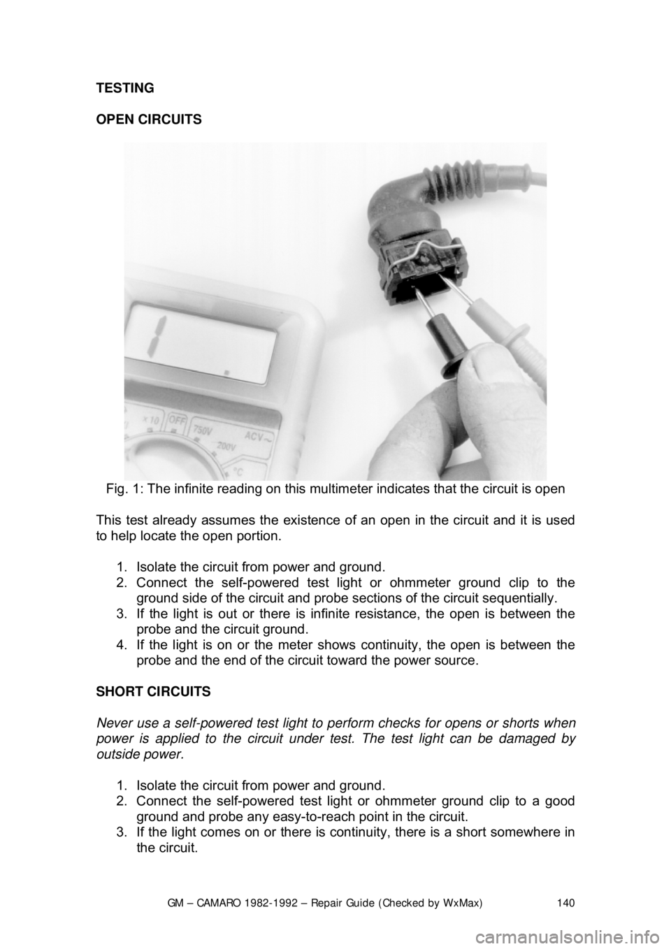
Fig. 1: The infinite reading on this mult imeter indicates that the circuit is open
This test already assumes the existence of an open in the circuit and it is used
to help locate the open portion.
1. Isolate the circuit from power and ground.
2. Connect the self-powered test light or ohmmeter ground clip to the
ground side of the circuit and probe sect ions of the circuit sequentially.
3. If the light is out or there is infinite resistanc e, the open is between the
probe and the circuit ground.
4. If the light is on or the meter s hows continuity, the open is between the
probe and the end of the circuit toward the power source.
SHORT CIRCUITS
Never use a self-powered test light to per form checks for opens or shorts when
power is applied to the circuit under te st. The test light can be damaged by
outside power.
1. Isolate the circuit from power and ground.
2. Connect the self-powered test light or ohmmeter ground clip to a good
ground and probe any easy-to-reach point in the circuit.
3. If the light comes on or there is cont inuity, there is a short somewhere in
the circuit.