CHEVROLET CAMARO 1982 Repair Guide
Manufacturer: CHEVROLET, Model Year: 1982, Model line: CAMARO, Model: CHEVROLET CAMARO 1982Pages: 875, PDF Size: 88.64 MB
Page 161 of 875
GM – CAMARO 1982-1992 – Repair Guide (Checked by WxMax) 161
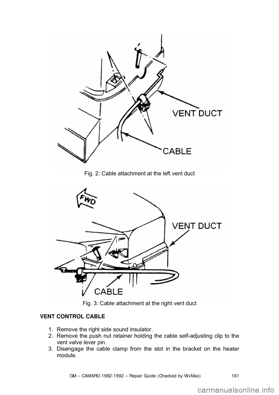
Fig. 2: Cable attachment at the left vent duct
Fig. 3: Cable attachment at the right vent duct
VENT CONTROL CABLE 1. Remove the right side sound insulator.
2. Remove the push nut retainer holdi ng the cable self-adjusting clip to the
vent valve lever pin.
3. Disengage the cable clam p from the slot in the bracket on the heater
module.
Page 162 of 875

GM – CAMARO 1982-1992 – Repair Guide (Checked by WxMax) 162
4. Remove the radio and heater
control panel trim plate.
5. Remove the heater control head attaching screws and remove the control head.
6. Pull the vent control cable clip from the control assembly, then tilt the
assembly to slip the vent control cable end loop off the pin of the mode
lever.
7. Remove the vent control cable.
To install: 8. Install the vent control cable to the control assembly and install the
control head.
9. Install the radio and heat er control trim plate.
10. Fit the cable self-adjusting clip onto the vent valve lever pin.
11. Snap the cable clamp into the slot in the bracket on the heater module.
12. Install the push nut retainer to the vent valve lever pin.
13. Install the right side sound insulator.
14. Check operation and adjust the cable if necessary.
DEFROST CONTROL CABLE 1. Remove the left side sound insulator.
2. Remove the push nut retainer holdi ng the cable self-adjusting clip to the
defroster valve lever pin at the heater module.
3. Disengage the cable clam p from the slot in the bracket on the heater
module.
4. Remove the radio and heat er control trim plate.
5. Remove the control head assembly.
6. Disconnect the defroster control cabl e by pulling the cable clip from the
control assembly. Then tilt the contro l assembly to slip the control cable
end loop off the pin of the mode lever.
7. Remove the cable.
To install: 8. Install the defroster c ontrol cable to the contro l assembly and install the
control head.
9. Install the radio and heat er control trim plate.
10. Fit the cable self-adjusting clip onto the defroster valve lever pin.
11. Snap the cable clamp into the slot in the bracket on the heater module.
12. Install the push nut retainer to the defroster valve lever pin.
13. Install the left side sound insulator.
14. Check operation and adjust the cable if necessary.
Page 163 of 875
GM – CAMARO 1982-1992 – Repair Guide (Checked by WxMax) 163
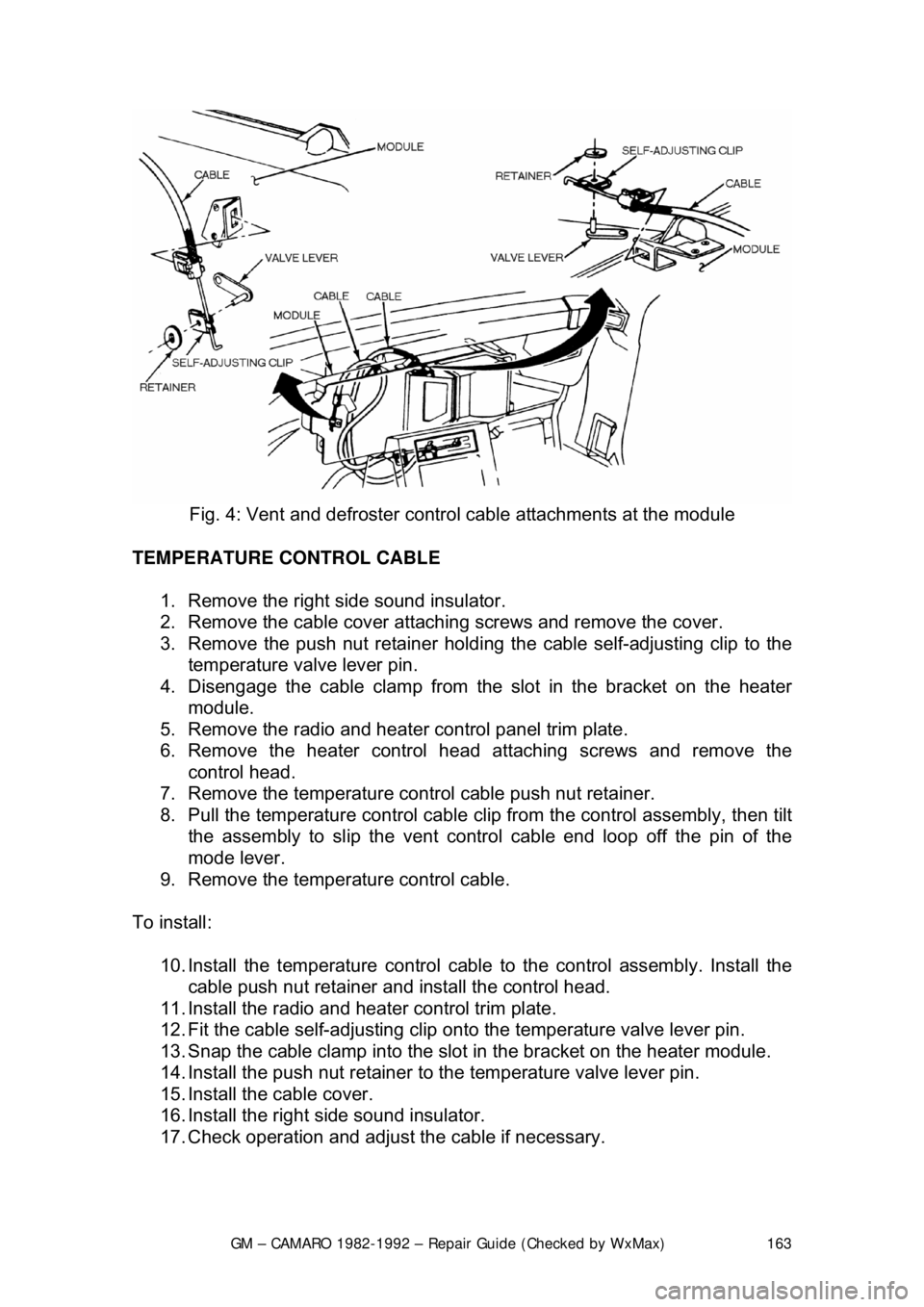
Fig. 4: Vent and defroster contro l cable attachments at the module
TEMPERATURE CONTROL CABLE 1. Remove the right side sound insulator.
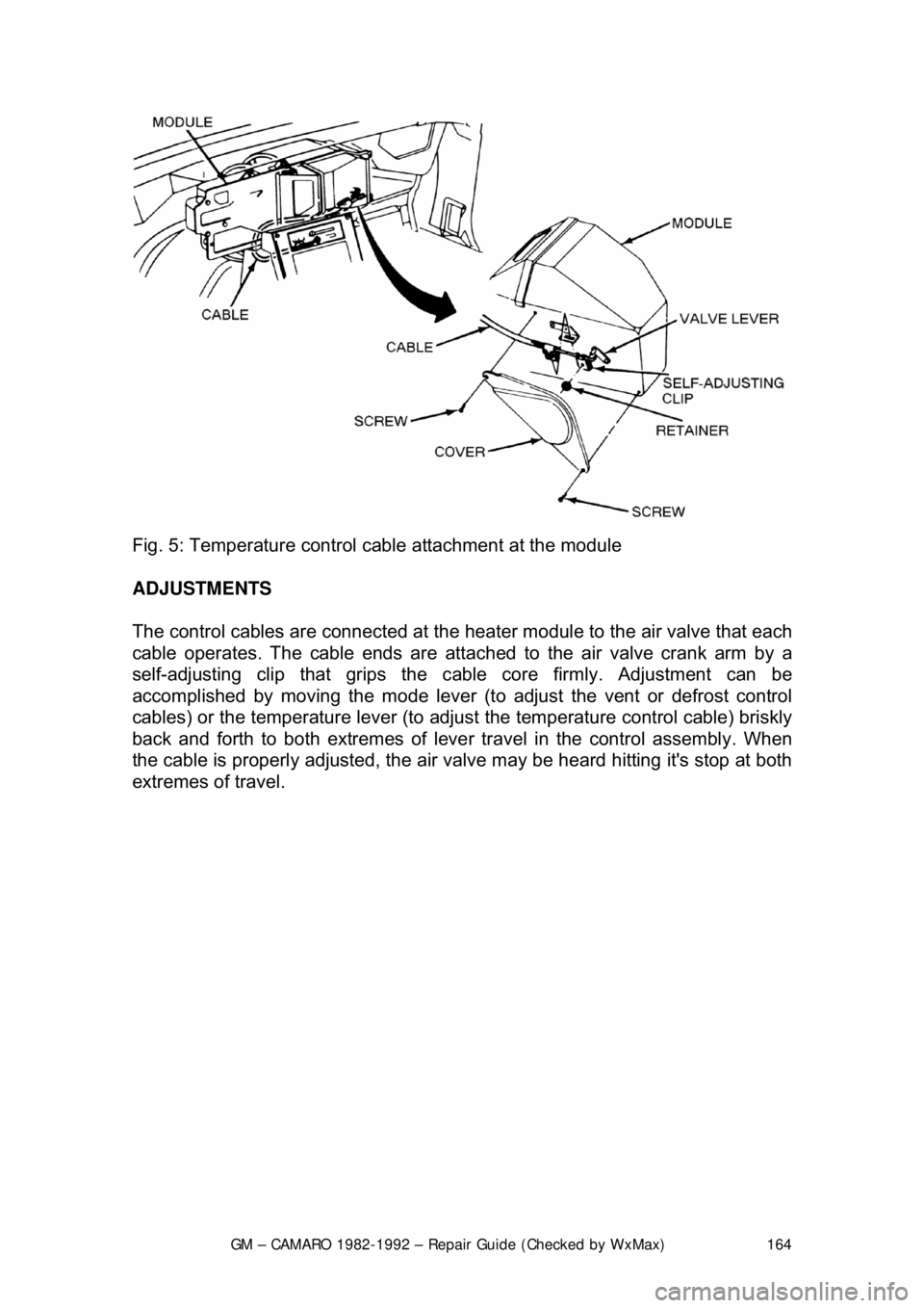
2. Remove the cable cover attach ing screws and remove the cover.
3. Remove the push nut retainer holdi ng the cable self-adjusting clip to the
temperature valve lever pin.
4. Disengage the cable clam p from the slot in the bracket on the heater
module.
5. Remove the radio and heater control panel trim plate.
6. Remove the heater control head attaching screws and remove the control head.
7. Remove the temperature cont rol cable push nut retainer.
8. Pull the temperature cont rol cable clip from the control assembly, then tilt
the assembly to slip the vent contro l cable end loop off the pin of the
mode lever.
9. Remove the temperat ure control cable.
To install: 10. Install the temperature control cable to the control assembly. Install the
cable push nut retainer and install the control head.
11. Install the radio and heat er control trim plate.
12. Fit the cable self-adjusting clip ont o the temperature valve lever pin.
13. Snap the cable clamp into the slot in the bracket on the heater module.
14. Install the push nut retainer to the temperature valve lever pin.
15. Install the cable cover.
16. Install the right side sound insulator.
17. Check operation and adjust the cable if necessary.
Page 164 of 875
GM – CAMARO 1982-1992 – Repair Guide (Checked by WxMax) 164
Fig. 5: Temperature control c able attachment at the module
ADJUSTMENTS
The control cables are connected at the heater module to the air valve t\
hat each
cable operates. The cable ends are attach ed to the air valve crank arm by a
self-adjusting clip that grips the c able core firmly. Adjustment can be
accomplished by moving the mode lever (t o adjust the vent or defrost control
cables) or the temperature lever (to adjus t the temperature control cable) briskly
back and forth to both extremes of leve r travel in the control assembly. When
the cable is properly adjusted, the air va lve may be heard hitting it's stop at both
extremes of travel.
Page 165 of 875
GM – CAMARO 1982-1992 – Repair Guide (Checked by WxMax) 165
CONTROL HEAD
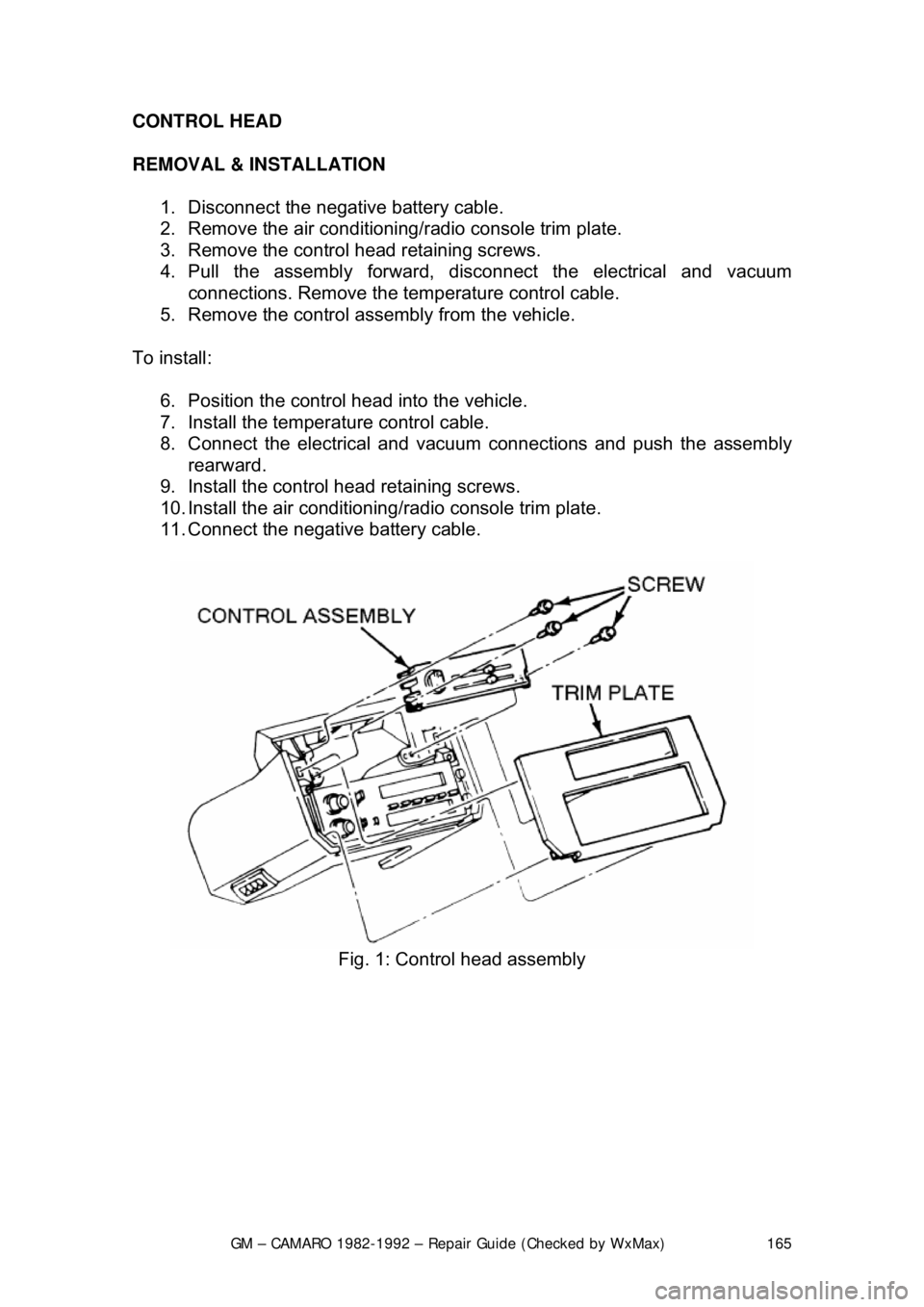
REMOVAL & INSTALLATION
1. Disconnect the negative battery cable.
2. Remove the air conditioning/ radio console trim plate.
3. Remove the control head retaining screws.
4. Pull the assembly forward, di sconnect the electrical and vacuum
connections. Remove the tem perature control cable.
5. Remove the control assembly from the vehicle.
To install: 6. Position the control head into the vehicle.
7. Install the temperat ure control cable.
8. Connect the electrical and vacuum connections and push the assembly rearward.
9. Install the control head retaining screws.
10. Install the air conditioning/ radio console trim plate.
11. Connect the negative battery cable.
Fig. 1: Control head assembly
Page 166 of 875
GM – CAMARO 1982-1992 – Repair Guide (Checked by WxMax) 166
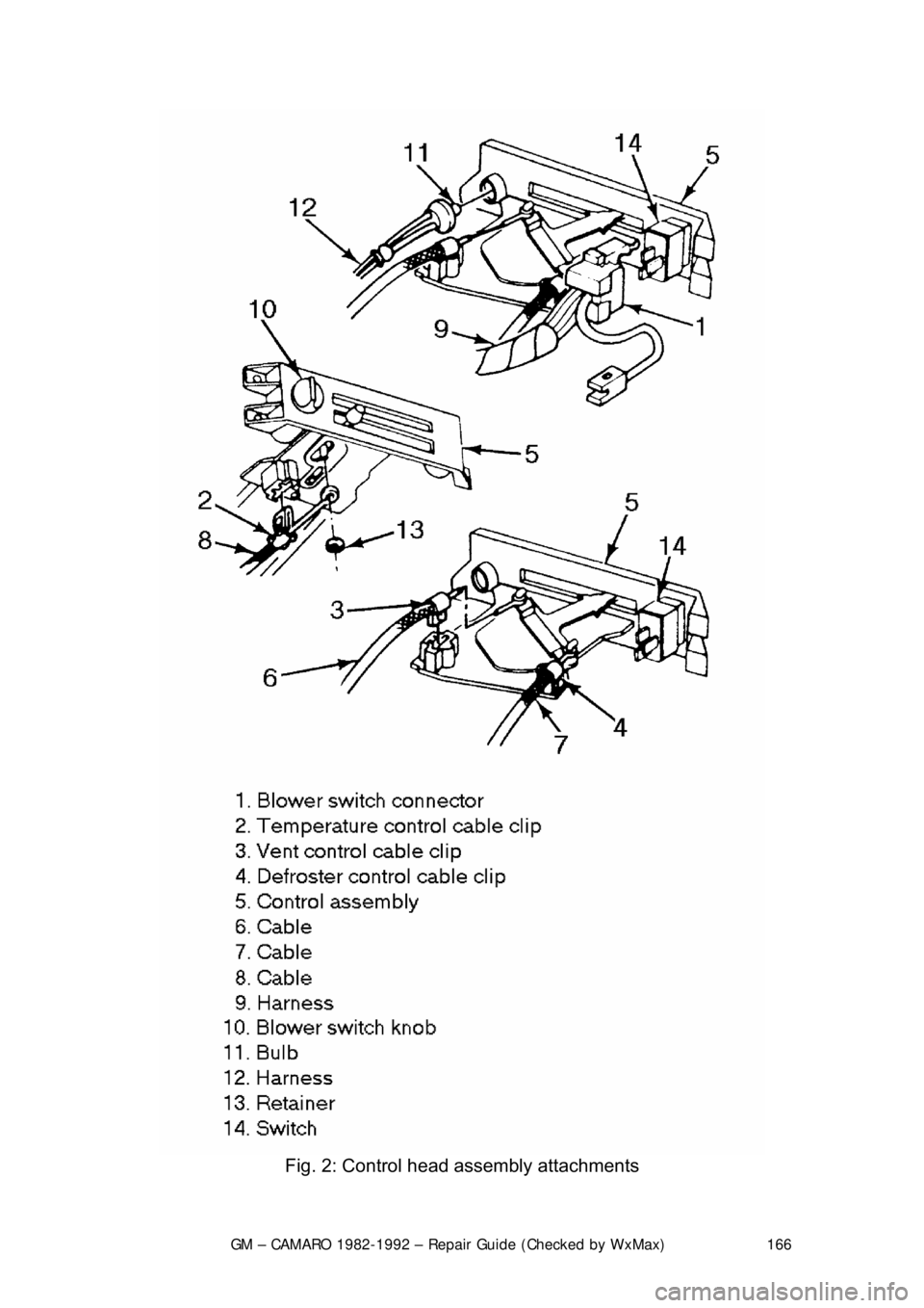
Fig. 2: Control head assembly attachments
Page 167 of 875

GM – CAMARO 1982-1992 – Repair Guide (Checked by WxMax) 167
BLOWER SWITCH
With the control head removed from t
he vehicle, the blower switch may be
removed by pulling the blower switch knob off and removing the retaining clip or
retaining screws.
VACUUM MOTORS
OPERATION
Used on certain heating and air condition ing systems, the vacuum actuators
operate the air doors determining the differ ent modes. The actuator consists of
a spring loaded diaphragm connec ted to a lever. When vacuum is applied to the
diaphragm, the lever moves t he control door to its appropriate position. When
the lever on the control panel is moved to another position, vacuum is cut off
and the spring returns the actuator lever to its normal position.
TESTING 1. Disconnect the vacuum line from the actuator.
2. Attach a hand held vacuum pump to the actuator.
3. Apply vacuum to the actuator.
4. The actuator lever should move to its engaged position and remain there
while vacuum is applied.
5. When vacuum is released it should move back to its normal position.
6. The lever should operat e smoothly and not bind.
REMOVAL & INSTALLATION 1. Remove the vacuum li nes from the actuator.
2. Disconnect the linkage from the actuator.
3. Remove the hardware attaching the actuator.
4. Remove the actuator.
To install: 5. Install the actuator and attaching hardware.
6. Connect the linkage to the actuator.
7. Connect the vacuum lines to the actuator.
8. Test system to confirm proper functioning of the actuator.
Page 168 of 875
GM – CAMARO 1982-1992 – Repair Guide (Checked by WxMax) 168
CRUISE CONTROL
CONTROL SWITCHES
REMOVAL & INSTALLATION
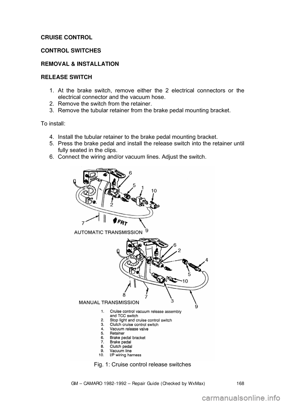
RELEASE
SWITCH
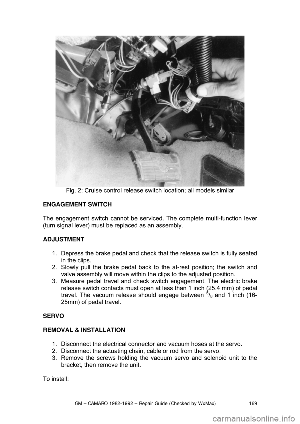
1. At the brake switch, remove either the 2 electrical connectors or the
electrical connector and the vacuum hose.
2. Remove the switch from the retainer.
3. Remove the tubular retainer fr om the brake pedal mounting bracket.
To install: 4. Install the tubular retainer to the brake pedal mounting bracket.
5. Press the brake pedal and install the release switch into the retainer until
fully seated in the clips.
6. Connect the wiring and/or vac uum lines. Adjust the switch.
Fig. 1: Cruise control release switches
Page 169 of 875
GM – CAMARO 1982-1992 – Repair Guide (Checked by WxMax) 169
Fig. 2: Cruise control release sw itch location; all models similar
ENGAGEMENT SWITCH
The engagement switch cannot be serviced . The complete multi-function lever
(turn signal lever) must be replaced as an assembly.
ADJUSTMENT
1. Depress the brake pedal and check that the release switch is fully seated
in the clips.
2. Slowly pull the brake pedal back to the at-rest position; the switch and
valve assembly will move within the clips to the adjusted position.
3. Measure pedal travel and check s witch engagement. The electric brake
release switch contacts must open at less than 1 inch (25.4 mm) of pedal
travel. The vacuum release should engage between
5/8 and 1 inch (16-
25mm) of pedal travel.
SERVO
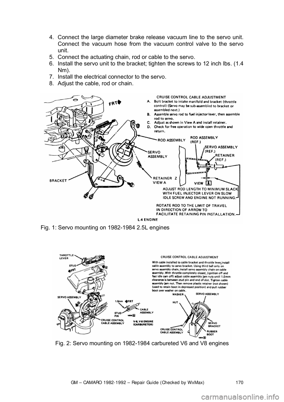
REMOVAL & INSTALLATION 1. Disconnect the electrical connecto r and vacuum hoses at the servo.
2. Disconnect the actuating chain, cable or rod from the servo.
3. Remove the screws holding the vac uum servo and solenoid unit to the
bracket, then remove the unit.
To install:
Page 170 of 875
GM – CAMARO 1982-1992 – Repair Guide (Checked by WxMax) 170
4. Connect the large diamet
er brake release vacuum line to the servo unit.
Connect the vacuum hose from the va cuum control valve to the servo
unit.
5. Connect the actuating chain, rod or cable to the servo.
6. Install the servo unit to the bracket; tighten the screws to 12 inch lbs. (1.4
Nm).
7. Install the electrical connector to the servo.
8. Adjust the cable, rod or chain.
Fig. 1: Servo mounting on 1982-1984 2.5L engines
Fig. 2: Servo mounting on 1982-1984 carbureted V6 and V8 engines