air condition CHEVROLET CAMARO 1982 Repair Guide
[x] Cancel search | Manufacturer: CHEVROLET, Model Year: 1982, Model line: CAMARO, Model: CHEVROLET CAMARO 1982Pages: 875, PDF Size: 88.64 MB
Page 160 of 875

GM – CAMARO 1982-1992 – Repair Guide (Checked by WxMax) 160
damage, and legal considerations (such as t
he fact that it is a federal crime to
vent refrigerant into the atmosphere), dictate that the A/C components on your
vehicle should be serviced only by a Motor Vehicle Air Conditioning (MVAC)
trained, and EPA certified aut omotive technician.
If your vehicle's A/C system uses R-12 re frigerant and is in need of recharging,
the A/C system can be c onverted over to R-134a refrigerant (less
environmentally harmful and expensive). Refer to General Information &
Maintenance for additional information on R- 12 to R-134a conversions, and for
additional considerations dealing with your vehicle's A/C system.
CONTROL CABLES
REMOVAL & INSTALLATION
Some of the following cables will not be used on all models and model years.
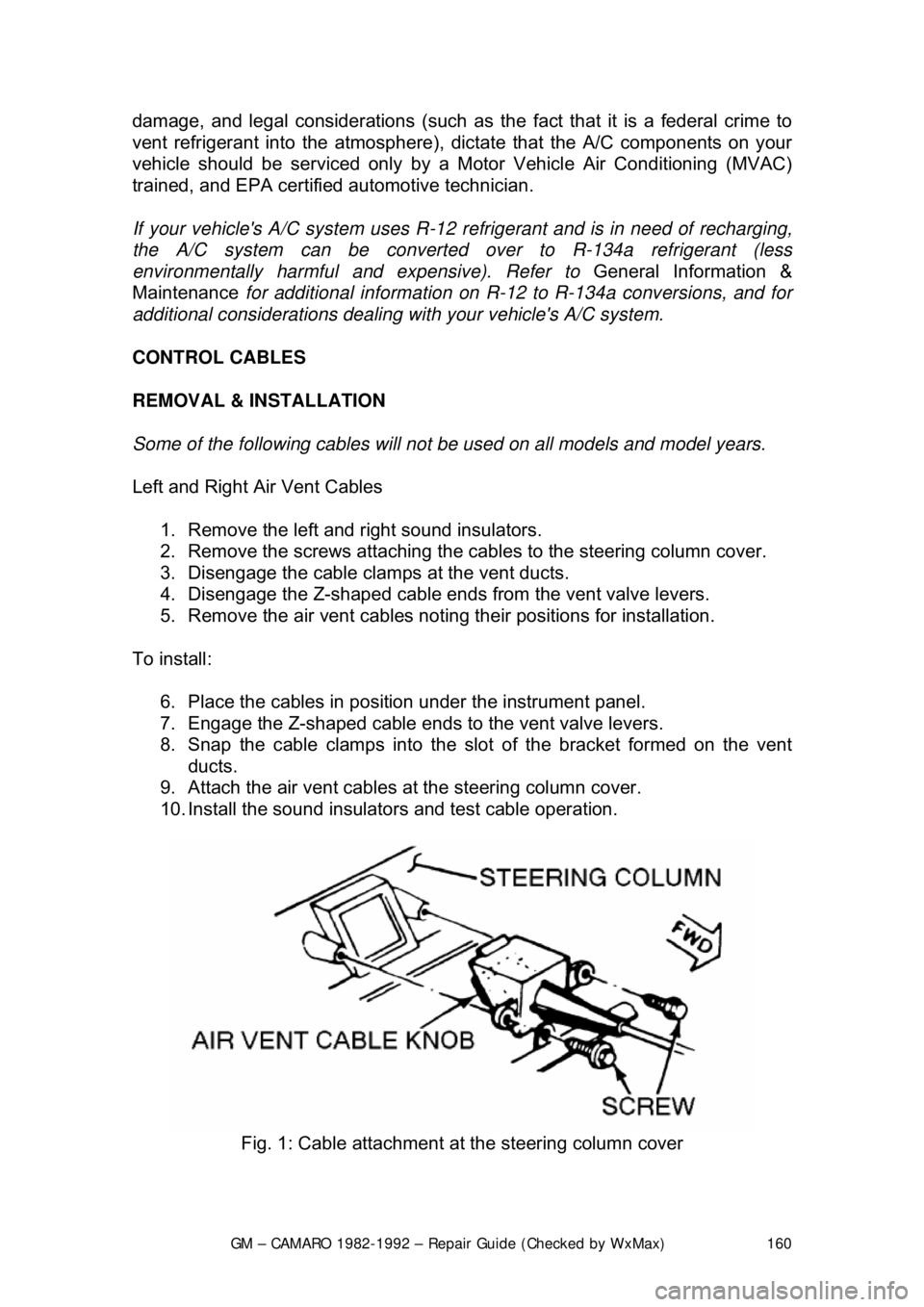
Left and Right Air Vent Cables 1. Remove the left and right sound insulators.
2. Remove the screws attaching the cabl es to the steering column cover.
3. Disengage the cable clamps at the vent ducts.
4. Disengage the Z-shaped c able ends from the vent valve levers.
5. Remove the air vent cables notin g their positions for installation.
To install: 6. Place the cables in posi tion under the instrument panel.
7. Engage the Z-shaped cable ends to the vent valve levers.
8. Snap the cable clamps into the slot of the bracket formed on the vent
ducts.
9. Attach the air vent cables at the steering column cover.
10. Install the sound insulators and test cable operation.
Fig. 1: Cable attachment at the steering column cover
Page 165 of 875

GM – CAMARO 1982-1992 – Repair Guide (Checked by WxMax) 165
CONTROL HEAD
REMOVAL & INSTALLATION
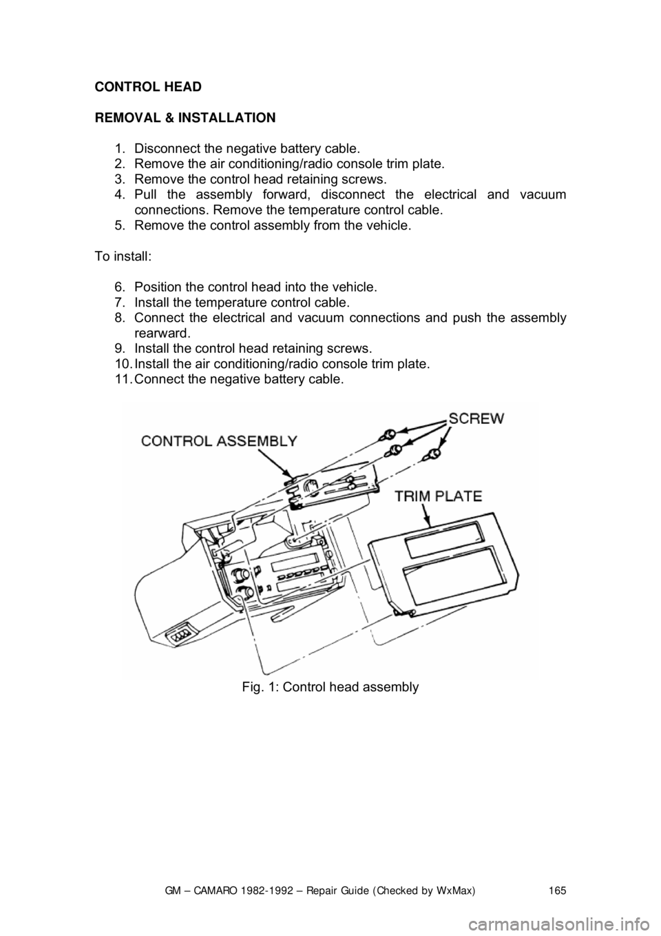
1. Disconnect the negative battery cable.
2. Remove the air conditioning/ radio console trim plate.
3. Remove the control head retaining screws.
4. Pull the assembly forward, di sconnect the electrical and vacuum
connections. Remove the tem perature control cable.
5. Remove the control assembly from the vehicle.
To install: 6. Position the control head into the vehicle.
7. Install the temperat ure control cable.
8. Connect the electrical and vacuum connections and push the assembly rearward.
9. Install the control head retaining screws.
10. Install the air conditioning/ radio console trim plate.
11. Connect the negative battery cable.
Fig. 1: Control head assembly
Page 167 of 875

GM – CAMARO 1982-1992 – Repair Guide (Checked by WxMax) 167
BLOWER SWITCH
With the control head removed from t
he vehicle, the blower switch may be
removed by pulling the blower switch knob off and removing the retaining clip or
retaining screws.
VACUUM MOTORS
OPERATION
Used on certain heating and air condition ing systems, the vacuum actuators
operate the air doors determining the differ ent modes. The actuator consists of
a spring loaded diaphragm connec ted to a lever. When vacuum is applied to the
diaphragm, the lever moves t he control door to its appropriate position. When
the lever on the control panel is moved to another position, vacuum is cut off
and the spring returns the actuator lever to its normal position.
TESTING 1. Disconnect the vacuum line from the actuator.
2. Attach a hand held vacuum pump to the actuator.
3. Apply vacuum to the actuator.
4. The actuator lever should move to its engaged position and remain there
while vacuum is applied.
5. When vacuum is released it should move back to its normal position.
6. The lever should operat e smoothly and not bind.
REMOVAL & INSTALLATION 1. Remove the vacuum li nes from the actuator.
2. Disconnect the linkage from the actuator.
3. Remove the hardware attaching the actuator.
4. Remove the actuator.
To install: 5. Install the actuator and attaching hardware.
6. Connect the linkage to the actuator.
7. Connect the vacuum lines to the actuator.
8. Test system to confirm proper functioning of the actuator.
Page 200 of 875

GM – CAMARO 1982-1992 – Repair Guide (Checked by WxMax) 200
9. Lubricate the speedometer cable
with an appropriate lubricant, being
sure to cover the lower thirds of the cable.
10. Insert the cable into the casi ng, then connect the cable and casing
assembly to the speedometer.
11. Install the instrument cluster, then install the cluster attaching screws.
12. Install the instrument cluster trim plate.
13. On models without cruise control, connect the speedometer cable strap
at the power brake booste r. On models with cruise control, connect the
speedometer cable at the cr uise control transducer.
14. Connect the negative battery cable at the battery.
WIPER SWITCH
REMOVAL & INSTALLATION
The wiper switch is part of the multi-function lever, located on the steering
wheel column.
1. Disconnect the electrical connector of the multi-function lever, located
under the instrument panel.
2. Remove the protective cover from the wire.
3. Grasp the lever firmly, twist and pull (the tang on the lever must align
with the socket) the lever straight out.
4. Pull the wire through the steering column.
To install: 5. Slide a music wire tool through the steering column and connect the
lever wire to the tool wire; pull t he wire through the steering column.
6. Push the control lever into the sp ring loaded socket (be sure to align the
tang).
7. Install the protective cover to the wire.
8. Connect the electrical connector of the multi-function lever.
HEADLIGHT SWITCH
REMOVAL & INSTALLATION 1. Disconnect the negative batte ry cable at the battery.
2. Remove the four screws from insi de the defroster duct (instrument panel
pad securing screws).
3. Remove the screws which are under the lip of the instrument panel pad.
4. Remove the instrument panel pad.
5. On models equipped with air condition ing, remove the instrument panel
cluster bezel and the cluster.
6. Remove the radio speaker bracket.
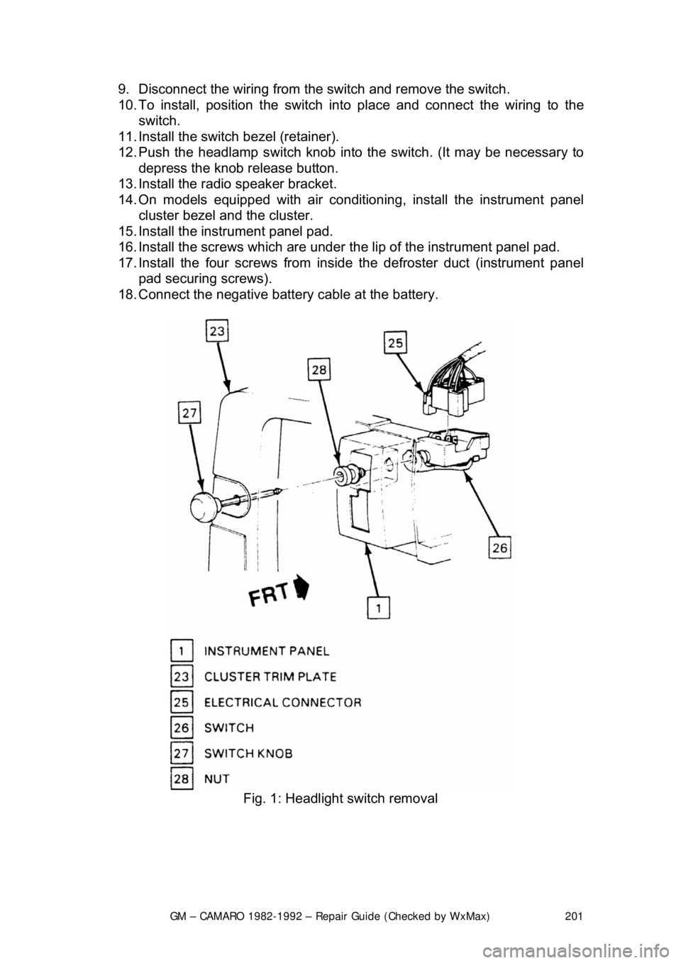
7. Pull the headlamp switch knob to the ON position, depress the locking
button for the knob and shaft (locat ed on the switch), and remove the
knob and shaft.
8. Remove the switch bezel (retainer).
Page 201 of 875

GM – CAMARO 1982-1992 – Repair Guide (Checked by WxMax) 201
9. Disconnect the wiring from the
switch and remove the switch.
10. To install, position t he switch into place and connect the wiring to the
switch.
11. Install the switch bezel (retainer).
12. Push the headlamp switch knob into the switch. (It may be necessary to
depress the knob release button.
13. Install the radio speaker bracket.
14. On models equipped with air conditioni ng, install the instrument panel
cluster bezel and the cluster.
15. Install the inst rument panel pad.
16. Install the screws which are under t he lip of the instrument panel pad.
17. Install the four screw s from inside the defroster duct (instrument panel
pad securing screws).
18. Connect the negative battery cable at the battery.
Fig. 1: Headlight switch removal
Page 302 of 875

GM – CAMARO 1982-1992 – Repair Guide (Checked by WxMax) 302
7. To install, reverse the removal
procedures. Torque the master cylinder-
to-cowl brace nuts to 10-15 ft. lbs. (14-20 Nm). Fill master cylinder with
new hydraulic fluid conforming to DO T 3 specifications. Bleed and check
the hydraulic clutch system for leaks.
OVERHAUL 1. Remove the filler cap and drain fl uid from the master cylinder.
2. Remove the reservoir and seal from the master cylinder. Pull back the
dust cover and remove the snapring.
3. Remove the push rod assembly. Usi ng a block of wood, tap the master
cylinder on it to eject the plunger a ssembly from the cylinder bore.
4. Remove the seal (carefully) from the front of the plunger assembly,
ensuring no damage occurs to the plunger surfaces.
5. From the rear of t he plunger assembly, remove the spring, the support,
the seal and the shim.
6. Using clean brake fluid, clean all of the parts.
7. Inspect the cylinder bore and t he plunger for ridges, pitting and/or
scratches, the dust cover for wear and cracking; replace the parts if any
of the conditions exist.
To assemble: 8. Use new seals, lubric ate all of the parts in clean brake fluid, fit the
plunger seal to the plunger and reve rse the disassembly procedures.
9. Insert the plunger assembly, va lve end leading into the cylinder bore
(easing the entrance of the plunger seal).
10. Position the push rod assembly into the cylinder bore, then install a new
snapring to retain the push rod. Install dust cover onto the master
cylinder. Lubricate the inside of t he dust cover with Girling® Rubber
Grease or equivalent.
Be careful not to use any lubricant that will deteriorate rubber dust covers or
seals.
SLAVE CYLINDER
On vehicles equipped with a hydraulic clutch release mechanism, the slave
cylinder is located on the left side of the bellhousing and controls the clutch
release fork operation.
REMOVAL & INSTALLATION
1. Disconnect the negative battery cable.
2. Raise and safely support the front of the vehicle on jackstands.
3. Disconnect the hydraulic line from clutch master cylinder. Remove the
line-to-chassis screw and the c lip from the chassis.
Be sure to plug the line opening to k eep dirt and moisture out of the system.
Page 303 of 875

GM – CAMARO 1982-1992 – Repair Guide (Checked by WxMax) 303
4. Remove the slave cyli
nder-to-bellhousing nuts.
5. Remove the push rod and the slav e cylinder from the vehicle, then
overhaul it (if necessary).
6. To install, reverse the removal pr ocedures. Lubricate leading end of the
slave cylinder with Girli ng® Rubber Lube or equiva lent. Torque the slave
cylinder-to-bellhousing nuts to 10-15 ft. lbs. (14-20 Nm). Fill the master
cylinder with new brake fluid conformi ng to DOT 3 specifications. Bleed
the hydraulic system.
OVERHAUL 1. Remove the shield, the pushrod and the dust cover from the slave cylinder, then inspect the cover for damage or deterioration.
2. Remove the snapring form t he end of the cylinder bore.
3. Using a block of wood, tap the slave cylinder on it to eject the plunger,
then remove the seal and the spring.
4. Using clean brake fluid, clean all of the parts.
5. Inspect the cylinder bore and the plunger for ridges, pitting and/or
scratches, the dust cover for wear and cracking; replace the parts if any
of the conditions exist.
To assemble: 6. Use new seals and lubricat e all of the parts in clean brake fluid. Install
the spring, the plunger seal and the plunger into the cylinder bore, then
install anew snapring.
7. Lubricate the inside of the dust co ver with Girling® Rubber Grease or
equivalent, then install it into the slave cylinder.
Be careful not to use any lubricant that will deteriorate rubber dust covers or
seals.
BLEEDING THE HYDRAULIC CLUTCH
Bleeding air from the hydrau lic clutch system is necessary whenever any part of
the system has been disconnect ed or the fluid level (in the reservoir) has been
allowed to fall so low that air has been drawn into the master cylinder.
1. Fill master cylinder reservoir wit h new brake fluid conforming to DOT 3
specifications.
2. Raise and safely support the front of the vehicle on jackstands.
3. Remove the slave cylinder attaching bolts.
4. Hold slave cylinder at approximatel y 45 degrees with the bleeder at
highest point. Fully depress clutch pedal and open the bleeder screw.
5. Close the bleeder screw and release clutch pedal.
6. Repeat the procedure until all of t he air is evacuated from the system.
Check and refill master cylinder reserv oir as required to prevent air from
being drawn through the master cylinder.
Page 306 of 875

GM – CAMARO 1982-1992 – Repair Guide (Checked by WxMax) 306
As the speed of the turbine increases, th
e fluid spins faster and faster in the
direction of engine rotation. As a result, t he ability of the stator to redirect the
fluid flow is reduced. Under cruising conditions, the stator is eventually forced to
rotate on its one-way clutch in the dire ction of engine rotation. Under these
conditions, the torque converter begins to behave almost like a solid shaft, with
the torus and turbine speeds being almost equal.
PLANETARY GEARBOX
The ability of the torque converter to mult iply engine torque is limited. Also, the
unit tends to be more efficient when the turbine is rotating at relatively high
speeds. Therefore, a planetar y gearbox is used to carry the power output of the
turbine to the driveshaft.
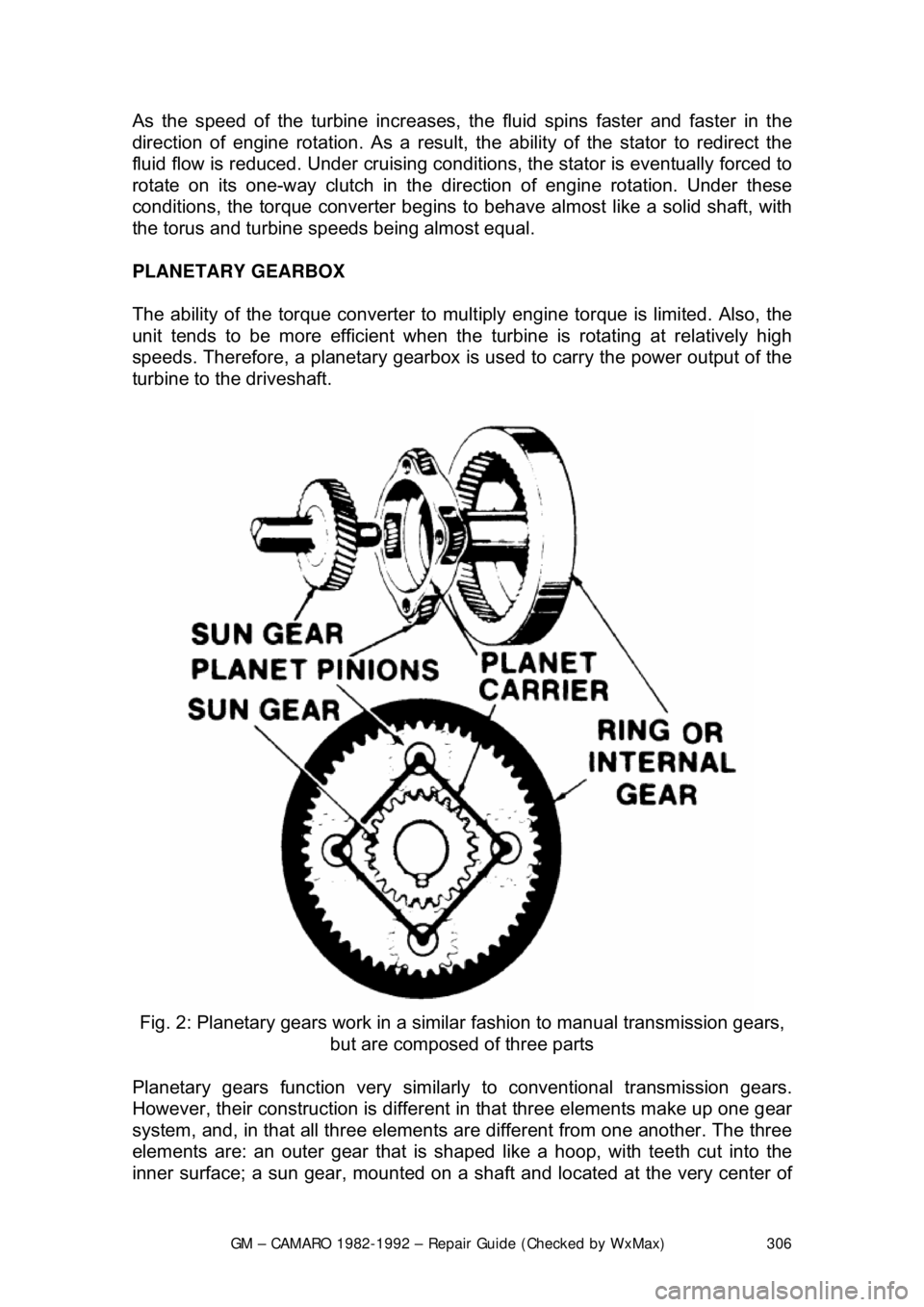
Fig. 2: Planetary gears work in a sim ilar fashion to manual transmission gears,
but are composed of three parts
Planetary gears function very similarly to conventional transmission gears.
However, their construction is different in that three elements make up one gear
system, and, in that all three elements ar e different from one another. The three
elements are: an outer gear that is shaped like a hoop, with teeth cut into the
inner surface; a sun gear, mounted on a sha ft and located at the very center of
Page 344 of 875

GM – CAMARO 1982-1992 – Repair Guide (Checked by WxMax) 344
ENGINE & ENGINE OVERHAUL
ENGINE ELECTRICAL
ENGINE ELECTRICAL
The engine electrical system can be brok en down into three inter-related, but
distinct systems:
1. The starting system.
2. The charging system.
3. The ignition system.
BATTERY AND STARTING SYSTEM
The battery is the first link in the chai n of mechanisms which work together to
provide cranking of the autom obile engine. In most modern cars, the battery is a
lead-acid electrochemical device consis ting of six two-volt (2V) subsections
connected in series so the unit is c apable of producing approximately 12V of
electrical pressure. Each subsection, or ce ll, consists of a series of positive and
negative plates held a short distance apart in a solution of sulfuric acid and
water. The two types of plates are of di ssimilar metals. This causes a chemical
reaction to be set up, and it is this reacti on which produces current flow from the
battery when its positive and negative te rminals are connected to an electrical
appliance such as a lamp or motor.
The continued transfer of electrons would ev entually convert the sulfuric acid in
the electrolyte to water and make t he two plates identical in chemical
composition. As electrical energy is removed from the battery, its voltage output
tends to drop. Thus, measuring batte ry voltage and battery electrolyte
composition are two ways of checking the ability of the unit to supply power.
During the starting of the eng ine, electrical energy is removed from the battery.
However, if the charging circuit is in good condition and the operating conditions
are normal, the power removed from the battery will be replaced by the
generator (or alternator) which will forc e electrons back through the battery,
reversing the normal flow, and restoring the ba ttery to its original chemical state.
The battery and starting motor are linked by very heavy electrical cable\
s
designed to minimize resistance to the flow of current. Generally, the major
power supply cable that leaves the batte ry goes directly to the starter, while
other electrical system needs are supplied by a smaller cable. During the starter
operation, power flows from the battery to the starter and is grounded through
the car's frame and the batte ry's negative ground strap.
The starting motor is a specially designed, direct current electric motor capable
of producing a very great am ount of power for its size. One thing that allows the
motor to produce a great deal of power is its tremendous rotating speed. It
drives the engine through a ti ny pinion gear (attached to the starter's armature),
which drives the very large flywheel ring gear at a greatly reduced speed.
Another factor allowing it to produce so much power is that only intermittent
Page 352 of 875

GM – CAMARO 1982-1992 – Repair Guide (Checked by WxMax) 352
To prevent serious damage to the alte
rnator and the rest of the charging
system, the following precauti ons must be observed:
• Never reverse the battery connections.
• Booster batteries for starting must be connected properly: positive-to-
positive and negative-to-ground.
• Disconnect the battery cables before using a fast charger; the charger
has a tendency to force current through the diodes in the opposite
direction for which they were designed. This burns out the diodes.
• Never use a fast charger as a booster for starting the vehicle.
• Never disconnect the voltage regulator while the engine is running.
• Avoid long soldering times when replacing diodes or transistors.
Prolonged heat is damaging to AC alternators.
• Do not use test lamps of more t han 12 volts (V) for checking diode
continuity.
• Do not short across or ground any of the terminals on the AC alternator.
• The polarity of the battery, alter nator, and regulator must be matched
and considered before making any elec trical connections within the
system.
• Never operate the alternator on an open circuit. make sure that all
connections within the circ uit are clean and tight.
• Disconnect the battery terminals when performing any service on the
electrical system. This wil l eliminate the possibility of accidental reversal
of polarity.
• Disconnect the battery ground cable if arc welding is to be done on any
part of the car.
CHARGING SYSTEM TROUBLESHOOTING
There are many possible ways in whic h the charging system can malfunction.
Often the source of a problem is diffi cult to diagnose, requiring special
equipment and a good deal of experience. However, when the charging system
fails completely and causes the dash boar d warning light to come on or the
battery to become dead the following items may be checked:
1. The battery is known to be good and fully charged.
2. The alternator belt is in good condition and adjusted to the proper
tension.
3. All connections in t he system are clean and tight.
REMOVAL & INSTALLATION